
9
Thin Plate Bending
Beam bending tests are inappropriate for the experimental study of materials in the thin form, such as metal thin sheets. Indeed, if samples of thickness ranging from 0.1 to 0.3 mm, instead of ranging from 1.5 to 2 mm, are considered, a free bending test generates a transverse bending in addition to the longitudinal bending. The vibration mode then becomes a mixed plate-beam state. An experimental study of such geometries requires thin plate bending tests, which will be considered square in order to simplify the process. This chapter focuses on this new configuration.
9.1. Bending vibrations of a homogeneous thin plate
Consider a homogeneous plate of length L along the x and y directions, of thickness B along the z direction, and Young’s modulus E, Poisson’s ratio ν, density ρ and having a bending resonance frequency FFP. According to the Euler–Bernoulli kinematic hypothesis (shears γxz and γyz are zero), three deformations generated can be written as follows:
It can be seen that the double deflection in the x and y directions generates a shear. The deformation energy can be written as:
According to Hooke’s law, the relations between stresses and deformations are:
Inserting [9.5] into [9.4], the new expression of the deformation energy is given by:

The displacement energy can be written as:
The integration with respect to z yields the expression of the Lagrangian:
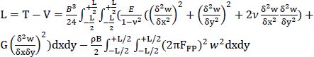
The minimization of the Lagrangian yields:

Assuming that the material is isotropic, the last expression becomes:

The integration by parts is complex in this case, as both double integrations and a mixed double integration must be performed with respect to x and y. This is why the description of the boundary conditions is complex; as the focus in what follows is on various experimental conditions, this problem will be discussed in the next chapter.
Nevertheless, the vibration equation is simple to describe and the double integrations yield:
Here Δ is the Laplace operator, and if this equation is compared to [7.11] for the simple bending of the beam, the double deflection effect is clear. In order to solve this homogeneous differential equation, abundant parameterization is required. Indeed, any pair of eigenvalues (λ’,λ’’) and any function of Sh(λ’x/L)Sh(λ’’y/L), sin(λ’x/L)sin(λ’’y/L), Ch(λ’x/L)Ch(λ’’y/L), cos(λ’x/L)cos(λ’’y/L) type, as well as those permutating sine and cosine or Sh and Ch, are the solution to the equation as soon as it verifies:
It is possible to find in the literature (Warburton 1954) approximate solutions for certain support or clamping conditions. The next section describes only two simple cases that may have potential experimental applications.
9.2. Application to the characterization of thin plate elasticity
The only simple degenerate solution is the case of the (square) plate supported on all these edges. In this case, this solution is:
where k and l are integers equal to or greater than 1; it verifies the displacement and torque boundary conditions which are zero at any point of the edge:
The fundamental vibration has the following form:
Since this solution is simple, a substrate adapted to this configuration, namely a substrate cut by a square whose dimensions are slightly below those of the plate, is machined to test the method.
This configuration is unfortunately unstable. If the electrode at the center of the plate is excited, the plate reaches a state of resonance, which is unstable. Due to the low inertia of the sample, the resonance peak tends to deform and has a frequency shift, with transverse vibrations appearing due to low displacements on the support points.
Since this solution is not viable, an effective alternative must be found. For this purpose, the fourth vibration harmonics verifying k=l=2 must be examined:
For this harmonic, the plate is represented by four equal quadrants undergoing two-by-two in-phase vibration; however, all their displacements are zero on the edges. Considering now the torsion setup with cross wires (Figure 5.1), let us place the plate at the center (symmetric position of the support wires); this system and configuration are compatible if the excitation electrode is placed at the center of one of the quadrants. However, as the edges are free, the boundary conditions are no longer the same and the solution to the vibration equation is no longer degenerate.
This new vibration equation must be found from zero displacements in x=y=0, the symmetry of the configuration, the similarity with the free bending of the beam and the conditions at free edges. All these considerations lead us to propose a solution of the type:
Resuming the boundary conditions resulting from the first integration by parts of equation [9,11], the following expression can be obtained for x=±L/2/:
This expression can be written along the entire contour:
This is an indeterminacy, as in the case of a zero product. If the same approach is applied for y=±L/2, the result is exactly the same. This indeterminacy can be lifted using another condition related to the symmetry of the sought-for solution, that is, the displacement integrated over the whole plate must be zero (stationary solution). Resuming equation [9.16], a double integration with respect to x and y yields:
Considering now equation [9.18] applicable to the contour (x=y=±L/2), it is the second term of the product, namely δ2w/δxδy, that yields exactly the same relation. For the second boundary condition, there is no ambiguity, and a second integration yields:
The elimination of C yields equation [7.16] and therefore the eigenvalue λ=4.73 verifies:
Finally, the relation between Young’s modulus and the resonance frequency is:
With respect to the beam bending (equation [5.1]), a factor of 4 appears due to the double deflection and the presence of Poisson’s ratio is explained by the biaxial deformation.
In order to obtain this particular vibration mode, the electrode should be placed in an ideal location; a rapid calculation giving the place for which there is maximal displacement indicates that the ideal positioning is at 0.6 of the diagonal of one of the quadrants (for the supported mode it was at 0.5). This type of vibration is illustrated in Figure 9.1 on a quadrant. First tests have shown that this mode could be effectively “activated”, presenting no instability problem.
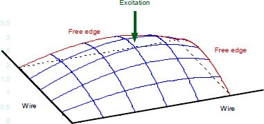
Figure 9.1. Vibration mode on a quarter of the plate. For a color version of this figure, see www.iste.co.uk/gadaud/elasticity.zip
This calculation was made within the project for the characterization of the elasticity of thin sheets of various metals; as the project was not successful, no systematic experimental study was conducted to apply this method.
Anyway, there are two ways of reasoning on the principle of its application. The first one is to consider that E is previously known or measured during beam bending and that Poisson’s ratio can thus be deduced. But since in the first case the working material is generally a foundry material and in the second case it is a highly rolled material, a relatively significant difference in Young’s modulus may arise. The second working hypothesis is to assimilate Poisson’s ratio of the rolled material to that of the foundry material (the presence of a texture should not induce a very high variation of this parameter); in this case, moduli in foundry and rolled states can be compared.