7
Hybrid Approach based on Multi-agent System and Fuzzy Logic for Mobile Robot Autonomous Navigation
Khadidja YAHYAOUI
University of Mascara, Algeria
The design of a control architecture is a central problem in a project to realize an autonomous mobile robot. In the absence of a generic solution that overshadows all others, it is essential to come up with a new approach detailing the design process that will reach this goal. In this context, this chapter proposes to use the multi-agent paradigm and inference mechanism based on fuzzy logic in the design of the control architecture for the autonomous navigation of the mobile robot.
The architecture developed must take into account imposed constraints (obstacle avoidance, no collisions with the walls of the environment, unknown environment, optimal path, reaching the goal), actor-based system multi-agents and distributed non-hierarchical architecture built around several agents (databases knowledge), cognitive and reactive, that cooperate with each other to solve the problem of autonomous navigation of the mobile robot.
The method used allowed us to have an intelligent system capable of solving various problems produced during navigation.
7.1. Introduction
The industry mainly uses poorly autonomous robots to perform repetitive tasks with the aim of reducing production costs. Robots can be used in tasks that are dangerous for humans, such as those carried out in underground mines, chemical or nuclear installations, the underwater world and planetary exploration. Thus, environments hostile to humans are at the origin of the growing interest in the development of robots capable of assisting humans and tending to an increasingly strong autonomy.
Navigating the robot to approach the target while avoiding any obstacle in a constrained environment, is one of the most complex problems, and the majority of robotics specialists have directed their research toward this axis.
This chapter presents two artificial intelligence tools: multi-agent systems (MAS) and fuzzy logic to design and implement the control architecture for autonomous navigation of a mobile robot, taking into account the changing nature of the environment.
We opted for a hybridization between MAS and fuzzy logic for several reasons:
- – The principle of adjustment and control by fuzzy logic approaches the human approach in the sense that the variables processed are not logical variables (in the sense of binary logic, for example), but linguistic variables, close to human language. In addition, these linguistic variables are treated using rules which refer to knowledge about the behavior of the system to be controlled (Buhler 1994).
- – MAS are ideally designed and implemented as a set of interacting agents, most often in modes of cooperation, competition or coexistence (Chaib-draa 1994; Ferber 1995; Moulin and Chaib-draa 1996; Chaib-draa et al. 2001). The control architecture of a mobile robot is an organization allowing the construction of a complex system from elementary bricks, which are the multiple modules that are each attached to the resolution of a sub-problem (Ahmadzadeh and Masehian 2015). In this context, the development of this control architecture based MAS allows the coordination of perception, decision and action functions.
- – The remainder of the chapter is organized as follows: section 7.2 provides the key methods used for mobile robot navigation as related works. Section 7.3 introduces the problem position. In section 7.4, we describe the control architecture based agent. The adopted method is explained in section 7.5. Section 7.6 provides a discussion on the methods for evaluating an agent system, and finally, section 7.7 concludes the chapter.
7.2. Related works
Mobile and autonomous robotics is one of the research areas for which the arrival of a new approach in artificial intelligence (AI) will have had an interesting impact. The transition from a classical approach (mathematical and algorithmic) to a behavioral approach (based on notions such as cognition, learning, emergence and corporeality) is not easy, because it involves radical changes of mentality and major changes in the designing of robotic control architectures. The main challenge for these architectures is to generate so-called “intelligent” behaviors when subjected to complex and dynamic environments, such as autonomy, learning, adaptation, deliberation, intentions and many others (Holzmann et al. 2005). Thus, navigation methods for mobile robots have two classes: classical approaches and advanced approaches. The nature of the environment determines the approach to navigation. For a known or partially known environment, we opt for conventional approaches and, on the other hand, if the environment is unknown then the current approaches are presented in Figure 7.1. In this case, there is no way to make a trajectory planning for the robot beforehand.

Figure 7.1. Mobile robot navigation approaches
7.2.1. Classical approaches
These approaches have the environment in common, which is totally or partially known, that is to say, a static and straightforward environment. Therefore, the mobile robot can plan a continuous trajectory, free of obstacles. These methods are based on the configuration of space and so-called potential field methods.
7.2.1.1. Methods based on the configuration of space
This is one of the techniques based on the cell decomposition process, using a discrete representation of the robot’s environment. Exact decomposition gives a set of polygons dividing the space of free configurations from this representation; we create a graph connecting the various adjacent components of the environment. Next, the cells in which the initial configuration and the target configuration are located are identified. The planning problem then consists of a search problem in a graph. For this, we choose a route algorithm (A *, depth-first, breadth-first) to optimize the distance traveled, or any other criterion. Finally, the cells of the solution graph must be connected by a path without collisions. Several works have used these methods, including Lozano-Pérez (1983), Schwartz and Yap (1987) and Pan and Dinesh Manocha (2015).
7.2.1.2. Potential field methods
The potential method was initially introduced by Khatib (1986) to manipulate robots. It differs significantly from the other methods mentioned above, because it does not result from purely geometric reasoning. The principle of the method is as follows. The mobile robot is immersed in a field of potential which results from the superposition of an attractive potential, linked to the configuration to be reached, and a sum of repulsive potentials linked to obstacles. Several works have used these methods. In Matoui et al. (2017), the authors used the potential field method to plan the path of a group of robots in decentralized architecture. The fractional potential fields approach was applied for the navigation of autonomous vehicles in Moreau et al. (2017). Farhad et al. (2018) applied the electrostatic potential field approach for the navigation of mobile robots.
7.2.2. Advanced methods
The classical methods are methods used in the case where the displacement space is simple (without obstacles), but their limitations are revealed when the complexity of the environment increases. This is proven by the results obtained, for example, by the application of these conventional methods. Such methods generally suffer from the disadvantage of the presence of local minima (the robot is in a situation where it does not move when it has not reached its goal) (Reignier 1994). Several AI techniques are used for mobile robot navigation systems, such as Fuzzy logic systems, neural network (NN), multi-agent systems (MAS). The computing techniques such as the genetic algorithm (GA), Bee colony optimization (BCO) technique, simulated annealing (SA) and particle swarm optimization (PSO) are also applied. Some research works are presented in the following sections.
7.2.2.1. Navigation with fuzzy logic
Faisal et al. (2013) created a control architecture based on the Agent fuzzy controller for mobile robot autonomous navigation. Gul et al. (2019) steered the mobile robot to goal point and avoided obstacles. Benbouabdallah and Qi-dan (2013) created a fuzzy logic controller for searching target and path planning together with obstacle avoidance. Gul et al. (2019) gave a comprehensive study for robot navigation techniques. They cited several research works which applied fuzzy logic as a mobile robot navigation technique.
7.2.2.2. Artificial Neuronal Network
For many years, the Artificial Neuronal Network has been used as a tool for mobile robot navigation. Nguyen and Widrow (1989) gave an example of self-learning in neural networks. Engedy and Horváth (2009) described a dynamic artificial neural network based mobile robot motion and path planning system. The method made it possible to navigate a robot car on a flat surface among static and moving obstacles. Faisal et al. (2013) used the fuzzy logic for navigation and obstacle avoidance for a mobile robot in an unknown dynamic environment. Adv (2018) applied fuzzy logic as an efficient tool for the navigation of a mobile robot in an unknown dynamic environment. A performance comparison of fuzzy logic and neural network design for mobile robot navigation is given in Gul et al. (2019).
7.2.2.3. Metaheuristic
The Bee Algorithm was applied in Darwish and Joukhadar (2018). Qiongbing and Lixin (2016) used a new crossover mechanism for genetic algorithms with variable-length chromosomes for path optimization problems. The genetic algorithms were used by Alajlan et al. (2013). The Tabu search was applied as an approach for the autonomous navigation for a mobile robot in Chaaria et al. (2014). The particle swarm optimization (PSO) was used in Ahmad and Ghanavati (2012). Different nature-inspired techniques applied for motion planning of wheeled robots were used in Pandey (2018). In Capi et al. (2015), the authors used an evolutionary algorithm hybridized with the neural network for the mobile robot navigation.
7.2.2.4. Multi-agent systems
MAS have received tremendous attention from scholars in different disciplines, especially in mobile robotics. Using agents for robotics has been studied for over two decades, with the first article published in 1996 outlining the pros and cons of agents in robotics (Jenkin et al. 1996). The control architecture based on MAS was modelized for the autonomous navigation of a mobile robot. Iñigo-Blasco et al. (2012) presented a framework for multi-agent robotic systems development. Elfakharany et al. (2020) presented a method that combines both steps: Multi Robot Task Allocation (MRTA) and Multi Robot Path Planning (MRPP) by using a deep reinforcement learning model. A hybrid body sensor network architecture based on multi-sensor fusion (HBMF) was designed to support the most advanced smart medical services, which combine various sensor, communication, robot and data processing technologies. This study is realized in Lin et al. (2020).
7.3. Problem position
Figure 7.2 represents the global architecture of a mobile robot; it is a synthesis of robot architectures described in the literature.
The essential parts of this architecture are the perception module, the decision module and the locomotion module.
- – Perception module: the notion of perception in mobile robotics relates to the capacity of the system to collect, process and format information useful to the robot, in order to act and react in the world around it. While for handling tasks we can consider the robot environment to be relatively structured, this is no longer the case when it comes to navigating autonomously in partially known places. In addition, to extract the information useful for the accomplishment of its task, the robot must have many sensors that measure both its internal state and the environment in which it operates. The choice of sensors obviously depends on the intended application. To focus on the navigation problem, in this chapter we will discuss the sensors that are useful for this task.

Figure 7.2. Structure of robot architecture
- – Decision module: the information coming from various sensors must be interpreted as elements that are useful in making a decision on the action to be taken, the goal being to deliver the correct orders to the actuators, gripper arms or wheel motors. It is during this phase of the design of a robot that it is necessary to give it a form of intelligence, by giving it a choice on the action to be taken. This decision-making is often arbitrary at the beginning, but it helps to develop a form of learning that takes the results of previous decisions into account.
- – Locomotion module: the locomotion module then comprises the mechanical structure, motricity and the energy used in the movement of the mobile robot. Mobile robots are indeed most often referred to by their type of locomotion, whether they are wheeled, walking, submarine or aerial. So far, different research laboratories have contributed to the construction of different mobile robots depending on the type of locomotion.
However, we note an architectural evolution of hierarchical architectures toward the “intelligent”, which has been accompanied by a “tendency” toward more “autonomous” structures that locally manage their properties (organization, decision, action, information, communication, security, etc.) and use them to achieve the same purpose and goal (Lin et al. 2020).
Our problem is how to model and build a system that would have the main behavioral character, not to solve a well-posed problem, but to represent its environment in order to deploy it as best as possible, and to adapt to all changes that may occur during execution.
7.4. Developed control architecture
A robot is a complex system that must meet varied and sometimes contradictory requirements. A typical example for a mobile robot is the trade-off that must be made between the most precise execution of a pre-established plan to reach a goal and the unforeseen elements that should be taken into account, such as mobile obstacles. These arbitrations, whether in terms of the use of sensors, effectors or computing resources, are regulated by a software package called robot control architecture. This architecture therefore makes it possible to organize the relationships between the three main functions of perception, decision and action. In this context, a robot will be considered as a MAS and each of its components will be considered as an agent. The realization of the movement will then be the result of the coordination of a set of agents. Figure 7.3 shows the description of a mobile robot control architecture based agent.
An autonomous robot perceives the world through its sensors and acts on it via its effectors (perception-action loop). We want to have a relationship between sensors and motors to obtain the desired behavior. The global architecture developed is a fully distributed hybrid architecture and does not involve any supervisor. Agents can communicate with them directly through messages (mailboxes) or data (representations) available to the community of agents.

Figure 7.3. Mobile robot control architecture based agent. For a color version of this figure, see www.iste.co.uk/chelouah/optimization.zip
The system is designed around four agents (perception, locomotion, fuzzy controller and feasibility). They are classified into two groups. The first group contains the perception agent and the locomotion agent which have access and act on the environment. The other two, the fuzzy controller agent and the feasibility agent, are more cognitive and are strictly prohibited from having direct access to the environment. Each of these agents try to independently contribute to the system during navigation. The description of the agent system is given as follows:
7.4.1. Agents description
7.4.1.1. Perception agent
The perception agent creates representations of the environment from measurements provided by infrared sensors. For each intermediate situation, these representations are made available to other agents. Competences:
- – Give the current configuration of the robot.
- – Determine the position of the target relative to the robot (distance and orientation).
- – Determine the position of the obstacles relative to the robot for each new situation.
- – Calculate the distances and orientations of the walls of the environment. Figure 7.4 illustrates the calculation of these measurements.

Figure 7.4. Measurements provided by infrared sensors (information of perception agent and provided to all agents). For a color version of this figure, see www.iste.co.uk/chelouah/optimization.zip
7.4.1.2. Locomotion agent
It is also called the agent of action. It establishes control laws intended for controlling the robot. These commands are made from a representation established by the fuzzy controller agent. In addition, the locomotion agent activates the perception agent when the robot is parked to start a new navigation. This agent calculates the speed setpoints for the left and right wheel in order to reach the intermediate or final configuration.
Competences:
- – The procedure for calculating the values of the left and right speeds: S1 Sr as shown in Figure 7.5
with:
T: sampling time to be fixed.
The procedure for calculating is as follows:
If Δ S > 0 then the robot must turn right
If Δ S < 0 then the robot must turn left

Figure 7.5. Method for calculating speeds of the right and left wheels of the robot
Control plan:
- – Update its knowledge base.
- – Support for a fuzzy controller message (the intermediate configuration to be achieved).
- – Support for a deactivation or parking message in the event that the target is reached or in the event of a blocking situation.
- – Sending an activation message (to launch a new navigation) or deactivation (target reached, blocking) to the collection agent.
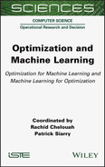
Action plan:
It is described by the sequence of the following actions, according to the following diagram presented in Figure 7.6.
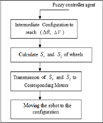
Figure 7.6. Process of locomotion agent
7.4.1.3. Feasibility agent
Its role consists of studying the feasibility of the robot’s next action to avoid the risk of collision with a possible obstacle or the walls of the environment (selection of a new behavior). The primary role of the feasibility agent reflects the aspect of MAS in optimizing the navigation function.
Competences:
- – Optimization of an objective function presented by the distance separating the intermediate configuration and the final configuration of the robot (the configuration of the target to be reached).
- – From the set of intermediate configurations, select the most suitable to have an optimal path (to quickly reach the target) and not collide with the walls of the environment.
Control:
- – Update its knowledge base (modification of the robot’s intermediate configurations).
- – Support for the message sent by the fuzzy controller agent (the list of intermediate robot configurations).
Action plan:
Figure 7.7 illustrates the feasibility agent diagram. This diagram shows the set of actions taken by the feasibility agent.

Figure 7.7. Feasibility agent general process
7.4.1.4. Fuzzy controller agent
Based on fuzzy reasoning and perception data, this agent tries to find possible openings in front of the robot to exit a given situation and continue on its way to the target. It gives the navigation information necessary for the locomotion of the robot to the locomotion agent, it also sends a deactivation order if the robot reaches the target or is in a blocking situation.
Competences:
- – Establishment of inference rules linking inputs to outputs.
- – Determine the possible outcomes in front of the robot.
- – Stop the navigation process if the target is reached or if there is a blockage situation.
- – Define the blocking situation.
Control:
- – Take charge of the feasibility agent’s message (the intermediate configuration to be reached selected).
- – Update the knowledge base (updating local representations of the environment, adding and removing openings in front of the robot, the selected intermediate state becomes the current state).
Action plan:
The agent’s action plan is presented by the following organigram:

The principle of navigation by fuzzy logic will be presented in the next section.
Communication between agents:
Communication between agents in this architecture takes place by sending and receiving asynchronous messages.
The inter agent communication is shown in Figure 7.9. It supports the transmission of messages between systems.
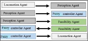
Figure 7.9. Agent interaction and communication. For a color version of this figure, see www.iste.co.uk/chelouah/optimization.zip
The messages are of following types: activation/deactivation message, request and message of results of execution of a task.
When a message is received from another agent, the decision to be made depends on the nature of the message:
- – if the message is information from another agent
 that agent is used to update the knowledge base of the receiving agent;
 - – if the message is a request it is translated into a pending goal;
- – if the message is an activation or deactivation order it will be taken into account.
7.5. Navigation principle by fuzzy logic
7.5.1. Fuzzy logic overview
Fuzzy logic is a branch of mathematics and, as such, a whole series of fundamental concepts are developed in it. These concepts make it possible to justify and demonstrate certain basic principles. In the following, we will only retain the elements essential for understanding the principle of control by fuzzy logic. These are:
- – fuzzy variables;
- – inference rules.
In general, a fuzzy logic control system consists of three important modules: fuzzyfication module, which allows the passage from the digital domain to the symbolic domain; inference module, which establishes the rules linking the inputs to the outputs, and the defuzzyfication module, which makes the transformation fuzzy information in precise physical values (Pelletier 2000).
7.5.2. Description of simulated robot
The platform chosen for our mobile robot is the differential configuration comprising:
- – two drive wheels controlled independently;
- – two idler balancing wheels, which are added to the front of the robot to ensure its stability;
- – three infrared sensors. One of these sensors is frontal and the other two are lateral to ensure the perception system of the mobile robot. This platform is very simple to control, since it suffices to specify the speeds of the two wheels, and in addition allows the robot to turn on the spot. This architecture is fairly standard and offers multiple areas of application.

The robot configuration can be described by its position at a given time presented by the following kinematic equations:


7.5.3. Strategy of navigation
The reflex action of the robot is deduced from the data analysis according to the three sides of the robot (dL, dF, dR: distances from obstacles) and the polar coordinates of the point of arrival in the robot’s coordinate system (the orientation of the target noted γ, and the distance from the target noted d), as shown in Figure 7.11.

Figure 7.11. Robot and obstacles information
7.5.4. Fuzzy controller agent
Figure 7.12 shows the interaction and communication between the fuzzy logic agent and the others agents of the MAS.
Figure 7.12. Fuzzy controller agent interaction with navigation system agent
– Input Fuzzyfication
The distances dL, DF, dR and d are evaluated with respect to the two fuzzy subsets N and F, which correspond respectively to Near and Far, as shown in Figure 7.13.

Figure 7.13. Representation of fuzzy subsets of the distance
The orientation angle of the target relative to the robot γ is represented by five fuzzy intervals: ML (left large), LL (left small), Z (zero), LR (right small) and MR (right large) covering the frontal half space of the robot, as shown in Figure 7.14.
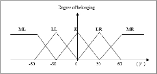
Figure 7.14. Representation of fuzzy subsets of the γ
– Output Fuzzyfication
These are the output variables Δθ and Δv.
- – The robot’s orientation angle Δθ (output variable) is represented by the five fuzzy subsets: θ LM (theta left most), θ LL (theta left little), θ Z (theta zero), θ RL (theta right little), θRM (theta right most). Figures 7.15 describes these fuzzy subsets.
- – Speed variation Δv is described by three subsets: Decspe (decrease speed), Zspe (no speed change) and Insp (increase speed). The description of these subsets is shown in Figure 7.16.
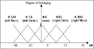
Figure 7.15. Representation of output fuzzy subsets Δθ

Figure 7.16. Representation of output fuzzy subsets Δv
- – Inference mechanism
Navigation toward a goal can be broken down into a set of elementary behaviors (set of rules), each possessing a particular skill. For each obstacle avoidance situation, the robot has one or more choices to make and it is the role of the feasibility agent to select the best choice. For each perspective situation, the fuzzy controller agent provides the corresponding behavior based on the description of the feasibility agent. The answer is unique and only one behavior is active at a time and will have control of the robot at any time. At all times, the robot is in all situations but with different degrees of belonging.
The different behaviors we have implemented are based on:
- – the distance separating the robot from an obstacle described using two linguistic data: near, far;
- – the three input variables attached to the infrared sensors (left obstacle, right obstacle, front obstacle).
The overall behavior of the robot during its navigation is identified in two essential procedures:
1) Obstacle avoidance: The robot uses this procedure when it is faced with an obstacle, that is to say when it comes to situation 1, situation 7.
2) Approaching the goal: There are no obstacles. This is situation 8. These behaviors are presented in Figure 7.17.

Figure 7.17. Representation of the eight different situations listed
Situation 1: “Avoid near in front of”
We stop the translational movement of the robot and ask for either:
- – a right rotation;
- – a left rotation;
- – a half-turn rotation.
Situation 2: “Avoid near left”
No setpoint for the travel speed and either:
- – a rotation to the right;
- – a half-turn rotation;
- – no change of direction.
Situation 3: “Avoid near right”
No setpoint for the travel speed and either:
- – a rotation to the left;
- – a half-turn rotation;
- – no change of direction.
Situation 4: “Corridor”
No setpoint for angular speed and we ask for either:
- – a half-turn rotation;
- – no change in speed or rotation to stay in line with the lane.
Situation 5: “Blocking”
We stop the translational movement of the robot and ask the robot to do a turn around.
Situation 6: “Left corner”
We stop the movement and ask for either:
- – a right rotation;
- – a half-turn rotation.
Situation 7: “Right corner”
We stop the movement and ask for either:
- – a left rotation;
- – a half-turn rotation.
Situation 8: In this case, the “approaching the goal” procedure is used.
- – Inference rules
The set of rules used in the eight situations that the robot can face is shown in Figures 7.18-7.25 below.

Figure 7.18. Situation 1 (avoid near in front of)
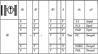


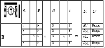

Figure 7.25. Situation 8 (far obstacle: approaching the goal)
This step concerns the development of rules, to define the expected behavior of the robot according to its intrinsic parameters: obstacles data, target data and the robot movement instructions. Every combination of input variable values results in an action to the output variables. In total we get 80 fuzzy rules.
- – Defuzzyfication
The controller output is obtained by the defuzzification method called “weighted average”. This step transforms the command values of the real area (physical variables). This choice is generally conditioned by a compromise between the implementation ease and calculation performance (Pelletier 2000). We have used the center of gravity method determined by the following relation:

with
- – m: number of rules;
- – Z: variables of command;
- – µ: membership function.
7.6. Simulation and results
To implement the control architecture developed and described in previous sections, in this part we have implemented a local planner based on sensory information in a constrained and unknown environment to navigate the robot to a final destination. The mobile robot must be able to make decisions about the movements to be made according to variations in the environment; the program implemented locates the robot, the target, and determines the position of the obstacles in relation to each moment during navigation. This program also allows the monitoring of places of evolution and transmits information about the environment to the robot. The implemented simulator is based on the hybridization between MAS and fuzzy logic, in order to benefit from the advantages of each methodology. Using programming tools (Borland 5 c ++), this implementation allows us to visualize the results of the navigation of the mobile robot in different environments.
Several navigation tests have been simulated for different configurations of the target and robot in different environments (simple and complex environments). Figures 7.26 and 7.27 show the path taken by the robot to reach its target; Figure 7.26 with environment 1 and environment 2 and Figure 7.27 with environment 4 and environment 5, which are more complex than environments 1 and 2.
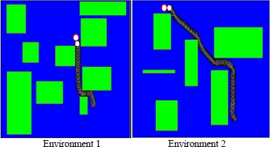
Figure 7.26. The robot, in environments 1 and 2, reaches the target (all obstacles are avoided). For a color version of this figure, see www.iste.co.uk/chelouah/optimization.zip

Figure 7.27. The robot reaches the target in complex environments (environments 3 and 4) (all obstacles are avoided). For a color version of this figure, see www.iste.co.uk/chelouah/optimization.zip
The navigation approach adopted deals with robot blockage situations. In the case of a deadlock situation, the fuzzy controller sends a deactivation message to the locomotion agent to stop the robot, as shown in Figure 7.28.

Figure 7.28. The robot in a deadlock situation. For a color version of this figure, see www.iste.co.uk/chelouah/optimization.zip
Through these figures, we note the performance and efficiency of the adopted approaches (MAS and fuzzy logic) in the mobile robot navigation in complex and changed environments. The robot always manages to reach its target without colliding with obstacles or with the walls of the environment, while choosing the shortest path.
7.7. Conclusion
The design of a control architecture is a central problem in a project of realization of an autonomous mobile robot. In the absence of a universal solution that eclipses all others, it is essential to detail and justify the design process that has lead to the proposed solution.
In this chapter, we presented a solution to this problem by developing a navigation control architecture based on the hybridization of two artificial intelligence approaches: MAS and fuzzy logic. More details have been given in this chapter about the inference mechanism. The overall behavior of the robot during its navigation is identified in two essential procedures: the obstacle avoidance procedure (there are seven situations: situation 1, …, situation 7) and the approaching goal (there is one situation: situation 8). These procedures are presented by some rules of navigation, using fuzzy logic as advanced tool for navigation.
The simulation results obtained are satisfactory because the robot manages to reach its target, despite the complexity of the environment in which it is located. This leads the way to the adaptation of our architecture developed for navigation in a dynamic environment (moving obstacles). The extension to distributed mobile robotics could be achieved because the chosen architecture is able to manage communications between other robots by adding specific agents, ensuring the link with other robots, which widens the field of application of mobile robotics. So design a multi-agent system organized by subsystems, where each robot is a subsystem multi agent.
7.8. References
Adv, J. (2018). Fuzzy logic as efficient tool to the navigation of mobile robot in an unknown dynamic environment. Robot Systems, 10(37), 1–7.
Ahmad, Z. and Ghanavati, M. (2012). Navigation of mobile robot using the PSO particle swarm optimization. Journal of Academic and Applied Studies, 2(1), 32–38.
Ahmadzadeh, H. and Masehian, E. (2015). Modular robotic systems: Methods and algorithms for abstraction, planning, control, and synchronization. Artificial Intelligence, 223, 27–64.
Alajlan, M., Koubaa, A., Chaari, I., Bennaceur, H., Ammar, A. (2013). Global path planning for mobile robots in large-scale grid environments using genetic algorithms. In International Conference on Individual and Collective Behaviors in Robotics (ICBR’2013), Sousse, Tunisia.
Benbouabdallah, K. and Qi-dan, Z. (2013). A fuzzy logic behavior architecture controller for a mobile robot path planning in multi-obstacles environment. Research Journal of Applied Sciences, Engineering and Technology, 5(14), 3835–3842.
Buhler, H. (1994). Réglage par la logique floue. Presses polytechniques et universitaires romandes, Lausanne, Switzerland.
Capi, G., Kaneko, S., Hua, B. (2015). Neural network based guide robot navigation: An evolutionary approach. Procedia Computer Science, 76, 74–79.
Chaaria, I., Koubaa, A., Bennaceur, H., Ammar, A., Trigui, S., Tounsi, M., Shakshuki, E., Youssef, H. (2014). 5th International Conference on Ambient Systems, Networks and Technologies (ANT): On the adequacy of Tabu search for global robot path planning problem in grid environments. Procedia Computer Science, 32, 604–613.
Chaib-draa, B. (1994). Distributed artificial intelligence: An overview. In Encyclopedia of Computer Science and Technology, Ken, A., Williams, J.G., Hall, C.M. and Kent, R. (eds). Marcel Dekker Inc., New York.
Chaib-draa, B., Jarras, I., Moulin, B. (2001). Multi-agent systems: General principles and applications. In Agent and Multi Agents System, Briot, J.P. and Demazeau, Y. (eds). Hermes, Ottawa, Canada.
Darwish, H. and Joukhadar, A. (2018). Using the Bees Algorithm for wheeled mobile robot path planning in an indoor dynamic environment. Journal Cogent Engineering, 5(1), 1426539.
Dudek, G., Jenkin, M.R., Milios, E., Wilkes, D. (1996). A taxonomy for multi-agent robotics. Autonomous Robots, 3(4), 375–397.
Elfakharany, A., Yusof, R., Ismail, Z. (2020). Towards multi robot task allocation and navigation using deep reinforcement learning. Journal of Physics, 1447, January.
Engedy, I. and Horváth, G. (2009). Dynamic artificial neural network based mobile robot motion and path planning system. 6th IEEE International Symposium on Intelligent Signal Processing, Budapest, Hungary.
Faisal, M., Hedjar, R., Al Sulaiman, M., Al-Mutib, K. (2013). Fuzzy logic navigation and obstacle avoidance by a mobile robot in an unknown dynamic environment. INTECH International Journal of Advanced Robotic Systems, 10(1), 1–7.
Farhad, B., Sepideh, N.N., Morteza, A. (2018). Mobile robots path planning: Electrostatic potential field approach. Expert Systems with Applications, 100, 68–78.
Ferber, J. (1995). Les systèms multi-agents : vers une intelligence collective. InterEditions, Paris, France.
Gul, F., Rahiman, W., Sahal, S., Alhady, N. (2019). A comprehensive study for robot navigation techniques. Journal Cogent Engineering, 6(1).
Holzmann, F., Bellino, M., Kolski, S., Sulzmann, A., Spiegelberg, G., Siegwart, R., (2005). Robots go automotive – The SPARC approach. IEEE Intelligent Vehicles Symposium, Proceedings, 478–483.
Iñigo-Blasco, P., Diaz-del Rio, F., Carmen Romero-Ternero, M., Cagigas-Muñiz, D., Vicente-Diaz, S. (2012). Robotics software frameworks for multiagent robotic systems development. Robotics and Autonomous Systems, 60(6), 803–821.
Khatib, O. (1986). Real-time obstacle avoidance for manipulators and mobile robots. International Journal of Robotic Research, 5(1), 90–98.
Latombe, J.C. (1999). Motion planning: A journey of robots, molecules, digital actors, and other artifacts. The International Journal of Robotics Research, 18(11), 1119–1128.
Lin, K., Li, Y., Sun, J., Zhou, D., Zhang, Q. (2020). Multi-sensor fusion for body sensor network in medical human–robot interaction scenario. Science Direct, Information Fusion, 57, 15–26.
Lozano-Pérez, T. (1983). Spatial planning: Configuration space approach. IEEE Transactions on Computers, C-32(2), 108–120.
Matoui, F., Boussaid, B., Metoui, B., Frej, G.B., Abdelkrim, M.N. (2017). Path planning of a group of robots with potential field approach: Decentralized architecture. IFAC-PapersOnLine, 50(1), 11473–11478.
Moreau, J. Melchior, P., Victor, S., Aioun, F., Guillemard, F. (2017). Path planning with fractional potential fields for autonomous vehicles. IFAC-PapersOnLine, 50(1), 11433–11438.
Moulin, B. and Chaib-draa, B. (1996). An overview of distributed artificial intelligence. In Foundations of Distributed AI, O’Hare, G.M.P. and Jennings, N.R. (eds). John Wiley & Sons, Chichester, UK.
Nguyen, D. and Widrow, B. (1989). The truck backer-upper: An example of self-learning in neural networks. Proceedings of the International Joint Conference on Neural Networks, 2, 357–362.
Pan, J. and Dinesh Manocha, D. (2015). Efficient configuration space construction and optimization for motion planning. Engineering, 1(1), 46–57.
Pandey, A. (2018). Different nature-inspired techniques applied for motion planning of wheeled robot: A critical review. International Journal of Advanced Robotics and Automation, 3(2), 1–10.
Pelletier, F.J. (2000). Review of metamathematics of fuzzy logics. The Bulletin of Symbolic Logic, 6(3), 342–346.
Qiongbing, Z and Lixin, D. (2016). A new crossover mechanism for genetic algorithms with variable-length chromosomes for path optimization problems. Expert Systems with Applications, 60, 183–189.
Reignier, P. (1994). Pilotage réactif d’un robot mobile : étude de lien entre la perception et l’action. Thesis, Institut national polytechnique de Grenoble, France.
Schwartz, J.T. and Yap, C.K. (1987). Algorithmic and Geometric Aspects of Robotics. Lawrence Erlbaum Associates, Hillsdale, NJ, USA.
Wijesoma, W.S., Khaw P.P., Teak, E.K. (2001). Sensor modeling and fusion for fuzzy navigation of an AGV. International Journal of Robotic and Automation, 16(1), 14–25.
Yahyaoui, K., Debbat, F., Khelfi, M.F. (2006). Conception d’une architecture de contrôle pour la navigation autonome d’un robot mobile. Conférence Internationale sur l’Ingénierie de Électronique, Université des sciences et technologie d’Oran Mohamed Boudiaf, Algeria, 28–29 May.