
6
Wi-Fi and 5G
5G has not yet been standardized, and this standardization is not expected to come into force before 2020. However, it is possible, even now, to obtain a fairly clear picture of what 5G will offer, by looking at the numerous R&D projects in this field. Figure 6.1 represents the different steps to achieve 5G. Starting from the origin of mobile networks, there was analog circuit-switched 1G, then digital circuit-switched 2G, followed by digital packet-switched 3G, with the exception of operator voice signals. With 4G, we see the move to 100% IP technology, even for voice signals, and 4G also handles multimedia applications. Finally, 5G offers increased data rates, but above all, allows billions of things to be connected.
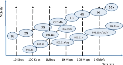
Figure 6.1. The different wireless solutions
In Figure 6.1, we also see two other directions taken by mobile networks. The first is WiMAX, normalized by the IEEE 802.16 working group. However, this initiative failed – not so much from the technological standpoint, but definitely so from the political perspective, given the power of mobile networks operators who have chosen the 3GPP as a standardizing body, and the trend visible across 1 to 5G. The second direction is Wi-Fi, which exhibits very promising behavior, and sells hundreds of millions of components every single day. The Wi-Fi family is currently expanding to include increasingly high data rates and increasingly longer ranges. We are going to examine these new standards in detail in this chapter.
6.1. 3GPP and IEEE
The 3GPP and the IEEE are the two main standardization bodies. The different standards are marked in Figure 6.2. It should be noted that LTE (Long Term Evolution) is the last version of 3G, and does not belong to 4G. The 4G series begins with LTE-A (LTE-Advanced), which is the first 100% IP standard of its kind. In LTE, telephone signals still use GSM or CDMA – i.e. 2G in digital circuit-switched mode. However, it is possible to use telephony in VoIP mode over the data part of the LTE interface. In this case, the voice signals are referred to as VoLTE (Voice over LTE).

Figure 6.2. The two major wireless solutions and their convergence
Figure 6.2 shows the convergence of the two techniques developed by the 3GPP and the IEEE. In Chapter 1, we saw that only by combining these two technologies will we be able to supply the capacity that users today demand. Wi-Fi is becoming the offloading technique for 4G/5G – i.e. it is used to relieve the load on the 4G/5G networks, with Wi-Fi antennas being used alongside the mobile network antennas. Predictions are that offloading will come to represent three quarters of the data rates of mobile terminal connections. In addition, Wi-Fi represents high data rates across hotspots, but using the Internet rather than the mobile access networks. The version of Wi-Fi for the world of telecommunications can take a variety of forms. For the moment, Wi-Fi Passpoint is the version which seems to be the most popular. Passpoint is championed by the Wi-Fi Alliance, which has already shown its strength, promoting the use of Wi-Fi through proving the conformity of products. However, other solutions are also being studied by the standardization organizations, such as replacing Wi-Fi with LTE antennas and equipping all terminals and servers with LTE ports, referred to as Home eNodeB (HeNB). We shall see that this solution fits into the context of software networks, with the dawn of software LTE.
We shall begin by examining the new generations of Wi-Fi, which have the necessary capacity to deal with the exponentially-increasing demand of users.
6.2. New-generation Wi-Fi
The new-generation of Wi-Fi began with the IEEE 802.11ac standard, which was released in late 2013 and achieves data rates higher than 1 Gbps. This minimum value of 1 Gbps marks the new generation of Wi-Fi. The IEEE 802.11ac standard, which we shall go on to examine in detail, is supplemented by IEEE 802.11ad, which uses a new frequency band: 60 GHz. This solution is primarily designed for the inside of buildings, and for very directional use outside. Indeed, at these frequencies, the signal is very vulnerable to interference from rain, dust and, of course, obstacles. Thus, to use it outside, we need a direct path to the access point, with good weather conditions if possible, or at least a short enough distance for the data rate to remain correct, even in the presence of rain or fog.
The new generation continued with IEEE 802.11af, which uses cognitive radio – i.e. the possibility of using frequencies for which there is a proprietor (also known as a primary) who is not using them at a given time. For this to work, we must either drastically limit the range so as to remain in an environment without conflict with the primary, or have a server which records the use of frequencies and enables the cognitive access points to discover the usage sites and use the frequencies with no danger of interference. The IEEE 802.11af standard uses television bands, and is known as TVWS (TV White Space) or sometimes Super Wi-Fi.
There are still numerous developments under way in the field of new-generation Wi-Fi, such as IEEE 802.11ah, which pertains to long-range Wi-Fi of around a kilometer, but with much lower data rates. Its uses are mainly in the domain of the connection of “things”, such as intelligent electricity meters or healthcare equipment. Numerous other standards are in the reflection phase; one of these is IEEE 802.11ax, which is an improvement of IEEE 802.11ac, with four times the capacity.
6.3. IEEE 802.11ac
IEEE 802.11ac is a version of Wi-Fi designed to surpass 1 Gbps, using multiple antennas, which can run simultaneously but in separate sectors. Two mutually complementary solutions have been put in place to obtain the target data rates. The first, which is fairly simple, consists simply of increasing the capacity of the transmission channel using the 5 GHz band, which is much freer than the 2.4 GHz band. The range of this higher-frequency band is a little less. In addition, obstacles hamper the signals somewhat. However, the available bandwidth is 200 MHz, which is much greater than the 83.5 MHz assigned to the 2.4 GHz band, which enables us to have Wi-Fi channels whose band is 80 MHz, and optionally, 160 MHz.
The second solution pertains to the directionality of the signals emitted, using a set of specific antennas. This technique involves allowing the transmission of several communications on the same frequency, but in different directions. There is spatial multiplexing, hence the name of this technique: SDMA (Space Division Multiple Access). Figure 6.3 illustrates this technology.

Figure 6.3. SDMA
SDMA technology uses transmission techniques allowing us to direct the signals – better known as “beamforming” – whereby the signals are orientated in a specific direction, thus giving rise to directional antennas. The set of antennas, also known as virtual antennas, enables us to generate several directional antennas simultaneously, which facilitates communication with multiple clients at the same time. The technique used in IEEE 802.11ac is also called PU2RC (Per-User Unitary Rate Control). 802.11ac-conforming antennas are also able to deliver MU-MIMO (Multi-User MIMO) – that is, to connect several pairs of clients to one another, using several antennas simultaneously on the same frequency, whilst minimizing interference. In other words, each directional antenna can be replaced by several antennas with the same directionality, using the same frequency to carry out communications in MIMO mode.
With this technology, we are able to multiply the data rate by the number of virtual antennas. In the example shown in Figure 6.3, the two physical antennas each give rise to three virtual antennas, which is a total of six virtual antennas. These six antennas mean that six simultaneous communications can be established. With these six antennas, we can also establish three 2×2 MIMO communications (two virtual antennas communicating with two antennas on a remote machine). We can just as well have three simultaneous communications: one 3×3 MIMO communication, one 2×2 MIMO communication, and a one-way communication.
The peak data rate reaches 250 Mbps per virtual antenna. With four physical antennas, each bearing three virtual antennas, we obtain twelve virtual antennas. Thus, the total data rate is 3 Gbps. Also, if the bands used are wider – say, 80 MHz instead of 20 MHz – then theoretically we can achieve over 10 Gbps. In actual fact, as for all Wi-Fi access points, the peak data rate is only achieved in exceptional cases, where there is no external interference and the clients are located very near to the antenna. In reality, the nominal data rates are often divided by at least a factor of 2, but often much more, to obtain the real data rates.
The group IEEE 802.11ac, with 433 Mbps per antenna over an 80 MHz band and a MIMO with two antennas per client, delivers 866 Mbps per connection with a terminal. With four physical antennas, we achieve over 3 Gbps. With a bandwidth of 160 MHz, the data rate is doubled. The standard specifies that there may be up to eight spatial sectors, which again doubles the data rate. Evidently, these reported figures are peak data rates, which are only very rarely achieved in reality. As is the case with all Wi-Fi solutions, fallback rates become necessary when the conditions are not ideal. Compatibility with existing standards also requires the adaptation of data rates to conform to standards which are not compatible with IEEE 802.11ac.
The aim with the new IEEE 802.11ax standard is to further increase the data rate by using more numerous and more directional antennas.
6.4. IEEE 802.11ad
The IEEE 802.ad standard is completely new, with frequencies in the range of 60 GHz. This standard is championed by a group of manufacturers: the WGA (Wireless Gigabit Alliance). The name of the product, which is likely to become standard in personal area networks, is WiGig. However, the basic product could be tri-band WiGig, operating simultaneously on the 2.4 GHz, 5 GHz and 60 GHz bands, and therefore able to adapt to the environment. The peak data rate is 7 Gbps. The range in the 60 GHz band is less than 10 meters, so this network is said to belong to the category of PANs (Personal Area Networks).
The channels used in the base mode correspond to 57.24 GHz, 59.4 GHz, 61.56 GHz and 63.72 GHz. The bandwidth is 2.16 GHz.
To compensate for the significant attenuation of the signal, IEEE 802.11ad requires directional antennas which can focus the radio beam within a 6° angle. With this very narrow beam, the IEEE 802.11ad standard is used outdoors between directional antennas with a direct view, or indoors but counting on ricochets to reach the addressee. Indeed, with a 6-degree beam, the connection between two machines is often complex. Fortunately, there is an option which enables us to direct the beam so that the two machines wishing to connect can communicate with one another.
Two applications of IEEE 802.11ad are mentioned in the standard. The first corresponds to wireless connections for peripheral computers, with the aim of doing away with the numerous cables which trail everywhere. This application also facilitates simple sharing of peripheral devices. The second application relates to consumer electronics, associated with wireless technology, such as stereo equipment, HD televisions, and online gaming systems.
6.5. IEEE 802.11af
The IEEE 802.11af technique pertains to a totally different method to increase the data rate: the use of cognitive radio. It consists of reusing frequency bands which are not being used at a time t in the television bands.
More generally, recent measurements show that, in spite of their scarcity and their high price, frequencies between 0 and 20 GHz are under-used – often less than 10%.
The only bands which are heavily used are those employed by telecom operators which, owing to the TDMA and CDMA techniques, exhibit excellent degrees of utilization. The bands reserved for TV channels, which are below 1 GHz, are particularly attractive to operators. These TV channels could be used by access points to achieve ranges of hundreds of meters. Such ranges demonstrate that Wi-Fi technology is capable of serving the needs of WiMAX and 4G clients.
The WiFi standard IEEE 802.11af – which must not be confused with IEEE 802.3af, or PoE (Power over Ethernet) – is called TVWS (TV White Space). The expression “white space” refers specifically to those frequencies which are not used by wireless television channels. The operational bandwidth for cognitive radio covers dozens of digital television channels. The data rates achieved by this method may be very high indeed. The name of the product is “White-Fi”, also sometimes called “Super Wi-Fi”.
One important question relates to the way in which cognitive radio is used. It is for each state to regulate this usage. The main solutions pertain to the way in which unoccupied frequencies are used. A number of solutions suggest themselves, depending on the coverage of the cognitive access point. If the band is not occupied at the access point’s location, it can be assumed that it is not occupied within a radius of a few meters of that point. This category includes Wi-Fi access points inside buildings with limited power, only covering the inside of the building. A second solution is to refer to a bandwidth management server, which knows where the bands are available. Thus, a common discipline needs to be used between the primary and secondary users. With this in mind, though, will TV operators manage to reach an agreement with Wi-Fi 802.11af users? Standardization work is being carried out in different working groups, such as IEEE P1900, with a view to proposing solutions acceptable for both parties. A third, more remote, solution could stem from the ability for each device to measure the interference and indicate to the secondary users whether or not they can exploit the frequency.
At the physical level, the method used in IEEE 802.11af is FSS (Fixed Subcarrier Spacing) with OFDM. The channels used in OFDM may or may not be contiguous – that is, they may belong to television channels that are directly beside one another or that are separated by active television channels.
A channel contains 64 bearers. Four channels may be selected, each operating at 6, 7 or 8 MHz. In the latter two cases, as the data rate per channel reaches 26.7 Mbps and given that, as with IEEE 802.11ac, we can have at least four directions in SDMA, the maximum base rate is 568.9 Mbps, with 8 MHz channels.
The bearer access technique is the same as with normal Wi-Fi. Service classes using an EDCA (Enhanced Distributed Channel Access) technique from IEEE 802.11e are available, and correspond to the four classes Background, Best-Effort, Video and Voice. A fifth, even higher, priority is added for spectrum-monitoring, to determine which channels could potentially be used.
6.6. IEEE 802.11ah
The IEEE is working on a new standard, apt for the connection of “things” – i.e. sensors or other small devices with low consumption and often minimal cost. This solution works in the non-licensed bands available below 1 GHz. The technique should enable us to connect a large number of things with low consumption. The sharing of the transmissions takes place in classic Wi-Fi mode, but with a much lower data rate and a much greater range, of up to 1 km. The things are grouped into clearly-defined sets so as to avoid too high a number of simultaneous accesses and so as not to lose too much in contention in CSMA/CD mode. In addition, IEEE 802.11h involves the use of classic techniques in the world of Ethernet to put stations on standby and reawaken them.
IEEE 802.11h introduces the function of relay, whereby certain things can connect through the relay, which decreases competition by limiting the number of objects attempting to transmit simultaneously. Relay increases the geographic scope of the things that can be connected and, at the same time, saves energy by having tasks managed locally by the relay. In the standard, the aim is not to create a mesh network, as the number of hops is limited to two.
Energy savings are also of crucial importance in the current context, where consumption is increasing exponentially, and the IEEE 802.11ah standard does take steps in this direction. For this purpose, the connected machines are divided into two classes: TIM (Traffic Indication Map) terminals and non-TIM terminals. TIM terminals periodically receive information about the traffic on the access point. Non-TIM terminals use the new mechanism TWT (Target Wake Time) to reduce the overhead of the signaling procedure.
TWT is a function which allows an access point to define a time, or a set of times, for certain terminals to have access to the communication bearer. The terminal and the access point exchange information including the allotted duration of the activity, to enable the access point to control any competition and clashes between competing terminals. The access point can reserve time periods for a terminal to transmit thanks to various protective mechanisms. The use of TWT is negotiated in advance between an access point and a terminal. The TWT mechanism is also used to reduce energy consumption, because stations using it can enter a semi-sleep state until their TWT comes around.
Another important mechanism in IEEE 802.11ah is the RAW (Restricted Access Window), which limits the number of terminals which have the right to use the access point. This limitation is achieved by putting the terminals into groups. Channel access is restricted solely to those terminals belonging to a given group, over the course of a set period of time. This mechanism helps reduce competition and avoid simultaneous transmissions from too high a number of machines which are unaware of one another’s presence.
The IEEE also defines a TXOP (Transmission Opportunity), wherein an access point and a client can carry out a set of exchanges during a reserved period. The purpose of this mode of operation is to reduce the number of competing channels, improve the efficacy of the channels by minimizing the number of exchanges and help extend the terminals’ battery life by minimizing their periods of activity; the rest of the time, the terminal is on standby.
The division of the coverage area of a Basic Service Set (BSS) into sectors, determining subsets of terminal machines, is called “sectorization”. It is done by a set of antennas or a set of directional antenna lobes to cover different sectors of the BSS. The goal of sectorization is to decrease contention and interference by reducing the number of terminals that can transmit simultaneously.
6.7. Small cells
“Small cells” is the term used to denote the new generation of cells of very small dimensions. There are numerous factors which weigh in favor of this solution, starting with reuse of frequencies, adaptation of the cells to the size of a dwelling, lowering of energy consumption, etc. Small cells are found in a variety of forms in network technology: femtocells, which correspond to a home; metrocells, which provide coverage in the street; hotspots, which are set up in public spaces; or picocells, for companies.
The main rollout should take place between 2016 and 2020. The first small cells appeared in 2010, and have become increasingly common from 2012 onwards. In certain countries, such as the United States and South Korea, there are at least three telecom operators already commercializing femtocells.
In this section, we begin by examining femtocells, which are devoted to connecting users in their homes and in the vicinity. We also present hotspots, followed by picocells, and finish up with a discussion of metrocells and microcells. We then go on to describe the Passpoint technology, which is able to bring together all of these smaller cells. In the next section, we shall look at backhaul networks, the aim of which is to connect small cells to the core network. Finally, we shall close this chapter by presenting some relevant aspects of Software Radio, Cognitive Radio and the new generation of cells.
Figure 6.4 represents a small-cell network and the backhaul network.

Figure 6.4. Small cells and backhaul networks
6.8. Femtocells
The solution advocated since release 9 of UMTS by the 3GPP to handle the enormous data rates of 4G is the use of femtocells. The fundamental ideas are fairly similar to the relay technique: so as not to have to construct a new, very dense network to connect the antennas, we use the fiber-optic infrastructure that has been in place since 2009 for very high data rate. In actuality, this optical network is not only designed to provide users with high data rates, but indeed to deliver the extremely high data rates proposed by 4G, as users cannot really tell the difference between a top-of-the-range ADSL modem and an optical modem, owing to the controls in place in the world of IP, and in particular, slow-start.
A femtocell is an antenna mounted on the user’s Home Gateway. It serves all potential clients who are within the antenna’s coverage area, which may be around ten meters, or indeed much more, depending on the obstacles and interference present. Thus, the femtocell is used both by the owner of the Home Gateway and by the visitors to the cell.
The obvious advantages offered by this technology are the multiplication of the cells and the densification of the network. Another very clear advantage is the drop in power of the devices which this technology facilitates. A maximum power of 100 mW seems to be the standard that is coming to pass; this power corresponds to the power required for an omnidirectional Wi-Fi transmission.
Figure 6.5 illustrates the way in which a femtocell works.

Figure 6.5. Operation of a femtocell
Conventional antennas are linked to the core network by BSC or RNC switches, corresponding respectively to 2G and 3G. The femtocell antenna is connected to a Femto-Gateway, which provides access to the core network. The connection between the Home Gateway and the Femto Gateway uses fiber-optic technology, and also often an ADSL connection. The connected terminals employ 3G, 3G+ (LTE) or 4G. The data rates are, as yet, fairly limited by radio constraints or the line to the Femto-Gateway, but by 2020, the data rates available to 4G/5G mobiles will have reached 100 Mbps.
Questions arise as to the usefulness of a Wi-Fi antenna, the possibility of a war between Wi-Fi and 4G or the supremacy of Wi-Fi at the center of the femtocell. In fact, there is little chance of 4G antennas completely replacing Wi-Fi antennas. For that to happen, all computerized devices, printers, PCs, multimedia equipment, etc., would need to have a 4G port. Thus, there is a high probability that the two systems will coexist, with each of them handling those devices which are most appropriate.
The numerous femtocell products which are coming on the market offer diverse, varied options, as illustrated in Figure 6.6. The Home Gateway is usually referred to as an “HNB” (Home NodeB) or HeNB (home eNodelB), provided it is available with a 3G or 4G antenna. Today, these boxes essentially serve to connect 3G/4G mobiles, enabling the operator to offer the client the possibility of using his/her 3G/4G mobile in a location where there is no signal.
The HNB/HeNB very often has two radio interfaces: Wi-Fi and 3G/4G. The telecom equipment is plugged into the 3G/4G antenna, and the computer equipment into the Wi-Fi. The fiber-optic or ADSL modem simultaneously transports the flows from both environments. The second solution shown in Figure 6.6 corresponds to the use of Wi-Fi to connect telecom equipment and computers. In this case, the 3G/4G frame is encapsulated in a Wi-Fi frame and decapsulated in the Home Gateway. The 3G/4G frame is then directed to the RNC for forwarding to the core network. This solution is called UMA (Unlicensed Mobile Access) in general, GAN (Generic Access Network) for 3G, and EGAN (Enhanced GAN) for 4G.

Figure 6.6. Access to the HNB
6.9. Hotspots
Hotspots are Wi-Fi access points whose purpose is to facilitate a high-data-rate Internet connection from a smartphone, tablet or PC. Situated in places with a great many people passing through, they are open to all clients who wish to connect, or sometimes only to those who have a subscription. If the access point is open, any and all clients can connect. However, in numerous countries, the operator of the access point must be able to monitor the clients, either in order to charge them for access or to preserve their information to locate the clients later on if the connection is used in the commission of a crime. Hotspots are located in rail stations, airports, shopping centers, at marinas and beaches, boutiques, etc.
Hotspots essentially use Wi-Fi technology and depend increasingly on telecom operators to handle their 3G/4G traffic to relieve the relay antennas which, today, are very often overloaded. This is the technique which we looked at earlier: offloading.
The difficulty for a hotspot is to manage to offer QoS to the clients’ applicational flows. More specifically, the capacity of the access point depends on how far away the client is and on the degree of interference: the further away a client is, the more the signal is attenuated and the greater is the risk of interference, and therefore the access point’s overall data rate degrades. In order to deal with these problems, Wi-Fi technology relies on oversizing. Still rarely available when many clients are connected to the same access point, oversizing should soon be introduced generally, thanks to new technologies which have reached maturity since 2014: specifically, IEEE 802.11ac, ad and af, which should help to ease communication.
In today’s world, operators use Wi-Fi for the purposes of offloading, but as the solution is not standardized, each operator has developed their own technique (although they are all fairly similar to one another). Since 2014, the technology championed by the Wi-Fi Alliance – Passpoint – has served as a common standard for all operators. This technology is described in detail a little later on.
Metrocells are small cells which are installed in the streets to handle the 3G/4G traffic of operators. They are the equivalent of femtocells, but instead of being situated in the private domain of the home, they are in the public domain. They need to cover a surface area slightly larger than femtocells. Indeed, as there are fewer obstacles in the public domain than in the home, the clients should be able to connect, provided they have a direct view of the access point. The size of the cell is a few tens of meters. A network of metrocells is illustrated in Figure 6.7, with the metrocells serving for offloading – i.e. taking the strain off the main 3G/4G antenna.

Figure 6.7. A network of metrocells
The purpose of these metrocells is to always allow offloading – i.e. to handle 3G/4G communications for the operators in order to alleviate the workload of the large antennas. The metrocells are either interconnected to form a mesh network, or connected by optical fibers, but the cost of implementing the latter solution may prove prohibitive. They may also be linked by PLC (power-line communication) as in Figure 6.7, where the access points are mounted on lampposts.
6.10. Microcells
Microcells are designed for use by companies. They can serve the company’s internal network provide access to its intranet whilst also allowing telecom equipment (smartphones, tablets, etc.) to connect directly to the operators’ networks. In other words, they must deliver two forms of access simultaneously, which may be achieved by two distinct SSIDs on the same access point, or else by using virtualization. By virtualization, we are able to put in place two virtual access points on the same physical access point. In both cases, the two networks – the company’s and the network that connects to the operator network – need to be perfectly separated from one another; this is known as isolation of the two networks.
Microcells also use Wi-Fi techniques, and rely on the new standards to deliver the quality of service necessary to handle telephony and video with a good level of quality.
Engineering plays a very important role for the installation of microcells, because a company needs to cover all of its offices, workshops and boardrooms, with all of the problems caused by walls, floors and other obstacles. It is essential, in this context, to minimize interference between the access points, whilst ensuring overall coverage with as high a data rate as possible.
6.11. Wi-Fi Passpoint
Passpoint is an architecture proposed by the Wi-Fi Alliance. The Wi-Fi Alliance was set up when Wi-Fi was first proposed with the aim of promoting this technology. It has had a significant part to play in the success of Wi-Fi and the introduction of various standards, such as WPA2, which offers high security in Wi-Fi networks, or the introduction of priorities with IEEE 802.11e.
Passpoint is a solution which helps to relieve the workload of 3G/4G antennas by offloading, giving users the option of connecting in a way that is totally transparent to the 3G/4G networks, using Wi-Fi networks. In other words, the client will not know how s/he is connected to the operator network: by a BTS, a NodeB or an eNodeB or by a Wi-Fi access point (hotspot, femtocell, microcell, metrocell, etc.).
In home or business environments, connection to a Wi-Fi network is generally made automatically once the user has entered the authentication data upon first connecting to the network. When s/he is connected to the access point and authorized to enter into the network, s/he is subject to the rules established by the IT manager or the owner of the access point. Once recognized, his/her terminal automatically joins the access points to which it connects regularly, without intervention on his/her part.
The connection to most hotspots is often different to that which is described above. In a public place where there are many networks, the clients often have to begin by choosing the network to which they wish to connect, and then identify themselves to the access point. Finally, in most cases, they need to enter authentication data. There are solutions in existence to simplify network selection and automatically make the connection whilst still ensuring good security, but these solutions are often restricted to a small number of networks and are very rarely available abroad.
Wi-Fi Passpoint technology fundamentally changes the use of public hotspots. It is a general solution which all hotspot operators can apply, which helps to overcome the limitations of the proprietary, non-interoperable solutions offered by current providers. A program, installed on certified devices, automatically manages the network connection, authentication, authorization and underlying security in a manner which is totally transparent to the user. This solution works with all Passpoint networks.
First and foremost, Passpoint takes care of the discovery and selection of a network. The terminal machines discover and automatically choose the network to which to connect on the basis of preferences determined by the users, policies defined by the operators and the availability of the network. These characteristics are based on the IEEE 802.11u standard.
The network connection takes place seamlessly – i.e. without the user having to do anything at all. It is no longer necessary for the terminal to be on an active list of access points to which the user agrees to connect. Nor is it necessary to enter account information into a browser. Passpoint uses a consistent interface, and the connection process is automatic. In addition, the choice of peripheral device can always be made automatically for multiple types of identification information. Passpoint uses SIM (Subscriber Identity Module) cards for authentication; these cards are also very widely used in modern-day cellphone networks. Passpoint also uses username/password combinations and certificates. No intervention on the part of the user is needed to establish a connection to a trusted network.
All Passpoint connections are secured with WPA2-Enterprise for authentication and connectivity, thus offering a level of security comparable to that of cellular networks. Passpoint improves upon WPA2-Business, adding functions capable of containing the known types of attack in deployments for public Wi-Fi networks.
Passpoint can also be used to instantaneously open accounts when the user does not have a subscription to a telecom operator. This process is also standardized and unified for the establishment a new user account at the access point, using the same account-creation method employed by all Wi-Fi Passpoint service providers.
Passpoint creates a global platform centered on four protocols based on EAP (Extensible Authentication Protocol). Standardized and supported by all manufacturers in the area of security, this protocol is very widely employed today. The authentication methods EAP-SIM, EAP-AKA and EAP-TLS enable mobile operators to use the same authentication solutions for cellular and Wi-Fi.
In addition to ease of use because of transparent authentication, Passpoint offers numerous advantages to service providers and users – in particular, the following:
- – internet for electronic devices without a browser. Passpoint’s authentication method does not require a browser, facilitating the use of electronic devices such as cameras, onboard devices in cars, connected objects and, more generally, all “things” connected to the Internet;
- – simplicity of connection and creation of new subscriptions, whether to attach them to an existing account or introduce new services. The automation of the authentication process and the security of the connection make Passpoint small-cell access an attractive solution for content providers and manufacturers of content-oriented terminals, such as e-readers. Occasional users of Wi-Fi can use prepaid subscriptions, with the model being similar to that used by mobile operators.
Service providers are increasingly eager to protect their subscribers’ paying content. In order to do so, they need to know who receives that content. Passpoint authentication enables service providers to verify identity, to have access to the subscribers’ rights and to offer premium-quality content for subscribers connected to their home network, a company network or public access points.
Passpoint hotspots offer service providers transparent roaming to other operators’ networks. To activate roaming, the service operators first need to establish mutual roaming agreements, covering access validation and charging. Roaming is based on a single protocol for network selection and user authentication in the hotspot.
Once roaming between two service providers is activated, Passpoint devices can connect automatically either to the network of their own service provider or to that of the other, using the same procedure. In all cases, the Passpoint client recognizes the access point as belonging to the list of available networks and establishes a connection automatically, as happens with roaming for cellphones.
The new functions are activated only if the access point and the client’s device are Passpoint-compatible. The Passpoint certification program run by the Wi-Fi Alliance ensures this compatibility. In addition, Passpoint supports connectivity with non-Passpoint devices.
Clients with valid identification data and using an appropriate EAP method can connect to Passpoint access points. Clients who do not have identification data appropriate for EAP methods have to use an open system, based on authentication in a browser, where WPA2 may not be needed. In this case, security is not guaranteed.
Passpoint clients can connect to any existing Wi-Fi network. However, Wi-Fi clients will not necessarily be able to use Passpoint functions and services. For example, standard hotspots offer no security of connection, whereas Passpoint automatically implements WPA2 encryption.
Wi-Fi Certified Passpoint is a certification program offered by the Wi-Fi Alliance, aimed at both the access points and the clients’ terminals. Just as for Wi-Fi equipment, it ensures interoperability of the devices and terminals.
In Figure 6.8, we illustrate the different types of connections that can be made by a mobile in a Passpoint environment.
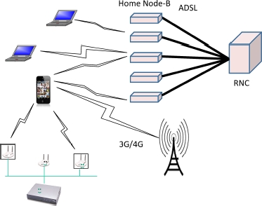
Figure 6.8. The integration of 3G/4G/5G and Wi-Fi access
In Figure 6.8, three types of connections are possible: a connection with the NodeB, which is the typical case of connection of a 3G/4G terminal; a connection with a hotspot which is, itself, connected to a Wi-Fi controller; and a connection with one or more HNBs (Home Nodes-B), located in domestic environments. It would also be possible to add metrocells, which are similar to femtocells but situated in public spaces – e.g. a street – instead of in private areas. The connection choices are made by the Passpoint technology, which is based on a Cloudlet situated near to the access points. The power of the Cloudlets becomes essential in this scenario, because the number of actions increases with the possibility of handovers between two of the access points, establishing multi-paths if a user’s data stream can be channeled through several access points simultaneously, and finally, managing multiple technologies by replacing certain Wi-Fi access points with connections such as Bluetooth, ZigBee or any other solutions available on the market.
6.12. Backhaul networks
Backhaul networks form the intermediary networks between the access networks to which the clients are connected and the core network. Such backhaul networks are becoming increasingly important, because small-cell technology requires a very large number of connections with all access points, instead of concentrating the connections on a small number of large antennas. It can be said that, up until now, backhaul networks have essentially consisted of links between DSLAMs and the core network, or between Nodes-B and the core network. Most typically, these networks use Gigabit Ethernet or MPLS technology.
The solution developing with small cells pertains to mesh networks, or networks of access points, in which the boxes are directly interconnected. For this purpose, mesh access points have two Wi-Fi ports: one to communicate with the neighboring access points, and the other to connect the clients. A client wishing to connect plugs into one access point, which transmits the packets to the neighboring access point, which in turn transmits them to its neighbor, and so on until they reach the core network, using an optical fiber or an xDSL modem. Typically, the access points are connected to one another by Wi-Fi, but other solutions are developing, with longer ranges, as we shall see.
Figure 6.9 shows a conventional configuration for a backhaul network. The small cells are connected to a “Small Cell Backhaul Aggregation” station, which harvests the data streams from the different cells and aggregates them, forwarding them on to the core network, either by fiber-optic or by wireless beams. The flows are directed to switches in the RAN (Radio Access Network), which are, themselves, connected to a switch in the core network. This link is often made using very-high-data-rate MPLS technology.

Figure 6.9. A backhaul network
The connections between the access points and the aggregators, or between the access points and the first RAN switch, increasingly frequently use wireless connections with a very high data rate, of several gigabits per second at high-frequency bands – e.g. the 60 GHz band. The major disadvantage to using these frequencies is that there must be a direct view and favorable weather conditions. Indeed, signals on these frequencies, which are sub-millimetric, are disturbed by drops of water and dust in the atmosphere. More specifically, the connection can use the 45 GHz, 57–64 GHz or 70–80 GHz bands, or even around 105 GHz. Seemingly, the most popular band is 60 GHz, for a variety of reasons: the bandwidth available, data rates countable in gigabits per second, low interference (because the connections are highly directional), low latency, small size of the components and antennas, and finally, a low production cost. The drawback to using this band is that two communicating antennas cannot be more than a kilometer apart, so as to avoid excessive losses.
6.13. Software radio and radio virtual machine
Undoubtedly cognitive radio represents one of the greatest revolutions of this new millennium. It facilitates much better use of the spectrum of radio frequencies, which is generally very poorly exploited. However, optimal use of the spectrum would be impossible without a certain number of other, parallel developments, which we shall now go on to discuss. We have already encountered this technology in TVWS (TV White Space) Wi-Fi in the IEEE 802.11af standard, pertaining to the use of unoccupied television bands.
Software radio, or SDR (Software-Defined Radio), defines a radio transmitter or receiver which is in software, rather than hardware, form. The implications of such technology are evident, because the characteristics of the radio interface can be modified infinitely without any technical problems at all; users will have the interface they need at a given time t, and a completely different interface at time t + 1. Obviously, a certain amount of hardware is needed to perform the computations of encoding, modulation and filtering, and for the transmission itself.
The computational power may be hosted on the device itself, or – as we have seen – in the mobile Cloud, in a local Cloudlet, a regional Cloud or even a central Cloud.
At present, progress in the area of this technology is being made very rapidly, because it is possible to condense all the computations for a large number of access points to a single machine. Nowadays, we are seeing the emergence of a particularly interesting, attractive solution: using a single antenna for all radio communications. The signal is sent to the appropriate virtual machine for processing. In other words, at certain times the antenna may receive Wi-Fi signals, and then at other times signals from a 3G communication, then 4G, then a TV signal, then Zigbee, and all of it is handled by virtual signal-processing machines.
The Cloud, once again, is important in these technological advances, and we can clearly see the amount of power and memory that are needed to support the necessary software machines. However, sometimes, there is insufficient power to process the signals in real time if the transmission rate increases. This is the reason for the current drive toward concretization – i.e. the opposite of virtualization. Software is transformed into hardware, using reconfigurable microprocessors. Whenever a specific program is needed, a hardware version of it is created, which increases the processing speed 100-fold. As the process of transforming the hardware is, as yet, relatively slow, we generally need several reconfigurable processors in order to offer real-time applications: whilst one processor is transforming, the others are running.
In Figure 6.10, we have represented what can likely be expected from software technologies in the world of radio over the coming years. The objectives are plotted on the basis of the flexibility that software radio can offer and the intelligence offered by cognitive radio.

Figure 6.10. The different advances made in the field of software radio
Thanks to these technologies, it is predicted that data rates will increase by a factor of 1000 within the next ten years.
6.14. 5G
5G is 4G’s successor. It is likely to be 2020 before it is standardized, and a few years after that before it begins being commercialized. The first major development which it offers regards the peak data rate, which should be between 1 and 10 Gbps. The main characteristic is the Internet of Things – “things” essentially being medical devices, household appliances or objects and sensors.
The characteristics of 5G contain numerous key terms, including:
- – UWB (Ultra Wide Band): use of a very wide spectral band, which can be purchased from states or used in cognitive radio;
- – smart antennas: antennas capable of operating with diverse encoding techniques, and also practically in any frequency;
- – small cells: as we saw earlier, small cells help to exponentially increase data rates by reusing the available frequencies;
- – software-based approach, using virtualization: this approach is widely used with this new generation of technology. In our coming discussion, we shall look at several examples of virtualization, but this technology is also encountered in at least three main techniques:
- - software-defined radio,
- - software-defined networking,
- - seamless combining of wide-band networks;
- – virtualization: virtualization also takes place in the devices themselves, such as:
- - HLRs, VLRs, eNodeB, RANs,
- - Cloud-RANs;
- – multi-access, multihoming, multi-technology and multi-route, which are technologies that are developing in the form of products available since 2014;
- – D2D (Device to Device), D2D2D, mesh networks, which represent simplified access techniques for ease of access, reduced energy consumption and reduced cost of connection.
Figure 6.11 represents several situations that can be handled by 5G. Starting on the left-hand side of the figure, we see multi-hop communications: the terminal is too far away from the NodeB, and the signals pass through intermediary machines in order to reach the antenna. This solution helps to limit the number of antennas whilst covering a large geographical area. Mesh networks or ad hoc networks provide this type of service, using algorithms to route the signals between the different terminals.
Next, we see D2D (Device to Device) – i.e. direct communication between two terminals without going through an antenna. This is a very eco-friendly solution, as it saves energy, minimizing the data rate of the system and thus decreasing electromagnetic pollution. Then, we find high-reliability solutions, whereby one path to reach the antenna can be replaced by another path almost instantaneously. Next, the figure shows connections to machines, for M2M (Machine-to-Machine) or M2H (Machine-to-Human) communication. The connection of things is also represented by medical devices, household appliances or other items. The figure also illustrates the connection to an intermediary relay to reach the main antenna. Indeed, as the energy expenditure depends on the square of the distance, it is very much to our advantage to use devices with short ranges.
Next, in the same figure, we see the problem of high density – e.g. the coverage of a stadium holding 100,000 people, with each spectator being able to enjoy a data rate of around 10 Mbps. The total data rate of 1 Tbps, in this scenario, could easily be delivered by an optical fiber, but the difficulty lies in the distribution of that capacity wirelessly. 4G and 5G technologies on their own are incapable of delivering such performances: we would need either extremely small cells or extremely high bandwidths.
Finally, Figure 6.11 shows a Cloud, which is one of the crucial elements – in fact, the very center – of 5G technology, in forms that have yet to be determined. However, we can confidently state that the algorithms will be decoupled from the devices, and will run on Clouds of greater or less power, situated more or less near to the user.

Figure 6.11. The different 5G access solutions
In summary, 5G networks should facilitate the integration of multiple wireless/mobile networks, which should allow for all classic applications and those of future society. This generation should also provide solutions to numerous problems; a few examples will be mentioned below. Most solutions will be heavily dependent on virtualization. The main problems are expressed by the following questions:
- – how can we avoid having too great a number of access points?
- – how can we avoid too cumbersome a cable infrastructure if numerous operators have developed small-cell infrastructures?
- – how is it possible to ensure quality of service in these overlapping and interlocking networks?
- – how can the backhaul networks ensure continuity between heavily-virtualized endpoints of the network and the core network, which is, itself, virtualized?
As stated many times, virtualization is one of the main solutions to the problems posed by fifth-generation technology. Looking first at the peripheral devices, connections can be gathered together on virtualized shared access points, so as to avoid having to deploy a physical access point for each small cell and each operator. The virtualization of a Wi-Fi access point is illustrated in Figure 6.12. The physical antenna is shared between all the virtual access points. The physical box which contains the virtual machines has a hypervisor, upon which the virtual machines are founded. Each virtual access point is in one of those virtual machines. The characteristics of the access points may be totally different from one another. Evidently, it is possible to replace the Wi-Fi access point with a 3G/4G base station which, if we employ virtualization, can actually become several base stations.

Figure 6.12. Virtualization of a Wi-Fi access point
Similarly, an HNB (Home NodeB) can be virtualized and play host to several operators without them having to compete for the infrastructure. Furthermore, the mobility offered by HLRs and VLR also weighs in favor of the virtualization of these devices, in order to share these servers between multiple operators. Obviously, the end goal is to lower prices significantly. Figure 6.13 illustrates the virtualization of two devices used for 5G: the virtualization of a Wi-Fi access point and that of an HLR.
The virtualization of a Wi-Fi access point leads to the creation of several cells which overlap one another, and are served one by one, taking turns depending on the division of the access point’s resources. However, the packets passing through the same physical antenna can only pass through one after another. This is completely different from IEEE 802.11ac technology, where each antenna has its own cell, which does not overlap the other cells, so that multiple communications can take place at the same time in different spaces. Similarly, in a virtualized HLR, the resources are used successively when it is the turn of each successive virtual machine to be active.
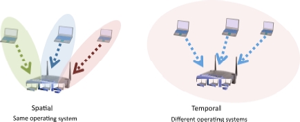
Figure 6.13. Virtualization of 5G devices
The virtualization of an HNB (Home NodeB) or an MNB (Metro NodeB) is illustrated in Figure 6.14: the box has a hypervisor which supports virtual HNBs. Each HNB or MNB uses its own technology, provided it is compatible with the common antenna and the resources of the node. In the case of a domicile or a shared property, this solution can be used to share a box between several operators. Additionally, each operator can perfectly well manage multiple software networks in the same box for different applications. The Achilles’ heel of this technology is the antenna’s capacity, which is shared between the different clients. The advent of 11ac, 11ad, 11af and 11ah technology should facilitate the introduction of these new devices, thanks to very high data rates. With virtualization, each user is given the illusion of having the desired capacity all to him/herself.

Figure 6.14. Virtualization of an HNB
Virtualization is found in various types of 5G networks, such as mesh networks. This scenario is illustrated in Figure 6.15. The machines which manage the mesh network have two interfaces: one interface with the users and the other with the other machines in that mesh network. These machines are virtualized with a hypervisor which supports mesh routers or switches, depending on the technology employed – e.g. using a TRILL protocol. It is possible for the machines to communicate by using Ethernet routing. Of course, there are IP routing possibilities which have been greatly developed by the MANET group at the IETF. One of the advantages of this solution is that certain networks can be allocated greater resources than they could have had if there had only been one network.

Figure 6.15. Virtualization of a mesh access network. For a color version of the figure, see www.iste.co.uk/pujolle/software.zip
Look at the example of a VoIP network (Voice over IP): the software network assigned to it may contain far more resources than are actually needed by the VoIP flows. As the networks are isolated, the VoIP network is sure to receive at least the amount of resources that it really needs in order to deliver the desired level of QoS. Any resources which have not been used will be reallocated to other networks. Thus, we can determine a hierarchy of priority, in the knowledge that the network with least priority will have at least the resources assigned to it when the resources are apportioned to each network.
We can do exactly the same thing for the backhaul networks, which link the access networks to the core network. By virtualizing the backhaul network, we are able to deliver quality of service to the virtual networks which need it. In addition, if the access networks are virtualized, the backhaul networks must be virtualized as well, so that the classes of service are compatible. Figure 6.16 shows a backhaul network which can be virtualized by nodes supporting hypervisors and hosting appropriate virtual machines.

Figure 6.16. Virtualization of a backhaul network
6.15. C-RAN
C-RAN, or Cloud-Radio Access Network, is a system put forward in 2010 by China Telecom, with the aim of profoundly changing the access and backhaul networks between the core network and the peripheral devices. To begin with, the architecture is based on the Cloud: all the control algorithms are handled by datacenters. This architectural arrangement could have been reached simply by continuing to use the conventional access networks connecting clients to the Nodes-B. Nonetheless, the proposition is fairly revolutionary, in that the access network is eliminated completely, and replaced with a very simple solution whereby the radio signal is sent directly to the datacenter. The radio signal is transferred to the Cloud as it is, without being embedded in a packet. The signal processing takes place in the Cloud. The original idea of C-Cloud is shown in Figure 6.17. The terminals are connected to the antennas, which re-transmit the signal to the central cloud, where it is computed. Once it is received by the antenna, the signal is sent back over an optical fiber, using a technique known as RoF (Radio over Fiber). The major advantage of RoF technology is that the same antenna can be used to handle very different signals, such as 3G, 4G, 5G or Wi-Fi. It is the Cloud which unscrambles the signals and determines their characteristics in order to be able to decode.

Figure 6.17. The fully-centralized Cloud-RAN architecture
We can also cite other advantages, such as the low attenuation of the signal over the fiber, so the datacenter can be far away from the source. The cost of connection is also going down, thanks to multiplexing on the same antenna, but also on the same optical fiber. The complexity of the access network is eliminated, and the datacenter handles this complexity with appropriate virtual machines. This technology is found in the cabling solutions used at certain large stadia or shopping centers.
The main disadvantage stems from the use of FTTA (Fiber to the Antenna) which is necessary for the communication. If the building containing the Wi-Fi access points is not cabled, then installing an optical cable can often be extremely costly. The optical fiber is connected to the datacenter by a BBU (BaseBand Unit) and, on the other end, is connected to the physical antenna by an RRH (Remote Radio Head).
The standardization currently under way for NFV (Network Function Virtualization) includes C-RAN. Functions in the NFV environment are defined to decouple the work carried out on the node, which was previously done by the antenna, and move it to a datacenter.
Whilst the C-RAN architecture is an interesting option for countries wishing to develop a new infrastructure, it is much less attractive to countries which already have a local-loop infrastructure for RAN. In such cases, the proposition is to keep the existing structure and add Cloudlets near to the antennas to perform computation locally. The computation pertains to the signal but also to the signaling, with algorithms to manage handover or the choice of connection to be favored when multiple options are available. This architecture is illustrated in Figure 6.18.

Figure 6.18. The partially-distributed Cloud-RAN architecture
6.16. The Internet of Things
The Internet of Things was born with the idea of connecting wireless and hardwired sensors, found in the home, at work and more or less everywhere in life today, to the Internet. One of the most widely used sensors is RFID (Radio-Frequency Identification), or electronic tags. The Internet of Things enables us to connect anything and everything that is connectable, from varied objects to smart dust. The concept is simple, but the problems are numerous, because in general, the “things” in question are not sufficiently sophisticated to handle the communications and computations associated with the applications.
We shall begin by examining sensor networks, followed by RFID networks and the NFC (Near-Field Communication) interface – which is increasingly being used in the connection of “things” to the Internet – and HIP (Host Identity Protocol), which could become the standard for interconnection gateways between “things” and the Internet. Finally, we shall touch on a few ideas about one of the most rapidly developing types of networks: medical sensor networks, which could potentially affect seven billion people, and constitute a truly enormous potential market.
6.17. Sensor networks
A sensor network is defined as a set of interconnected sensors, with each sensor having a transmitter-receiver. Sensor networks form a new generation of networks with specific properties, which do not fit into the framework of conventional architectures. However, the dawn of the Internet of Things has altered our view of sensor networks, which may, of course, still constitute a closed system, but also connect to the Internet.
The miniaturization of the sensors poses problems in terms of communication and energy resources. The sensor needs to be sufficiently intelligent to gather the required information and transmit it correctly. In addition, the sensor’s processor must not be used too intensively, so as to consume as little energy as possible. Thus, it must incorporate reactive elements, rather than cognitive ones. Finally, in order to ensure a good data rate, the range of the transmitter-receivers must necessarily be small – around ten meters. Therefore, the establishment of a sensor network poses problems of routing, error control and power management.
Very special sensors are involved in what we call “smart dust”. These dust particles, which are practically invisible, have a radio device in addition to performing the computations relating to the internal sensor.
From the standpoint of communication, the environment of IP is too intensive, leading to an excessive data rate and overconsumption. Solutions derived from terrestrial networks, or industrial real-time networks, offer a better compromise between efficiency and power consumed. As there may be hundreds of such sensors per square meter, IPv6 routing represents one obvious solution to deal with the problem of addresses. However, the IP environment is cumbersome, and it is often impossible, in these sensor networks, to use a TCP/IP or even UDP/IP protocol stack.
For the moment, security and QoS problems are taking a back seat to energy consumption problems. In any case, a great deal of research is currently being done to render sensor networks efficient and robust.
The main radio standards are ZigBee, WiBree and 6LowPAN. WiBree is a very low-consumption technology with a range of 10 m and a data rate of 1 Mbps. This solution was developed by Nokia to compete with both ZigBee and Bluetooth. However, it was integrated with Bluetooth in 2009, with the resulting product being called Bluetooth LE (Low Energy).
6LowPAN networks (IPv6 over Low power Wireless Personal Area Networks) were proposed by a working group at the IETF. The objective, obviously, is to facilitate continuity of IP on non-powerful machines with limited electrical power.
The use of the IPv6 standard to obtain a very large number of addresses for immense sensor networks poses a problem. The 16 bytes occupied by the transmitter’s address, added to the 16 bytes of the receiver address, plus the obligatory fields, lead to poor usage of the radio link to transport the supervision data. This could become genuinely problematic in light of how little energy the sensor has. ZigBee, on the other hand, limits the length of its frame to 127 bytes, which may also cause problems if the message supplied by a sensor for transmission is long.
Sensors form ad hoc networks, and they need a routing protocol. The use of a protocol such as IEEE 802.11s, in combination with IPv6 addresses, would be catastrophic for the sensors’ battery life. For this reason, current propositions are much simpler, with protocols such as LOAD (6LowPAN Ad hoc On-Demand Distance Vector Routing Protocol), a simplified version of AODV, DyMO-Low (Dynamic MANET On-demand for 6LowPAN), a simplification of DyMO, from the MANET working group, and Hi-Low (Hierarchical Routing over 6LowPAN). These different protocols stem from propositions by the IETF, and therefore the standardization of ad hoc networks, but they do not include all the potential options.
Another important characteristic of the protocols used in sensor networks is service discovery, which should enable the automatic establishment of a connection. The IETF also plays an important role in this domain, having published several proposed solutions – one of which is sensor-oriented: LowPAN Neighbor Discovery Extension. This protocol is a reduction of the Neighbor Discovery standard, which pertains to all energy-consuming elements, including broadcasts and multicast management.
A very special example of a sensor network is offered by smart dust, the aim of which is to develop nanotechnology sensors and to connect them to one another by an ad hoc network. Smart dust fits into a space smaller than a cubic millimeter – hence the name. Each grain of this dust contains the components necessary to constitute a communicative computer: a processor, memory, radio, battery, etc.
Here, the main problem is the saving of energy while performing sensor functions. In particular, the network part must carry out communications using very little energy indeed. Thus, Berkeley University has designed a specific operating system and protocols, known as TinyOS and Tiny protocol. TinyOS is written in simplified C language, called nesC, which is a sort of dialect designed to optimize memory usage.
6.18. RFID
RFID (Radio-Frequency Identification), or radio-identification, was introduced for the purpose of identifying objects, so it is also known as electronic tagging.
Electronic tags are scanned by a reader, which is able to recover the identification data. The tags are used in numerous applications, from the tracking of animals to security tags in stores.
There are two main types of electronic tags: passive and active tags. Passive tags have no energy source. They are activated by a reader which supplies a sufficiently strong electromagnetic field to generate an electrical current, facilitating the radio-wave transmission of the binary elements stored in an EEPROM memory, constituting the RFID identification. A passive tag is illustrated in Figure 6.19. The antenna must be built in such a way as to be able to receive the electromagnetic field from the reader and transmit its identity.

Figure 6.19. An RFID
A passive RFID may be very small. As the equipment requirements are limited, sizes of around a tenth of a millimeter are sufficient. The price of an electronic tag depends on the number of elements manufactured in one batch. It is possible to go as low as 5 euro cents.
Active electronic tags have a source of electrical supply within the component. The first, extremely significant, advantage of such tags is the quality of the transmission. A session can be established between the reader and the RFID so that the signal is automatically retransmitted in case of a problem. Another advantage is transmission with a range of several meters between the RFID and the reader, instead of only a few centimeters. One disadvantage could be the battery life. However, with typical usage of a few readings per day, it is possible to achieve battery life of over ten years.
The active RFID may have a larger memory for storing attributes associated with the value of the ID.
An active RFID is shown in Figure 6.20.

Figure 6.20. Active RFID
One very well-known application of RFIDs is the electronic passport. The e-passport is defined in a text published by the ICAO (International Civil Aviation Organization). The chip in the e-passport contains the same data that are printed on the passport itself, along with a digitized photo of the passport holder.
Transport documentation (tickets, etc.) is a second application for RFIDs. For example, the tickets sold on the Paris Metro contain an electronic tag which memorizes a set of data including the date and place of purchase. More sophisticated solutions are used on public transport in Seoul, where the tag is active and contains money, so that the same ticket can be used multiple times.
Toll barriers on the roads also use this active RFID solution, with ranges of a few meters. The active tag is able to subtract the cost of the toll from the amount of money stored in the memory. Similarly, toll barriers for the ski lifts in many resorts in France use active RFIDs.
Another fairly immediate application is the tracking of cars, to detect stolen cars when they pass near a RFID reader.
Finally, two of the best-known applications of RFID are for inventory and for purchases in stores. Inventories can be taken more often, and with fewer errors. Similarly, items put into a shopping cart can be recorded by the reader, which greatly simplifies the process of payment for those items in a shop.
RFID transmission frequencies are determined by local or regional standardization bodies. The main ones are indicated in the following table:
| Frequency for RFID | Comment |
| 125KHz(LF) | First solution to offer a relatively large range for passive RFIDs |
| 13.56MHz (HF) | One of the standardized frequencies very widely used for passive RFIDs |
| 400 MHz | A number of specific uses, such as the detection of stolen vehicles |
| 865-868MHz(UHF) | Frequency band standardized in Europe for intensive RFID use |
| 902-928MHz(UHF) | Frequency band standardized for North America |
| 2.4-2.4835GHZ | SM open band in which numerous RFID applications are likely to develop |
6.19. EPCglobal
The purpose of RFIDs is to give the identity of the objects to which they are attached. This identification system has been standardized by the consortium EPCglobal. Two generations are available: EPC Gen1 and EPC Gen2. We shall focus particularly on this second generation, released in mid-2006, which has become an industrial standard.
EPC Gen2 is the acronym for “EPCglobal UHF Class1 Generation 2”. Version 1.1 of this specification was released in May 2006. It handles the protocol between the reader, on the one hand, and the RFID and the identity, on the other. The object of the protocol is to read, write and eliminate an RFID, so that readers sold by all manufacturers are interchangeable.
The reading procedure is defined using a timeslot-based system with an anti-collision system. Specifically, a reader can simultaneously trigger a large number of RFIDs, but the simultaneous reading of different tags would lead to collisions. Signaling is used to determine the frequency, the coding used (between DSB-ASK, SSB-ASK and PR-ASK) and the data rate of the channel. The anti-collision system means that, whenever tags are read simultaneously, only half of the objects that have been able to transmit are allowed to transmit again the next time. After a certain number of collisions, only one RFID is able to successfully transmit. The algorithm is designed in such a way that each RFID then takes turns to transmit. The reading speed may be up to 640 Kbps.
The identity of the object is determined by the EPCglobal Electronic Product Code. Gen1 uses 96 bits, whilst in Gen2 the code is 256 bits in length. An example of this ID for Gen1 is illustrated in Figure 6.21. Figure 6.22 shows the ID fields in Gen2. This solution is much more complex, because it uses intermediary filters to determine the lengths of the subsequent fields. Note that the serial number grows from 36 to 140 bits, which means that, for a given article, the value never has to return to 0.

Figure 6.21. Structure of GEN1 Electronic Product Code

Figure 6.22. The structure of GEN2 Electronic Product Code
6.20. Security of RFID
Security is a thorny issue in the world of RFID. Indeed, a passive RFID device can be easily read by a third-party reader. In addition, individuals’ privacy may be violated by monitoring and tracing of everything relating to those individuals.
There are solutions available, such as encoding the ID in the tag or changing the value of the tag every time it is read. These solutions rely on middleware which is able to interpret the values of the tags or keep track of the changing values.
Active tags can establish an authentication session, facilitating an exchange with the reader, which then acts as an authentication server. In this case, we need to use an electronic circuit in the tag, capable of encrypting a text transmitted by the authentication server. However, the encryption keys used are so short that there is a not-insignificant danger of them being broken after a series of authentication attempts. Numerous propositions have been made, using the anti-collision algorithm, which serializes the reading of the tags, for authentication.
6.21. Mifare
Mifare is the most widely-used of contactless cards, with four billion in circulation throughout the world. The name comes from the company with developed it – Mikron; the full name of the card is “Mikron FARE”. Mikron was bought out by Philips, which ceded ownership of this technology to its subsidiary: NXP. There are two different sub-types of Mifare cards: Mifare Classic, which uses only a certain portion of the Mifare command set, and Mifare from NXP, which implements the entire range of commands.
The cards communicate with a reader, which must be at a distance of less than 3 centimeters. This provides a certain amount of security for the communication, which is highly localized. However, attacks have been carried out, using very specific readers placed a few meters away. If we require security in a communication, the best thing to do is to encrypt the data for transmission.
These cards are not very powerful at all, so their production costs are extremely low. Mifare Classic cards have a 4- or 7-byte serial number and a storage memory between 512 bytes and 4 Kbytes. The cheapest version is the Mifare Ultralight, which usually serves as a disposable ticket.
Mifare T=CL cards use secure elements of the same type as contact chip cards, and essentially provide the same type of service.
The most highly developed card is Mifare DESfire, which has a larger memory and an advanced operating system, as well as AES and 3DES encryption protocols.
Mifare cards serve numerous applications. The most common include: the reading of a serial number, to trigger a particular action if that number is accepted by the reader; the reading of an ID memorized on the card; or data storage. For the first application, we use the card’s serial number, which is encoded on 4 or 7 bytes. In the second case, the ID must be entered into the card, which may encrypt it, provided it has a secure element capable of carrying out cryptographic computations.
6.22. NFC (Near-Field Comunication)
The NFC standard is a special case of RFID communications. It facilitates communication between an RFID and a reader over a distance of up to ten centimeters. This is contactless communication, with, for instance, a chip card or a secure microcontroller.
There are numerous and varied applications of this type. The best known is payment over a mobile phone. With his/her mobile, a client can top up his/her account with a simple phone call or low-data-rate data transfer to a server. Once the account is topped up, the mobile serves as a key to pay for a whole range of services. For example, to buy a subway ticket, we need only hold the mobile near the reader for radio communication to validate the purchase of the ticket.
NFC data rates are fairly low: 106, 212, 424 and 848 Kbps. The frequency range is around 13.56 MHz. The standards in this field were issued by the ISO/IEC. The NFC Forum was set up by Philips and Sony.
The security of the communication is assured because of the very short distance between the transmitter and the receiver and the presence of the chip card. Nevertheless, in spite of the maximum distance of 3 centimeters, in 2012, attempts were made to spy on NFC remotely. Therefore, it is advisable to encrypt the communication.
We shall now look at an example of the use of NFC, with mobile keys.
6.23. Mobile keys
Car keys, house keys or hotel keys could soon be included in smartphones. One of the advantages of mobile keys is that they can quite easily be transmitted to a friend waiting outside your door, or sent to customers by car rental companies. We shall describe the way in which this application works by taking the example of opening a hotel door with a smartphone.
Mobile keys are stored in a secure server or in a datacenter in a Cloud. The client has a smartphone, containing a secure zone to store the key. The door to the room has an NFC lock. The environment of this example is illustrated in Figure 6.23.

Figure 6.23. The environment of a mobile key
To begin with, the room is reserved using the mobile terminal. The smartphone must contain a secure element, i.e. a placement which cannot easily be reached from outside. This secure element may be a variety of different types, depending on the terminal (smartphone, tablet, laptop, etc.). It could be a SIM card from the operator, but in this case we also need the operator’s authorization to use it. It may also be a so-called “embedded SIM”, which is the equivalent of a chip card, but inserted by the manufacturer that made the smartphone. Most of the time, it is an NXP component which possesses much more than 50% of the market. It may also be a memory card (SD card) which is embedded in the mobile phone. Finally, as indicated in Figure 6.23, it may be an intermediary chip card (a loyalty card from the hotel where the client wishes to stay) that communicates with the mobile through the NFC interface. The mobile, in this case, is seen as a modem which facilitates communication between the external chip card and the key server. The key server is hosted in the Cloud. The door itself is NFC, and can be opened by a digital mobile key situated on the smartphone or on the external NFC card.
When the client arrives in the vicinity of the hotel, it is detected by the smartphone’s GPS. The phone then transfers the key to the room into the secure zone of its security apparatus or directly to the external NFC chip card. We then merely need to bring the smartphone or the external card near to the NFC interface of the card to open the door.
6.24. NFC contactless payment
At the start of 2014, the number of contactless bank cards was 20% of the total number of bank cards. Similarly, 20% of smartphones had an NFC chip. Before the dawn of NFC, other payment systems had been tried, such as SMS payment, a direct-payment model and a solution using WAP. Over the past few years, payment using NFC cards has expanded hugely, and numerous variants have been defined.
In the context of NFC, the mobile must be brought to within a few centimeters of the payment terminal. Two major axes for this have been established: prepayment and direct payment. In the first case, the terminal is seen as an electronic wallet: with each transaction, money is taken from the wallet. The payment for a very small maximum sum can be assimilated to this first axis. The second case requires more security, because payment is taken directly from the user’s account, with the sums involved generally being much higher.
There are four possible models of mobile payment:
- – Operator-Centric Model: the mobile operator alone deploys the mobile payment services. To do so, it needs to provide a mobile wallet that is independent of the user’s account. This scenario is pretty rare, because the operators are not linked to the major international payment networks. The mobile network operator must manage the interface with the bank network in order to be able to provide advanced mobile payment services. Pilots using this model have been launched in developing countries, but they offer only very partial coverage of the numerous use cases of mobile payment services. In general, the payments are limited to transfers or to modest sums;
- – Bank-Centric Model: the bank runs mobile-payment applications associated with client machines, and asks retailers to have the necessary equipment to effect the sales. The mobile network operators are responsible for the transport network, with the quality of service and the security needed for the payment functions;
- – Collaboration Model: this model involves a collaboration between the banks, the mobile operators and a trusted third party;
- – Peer-to-Peer Model: the mobile payment service provider acts independently of the financial institutions and of the mobile network operators.
Google, PayPal, GlobalPay and GoPago use a Cloud-based approach to make mobile payments. This approach places the mobile payment provider at the heart of the operation, which involves two distinct steps. First of all, a payment method associated with the Cloud is selected, and the payment is authorized via NFC. At this step, the payment provider automatically covers the cost of the purchase. In the second step, another transaction is necessary: the user’s bank must reimburse the payment provider for that payment and any fees associated therewith.
6.25. HIP (Host Identity Protocol)
The IETF has developed various mechanisms to integrate things with the Internet. HIP is an identification technology which is part of this set of measures. This protocol is standardized by the IETF in RFC 4423 and the series RFC 5201 to 5207.
In the world of IP, there are two main naming conventions: IP addresses and the domain-name system. The purpose of HIP is to separate the endpoint ID and the localization of IP addresses. This approach is of the same type as LISP, described in Chapter 4.
For this purpose, HIP introduces a namespace based on a PKI infrastructure. This space enables us to manage multihoming securely. The IP addresses are replaced by encoded Host Identities (HIs).
6.26. The Internet of Things in the medical domain
The use of the Internet in the medical domain is on the rise, with 7 billion people to monitor, diagnose and care for. The long-term idea is to be able to continuously monitor individuals with a view to advising them or alerting them to any problems detected. A priori, in the future, everybody will be able to have uninterrupted connection to a Cloud, which will analyze the data provided by sensors both inside the body and on the surface. The power of the Cloud will be such that we will be able to analyze, compare and make diagnoses on the basis of this stored dataset. Essential characteristics in this field are security, “privacy” – i.e. the private nature of the data – and the very low energy consumption of the sensors, which must be able to operate for months on end with no need to change the batteries. This environment is being established bit by bit, and we shall now go on to describe the main advances from the networking standpoint.
The first element that we shall discuss is the sensor network adapted for use with the human body, called a BAN (Body Area Network). An example of a BAN is shown in Figure 6.24.

Figure 6.24. A BAN (Body Area Network)
It is the working group IEEE 802.15.6 which takes care of its standardization. The main standards issued by this working group cover multiple frequencies and multiple technologies:
- – 402-405MHz for In-In-Out communications – i.e. inside the body and from the inside to the surface of the body;
- – Ultra Wideband (UWB), which operates on the 2.4 GHz and 3.1-10.6 GHz bands;
- – between 15 and 50 MHz for communications inside the body;
- – HBC (Human Body Communications), which operates at 13.5, 400, 600 and 900 MHz for communications on the surface of the body. This communication uses the electrical conductivity of the human body. The intensity of the electrical current, therefore, is extremely low – around a nano-ampere.
To interconnect BAN networks with the Cloud, a number of solutions are envisaged: using the LTE network, or 4G, or a new generation of Wi-Fi network. In the United States, the FCC is working to develop a specific band for medical Wi-Fi, with much stricter security standards than those in force in Wi-Fi today. The bandwidth is 40 MHz, with a very low-consumption technology. The band for such external connections would be between 2360 and 2400 MHz – i.e. just below the current Wi-Fi band.
Other research, which is progressing well, regards the use of integrated sensors in “smart dust” capable of circulating in the blood. Analyses are regularly transmitted to external sensors which, in turn, transmit to the Cloud.
6.27. The Internet of Things in the home
The home is a place where we find a large number of very diverse sensors from different domains: ICT, telecommunications, medicine and electronics. For instance, we find Internet beds which have sensors that are able to detect all movements and speech during the night to aid in the diagnosis of sleep problems. Doors, household appliances, lightbulbs, security systems, etc., are, themselves, filled with increasing numbers of varied sensors. Another example is given by presence sensors, which detect whether or not a person is in a room, with a view to automatically turning the lights on or off. Overall, we expect to find around 100 sensors in every home by around 2020.
There is a major struggle going on between household appliance manufacturers, to determine which type of connection technology all those sensors will use in the home. The base network uses Ethernet, cable or Wi-Fi. Hence, most devices can be connected directly using an Ethernet port or a Wi-Fi card. Bluetooth, 6 LowPAN, ZigBee and NFC are also in the running. A communications controller should be able to personalize all the connections and ensure they have adequate security, good availability, reasonable energy consumption and as low a cost as possible.
The issue stems from the new generation of Home Gateway, which raises the question of management of IP in the terminal machine. For television sets, telephones and other fairly important machines, the presence of an IP component poses no problem: this is what we find in IPTV or IP telephony. On the other hand, for a very cheap sensor or device, it is either impossible or too costly to introduce an IP component and have an intermediary machine such as a controller. The controller can also be integrated into the Home Gateway. HIP, described a little earlier, can be used to perform communications, firstly with the sensor, and secondly with the Home Gateway.
In conclusion, the home contains a large number of “things” which it is possible to connect. Therefore, the Home Gateway is of prime importance, as it allows us – perhaps with a controller – to manage not only the communications, but also the security and quality of service of the “things” in the home.
6.28. Conclusion
5G is an environment that brings together numerous networks with different architectures and different protocols. This combination of technologies to form 5G is made possible by the arrival of the Cloud, Cloudlets, SDN (Software-Defined Networking) and SDR (Software-Defined Radio). Its design ranges from D2D-type solutions to the connection of billions of more or less intelligent things. Virtualization plays an important role because, almost everywhere, there is a decoupling between the physical device and the control device, which is usually situated in a datacenter specialized for the application.
The Internet of Things is becoming a reality thanks to RFID and sensors. However, we are still a long way from being able to completely integrate all these small devices, because they are not powerful enough to support TCP/IP, and yet they are rather energy-hungry. In order to achieve this goal, we need to use very specific gateways, which can include the connected things on the one hand, and the Internet on the other. HIP could become the fundamental standard of this connection solution.