5 DC Motors
DC motors convert electrical energy into mechanical energy and have construction very similar to that of a DC generator. Generators are operated in protected locations. Therefore, their construction is usually of the open type. Since DC motors do not operate in protected locations, they face dust, moisture, fumes and tend to get mechanical damage. Hence, their construction is of closed type. The operation of motors is based on the principle – when a current-carrying conductor is placed in a magnetic field, it experiences a mechanical force. The magnitude of this force is F = BIL, and its direction is determined by Fleming's left-hand rule. The aim of this chapter is to discuss DC motors in detail.
5.1 VOLTAGE EQUATION
DC motors are of shunt type, series type and compound type. They are similar to their DC generator counterparts. The difference is that the prime mover is absent and DC supply is given from supply mains to the terminals of the motor. The shunt motor and series motor are shown in Figures 5.1(a) and 5.1(b), respectively.
In Figure 5.1, let
| Vt | be the supply voltage, |
| Ra | be the armature resistance, |
| Eb | be the back emf, |
| I | be the current drawn by the motor from supply mains, |
| Ia | be the armature current, |
| Ish | be the shunt fi eld current – Figures 5.1(a), |
| Ise | be the series fi eld current – Figures 5.1(b), |
| Rsh | be the shunt fi eld resistance – Figures 5.1(a) and |
| Rse | be the series fi eld resistance – Figures 5.1(b). |
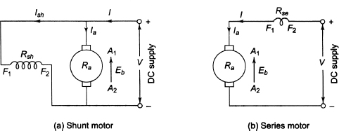
Figure 5.1 DC Motors
The supply voltage (Vt) of the motor overcomes the following:
(i) the back emf (Eb) and
(ii) the armature ohmic drop (or, IaRa drop.)
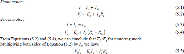
In Equation (5.5),
VtIa is the electrical power input,
EbIa is the gross mechanical power developed in the armature denoted by Pm and
Ia2Ra is the armature Cu loss.
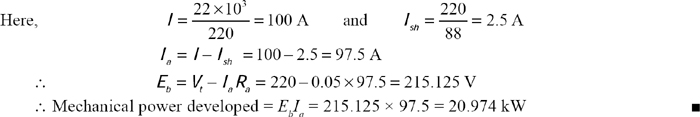
Example 5.1 The field and armature resistances of a 220 V DC shunt machine are 88Ω and 0.05Ω respectively. Calculate the total armature power developed when working
(i) as a generator delivering power of 22 kW and
(ii) as a motor taking 22 kW input.
Solution
- Generator:
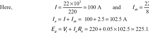
 Power developed in armature = EgIa = 225.125 × 102.5 = 23.075 kW
 - Motor:
5.2 BACK EMF
During rotation of the armature, its conductors cut the magnetic flux and emf is induced in the conductors according to the laws of electromagnetic induction. The direction of this induced emf can be found by Fleming's right-hand rule and have the direction opposite to the applied voltage. Therefore, this induced emf is called back emf (Eb) having the following expression:
![]()
5.3 CONDITION FOR MAXIMUM MECHANICAL POWER
Differentiating Equation (5.7) with respect to Ia,
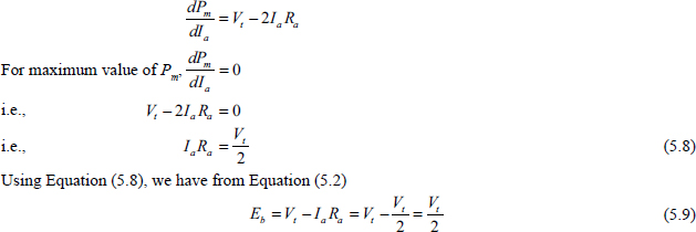
The back emf is equal to half of the applied voltage for maximum gross mechanical power. It is impossible to achieve this condition practically. Since half of the power input is wasted as heat in the armature, efficiency will be less than 50 per cent taking account of other mechanical losses also.
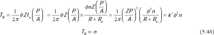
5.4 ARMATURE TORQUE OF A MOTOR
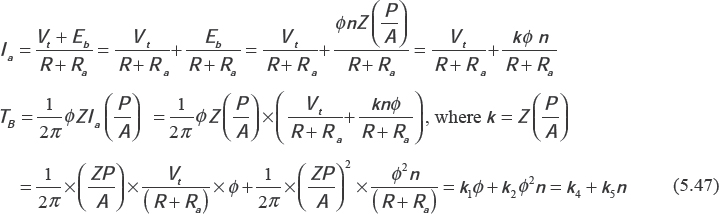
If Ta be the gross torque developed by the armature rotating at a speed n rps, the mechanical power (Pm) developed is expressed as follows:
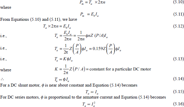
If speed (N) is in rpm, the torque is expressed by
![]()
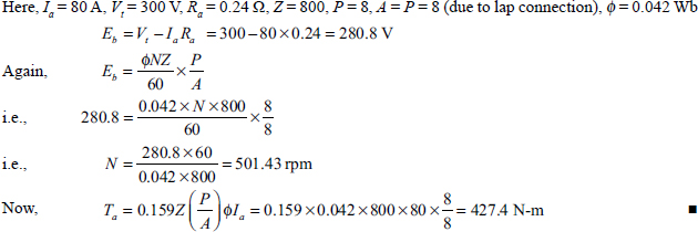
Example 5.2 A DC shunt motor having armature resistance of 0.24 Ω takes an armature current of 80 A at 300 V. The machine has eight poles and 800 lap-connected conductors. The flux per pole is 0.042 Wb. Calculate the speed and gross torque developed by the armature.
Solution
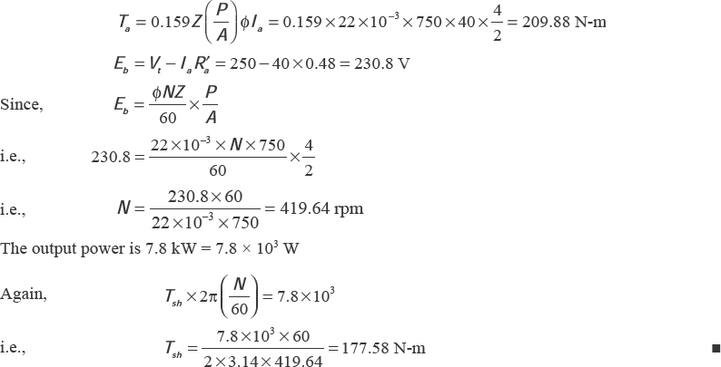
Example 5.3 A four–pole, 250 V, wave–connected DC series motor with 750 armature conductors supplies a load of 7.8 kW and takes a current of 40 A from the supply mains. The flux per pole is 22 mWb and the sum of armature and field resistance is 0.48Ω. Calculate the developed torque and shaft torque.
Solution
Here, Ia = 40 A, Vb = 250 V, R′a = Ra + Rse = 0.48 Ω, Z = 750, P = 4, A = 2 (wave connected), φ = 22 mWb Developed torque and gross torque are nothing but armature torque.
5.5 ROTATIONAL LOSSES OF DC MACHINES
DC motors have the following rotational losses:
(i) loss due to friction of bearings,
(ii) the windage loss due to consumption of power by the circulation of air or other cooling gas in the machine and
(iii) losses in the magnetic core of the machine known as core losses or iron losses. Core losses are divided into hysteresis loss and eddy current loss.
Let Pr be the rotational loss, Pb be bearing friction loss, Pw be windage loss, Ph be hysteresis loss, Pe be eddy current loss and Pi be iron or core loss = Ph + Pe.
![]()
Let Ta be average torque or internal torque at which the conversion of electromechanical power takes place, Tsh be useful torque or shaft torque developed at the shaft of an electric motor and TP be prime mover torque applied at the shaft of a generator.
For a DC generator, we have
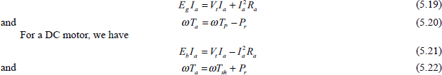
Equations (5.21) and (5.22) are known as the power equation for a DC generator and a DC motor, respectively. Ta is called the armature or gross torque and Tsh is called the useful torque, shaft torque or net torque.
From Equation (5.22), we have
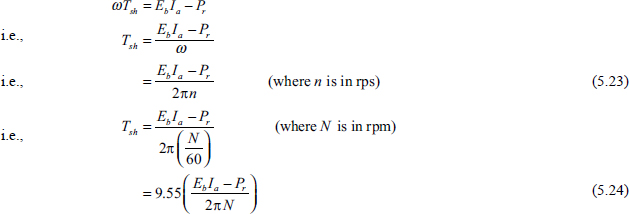
Example 5.4 A DC series motor rotates at 1,000 rpm and draws 50 A at 250 V. Its armature and field resistances are 0.22Ω and 0.12Ω, respectively. The iron and friction losses are 0.54 kW. Find the developed torque and output power of the motor.
Solution
Here, Vt = 250 V, I= 50 A, Ra = 0.22Ω, Rse = 0.12Ω, N = 1000 rpm and iron and friction losses = 0.54kW = 540 W
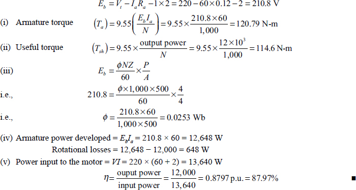
Example 5.5 A four-pole, 220 V, lap-connected DC shunt motor delivers 12 kW. It runs at a speed of 1,000 rpm and draws armature and field current of 60 A and 2 A, respectively. The total number of armature conductors is 500 and armature resistance is 0.12 Ω. Calculate (i) total torque, (ii) useful torque, (iii) useful flux/pole, (iv) rotational losses and (v) efficiency. Assume 1 V per brush for contact drop.
Solution
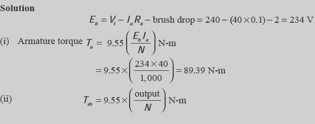
Example 5.6 A four-pole, 240 V, wave-connected DC shunt motor gives 9 kW when running at 1,000 rpm and drawing armature and field currents of 40 A and 1.0 A, respectively. It has 500 conductors and armature resistance of 0.1Ω. Assuming contact drop of 1 V per brush, find (i) total torque, (ii) useful torque, (iii) useful flux/pole, (iv) rotational losses and (v) efficiency.
Solution
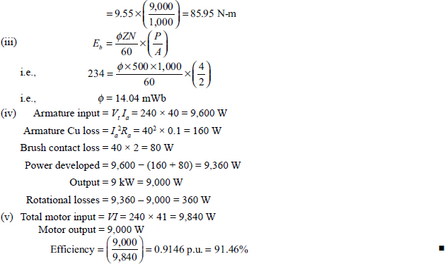
Example 5.7 A DC series motor running at 2,000 rpm has the hysteresis and eddy current losses 500 W and 200 W, respectively. If flux remains constant, calculate the speed at which total iron losses are halved.
Solution
Hysteresis loss = C × 2,000 = 500 W
Eddy current loss = D × 2,0002 = 200 W
5.6 COMPOUND MOTOR
Compound motors have both series and shunt windings, and they may be short shunt type or long shunt type depending upon the connection to the field windings. Depending on whether the series field aids or opposes the shunt field, this machine is said to be a cumulatively compounded or differentially compounded DC machine.
5.7 RELATION OF SPEED (N) WITH BACK EMF (Eb) AND FLUX (Φ)
From Equation (5.6), we have
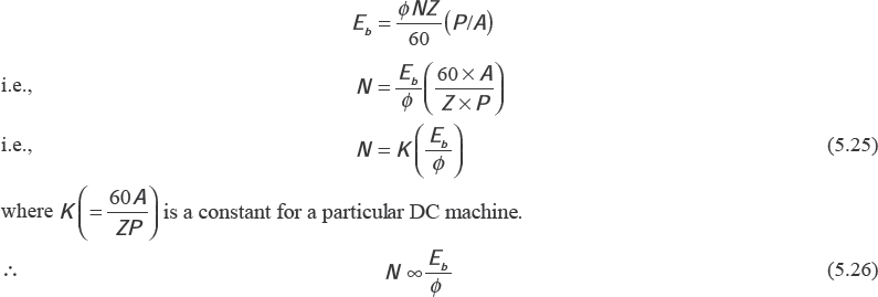
From Equation (5.26), we conclude that speed (N) is proportional to the back emf (Eb) and it is inversely proportional to the flux (φ).
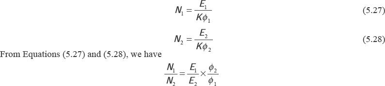
If N1 (in rpm) and N2 (in rpm) be the two different speeds of a DC machine corresponding to the flux φ1 and φ2, respectively, we have
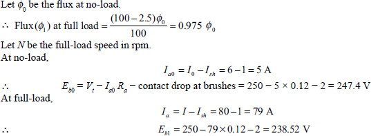
Example 5.8 The no-load current and speed of a four-pole, 250 V, DC shunt motor are 6 A and 500 rpm, respectively. It has a shunt field current of 1 A. If its full-load current is 80 A, find its full-load speed. The value of armature resistance is 0.12Ω. Consider 1 V per brush for contact drop. Armature reaction weakens the flux by 2.5 percent.
Solution
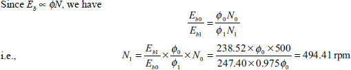
![]() The full–load speed of the motor is 494.41 rpm.
The full–load speed of the motor is 494.41 rpm.
5.8 CHARACTERISTICS OF SHUNT OR SEPARATELY EXCITED DC MOTOR
For shunt and separately excited DC motors, the field winding is supplied from a constant voltage. So the field flux remains constant. Thus, the shunt and separately excited DC machine have the same characteristic. Using Equation (5.2), Equation (5.26) can be written as follows:
![]()
Since Φ is constant for a DC shunt motor, we have
![]()
Since Ra is very small, IaRa is also small.
The torque of any DC shunt motor is expressed by Equation (5.15).
The speed versus armature current and torque versus armature current are shown in Figures 5.2(a) and 5.2(b), respectively.
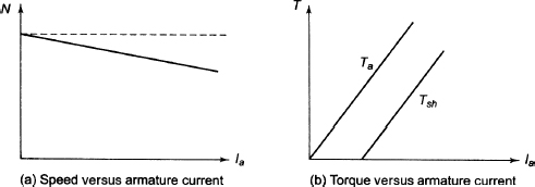
Figure 5.2 Characteristics of a Shunt or Separately Excited DC Motor
Let Tg be the gross torque and Tsh be the useful torque or shaft torque.
![]()
where Tf is frictional torque and Tw is windage torque.
5.9 CHARACTERISTICS OF DC SERIES MOTOR
Using Equation (5.4), Equation (5.26) can be expressed as follows:
![]()
Equation (5.31) shows the expression for the speed of a DC series motor.
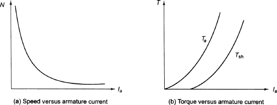
Figure 5.3 Characteristics of a DC Series Motor
At low value of Ia, Ia (Ra + Rse) can be neglected compared to Vt. Equation (5.31) reduces to
![]()
Since supply voltage Vt is constant,
![]()
In a series motor, flux (Φ) is proportional to the armature current (Ia). Therefore, we have
![]()
Using Equation (5.34), Equation (5.33) can be expressed as follows:
![]()
The torque of a DC series motor is expressed by Equation (5.16).
The speed (N) versus armature current (Ia) and torque (T) versus armature current (Ia) are shown in Figures 5.3(a) and 5.3(b), respectively.
5.10 CHARACTERISTICS OF COMPOUND MOTOR
Speed (N) versus armature current (Ia) and torque (T) versus armature current (Ia) are shown in Figures 5.4(a) and 5.4(b), respectively.
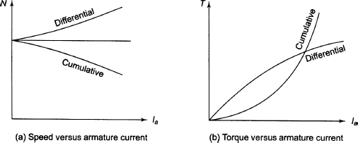
Figure 5.4 Characteristics of DC Compound Motor
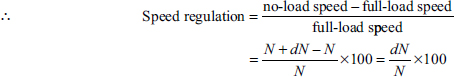
5.11 SPEED REGULATION
The change in speed of a motor, with change in applied torque while other condition remains unaltered, is known as speed regulation. The change in speed occurs due to inherent properties of the motor itself and not by manipulation of rheostats or other speed controlling devices. The change in speed when the load on the motor is reduced to zero from full-load is known as speed regulation, and it is expressed by the percentage of the rated load speed.
5.12 TORQUE AND SPEED OF DC SERIES MOTOR
Using Equation (5.20), Equation (5.25) can be expressed as follows:
![]()
From Equation (5.14), the expression for the torque is rewritten:
![]()
From Equations (5.36) and (5.37), we can observe that increase in the value of Φ will decrease N and increase T, which are contradictory to each other. The following steps will put the light into the apparent inconsistency between two equations:
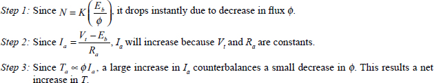
Step 4: The increased T increases the speed (N).
5.13 SPEED CONTROL OF DC MOTORS
From Equation (5.36), the speed control of DC motors can be carried in the following ways:
(i) Speed can be controlled by varying resistance in series with the armature circuit, which is called armature resistance control.
(ii) Speed can be controlled by varying the field flux (Φ). This method is known as field resistance control.
(iii) Speed can also be controlled by varying the applied voltage, which is called voltage control.
5.13.1 Armature Resistance Control
If a speed below the no-load speed is required, armature or rheostatic method is used. The supply voltage is constant and the rheostat connected in series with the armature is varied. By increasing the controller resistance, it is possible to decrease the potential drop of the armature and hence also the armature speed. Figures 5.5(a) and 5.5(b) show the method of connection to external resistance (Re) in the armature circuit of a DC shunt and series machine, respectively. In a shunt machine, flux (Φ) will not be affected. But in DC series machine, flux (Φ) will be affected. In both cases the motor runs at a lower speed if the value of Re is increased.
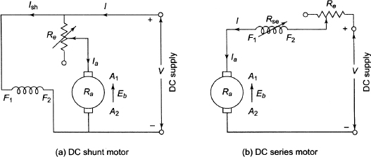
Figure 5.5 Armature Resistance Control of DC Motors
The speed (N) versus armature current (Ia) for DC shunt and series machines is shown in Figures 5.6(a) and 5.6(b), respectively.
Let us calculate the stalling current for the DC shunt motor.
If the load torque is constant, the speed is proportional to the potential difference across the armature. Figure 5.7 shows the circuit diagram of the armature control method, while Figure 5.8 shows the speed versus armature current characteristic.
Let Ia0 be the armature current at no-load and the armature resistance be Ra. Let Ia1 be the armature current when the controller resistance R is added to the armature resistance. The total armature resistance becomes Rt = R + Ra. Let N0 be the no–load speed and N1 be the speed of armature current Ia1.
![]()
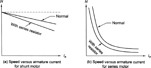
Figure 5.6 Speed Versus Armature Current for DC Shunt and Series Motors
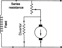
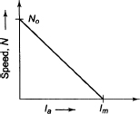
Figure 5.8 Speed Versus Armature Current Characteristic
Since the flux is constant for the shunt motor, we have

Equation (5.38) shows the linear relation between Rt and speed.
The load current Ia1 for which the speed N1 becomes zero is obtained by putting N1 = 0 in Equation (5.38).

Equation (5.39) shows the required maximum current for which speed becomes zero. This current is known as stall.ng current.
The drawbacks of this method are as follows:
(i) A large amount of power is lost in the external resistance Re.
(ii) This method gives the speed below normal value.
(iii) For a specified value Re, speed reduction is not constant. It varies with the motor load.
Example 5.9 The torque of the load driven by a 400 V DC shunt motor varies as the cube of the speed. The current taken by the motor is 40 A at a certain speed. Calculate the additional resistance required to be connected in series with the armature circuit to reduce the speed to 60 per cent of the original speed. The resistance is 0.35 Ω .
Solution
Vt = 400 V, Ia1 = 40 A = Ra = 0.35 Ω.
Let the resistance R be inserted in series with the armature to reduce the speed to 60 per cent of its original value.
![]()
We have the following relation [∴ N2 = 0.6 N1]
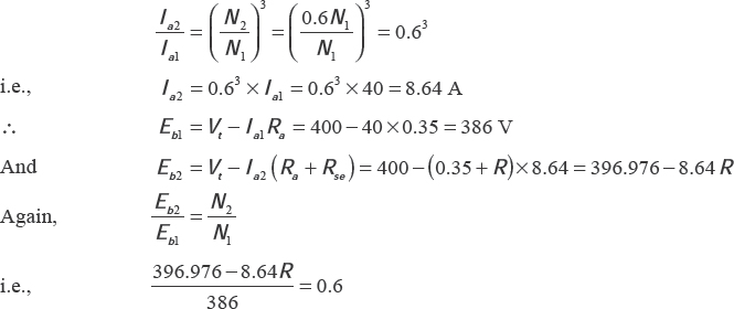
R = 19.14 Ω.
Therefore, the required additional resistance is 19.14 Ω to reduce the speed to 60 per cent of the original speed.
Example 5.10 A 220 V DC series motor has an armature resistance of 0.3 Ω and a field resistance of 0.2 Ω It runs at a speed of 700 rpm taking a current of 15 A. Calculate the resistance to be inserted in series with the armature to reduce the speed to 600 rpm. The input current remains constant. Assume that the magnetization characteristic is a straight line.
Solution

Let the resistance R Ω be connected in series with the fi eld to reduce the speed from 700 rpm to 600 rpm.
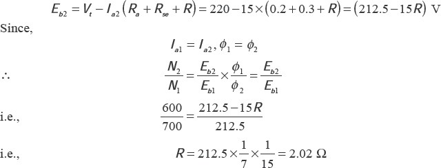
Therefore, the required additional resistance is 2.02 Ω.
5.13.2 Field Resistance Control
In this method, current through the field winding is controlled by using a variable resistor in series with the field coil in the DC shunt motor and DC series motor, shown in Figures 5.9 and 5.10, respectively.
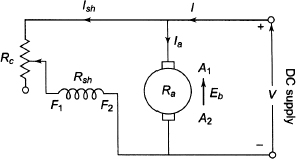
Figure 5.9 Field Resistance Control of DC Shunt Motor
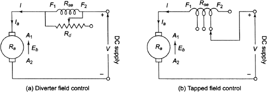
Figure 5.10 Field Control of DC Series Motor
In a series motor the field flux can also be changed by the following two methods:
(i) A variable resistance (Rd) is connected in parallel with the field coil as shown in Figure 5.10(a). This resistance Rd is called the diverter resistance.
(ii) The tapped field control can also be used as shown in Figure 5.10(b). In this case the ampere turns are varied by varying the number of field turns. The arrangement is used in electric traction.
Figures 5.11(a) and 5.11(b) show the speed–torque curves of DC shunt and series motors, respectively. The speed of the DC shunt and series machines is controlled by the variation of the field flux.
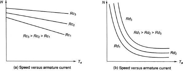
Figure 5.11 Speed Torque Characteristic of DC Shunt and Series Motors
Example 5.11 The armature and field resistances of a 200 V DC shunt motor are 0.4 Ω and 200 Ω respectively. When driving a load of constant torque at 500 rpm, the armature current is 20 A. It is desired to raise the speed from 500 rpm to 700 rpm. What resistance should be inserted in series with the shunt field circuit? Assume that the magnetic circuit is unsaturated.
Solution
![]()
Let the required resistance to be inserted in series with the shunt field circuit be R Ω.
We know that
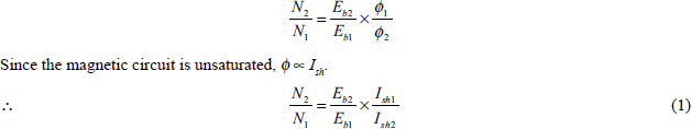
Due to constant torque,
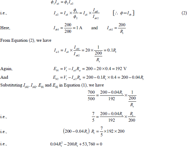

Therefore, the required additional resistance (R) = Rt – 200 = 85 Ω.
Example 5.12 A 240 V DC shunt motor has armature resistance of 0.25 Ω and draws a current of 40 A from the supply mains on half of full-load. The speed is to be increased twice the half-load speed. Determine the percentage change in flux if the torque of the motor remains constant.
Solution
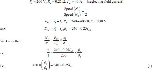
Again, the load torque remains constant, and we have
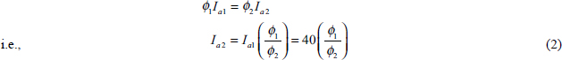
Using Equation (2), from Equation (1) we have
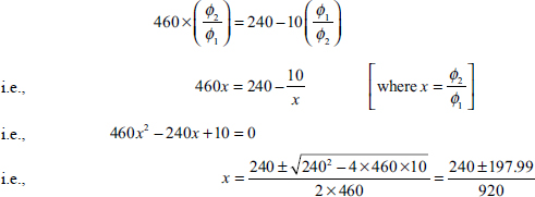
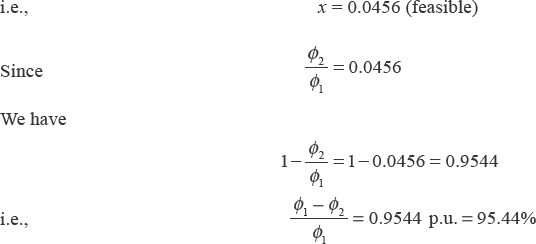
Therefore, percentage change in flux is 95.44.
Example 5.13 The input current of a 400 V DC series motor is 200 A when running at a speed of 800 rpm. When it runs at a speed of 1,000 rpm, it draws a current of 220 A. Calculate the value of resistance connected across the field circuit. The armature and field resistances are 0.15 Ω and 0.08 Ω, respectively.
Solution
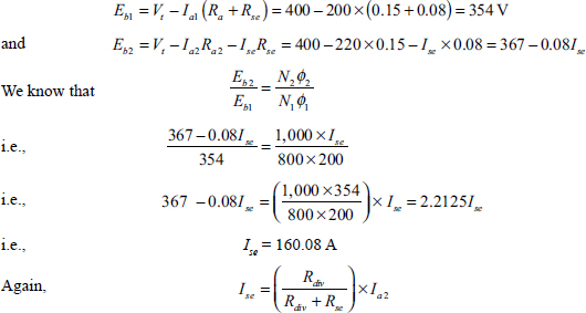
where Rdiv is the diverter resistance.
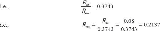
Therefore, 0.2137 Ω must be inserted across the resistance field.
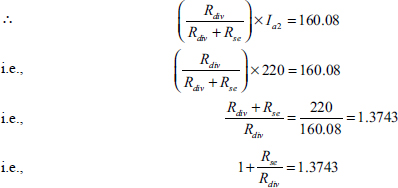
5.14 WARD-LEONARD CONTROL (VOLTAGE CONTROL)
The drawbacks of the earlier methods can be overcome by this method. When large motors are to be controlled, a separate motor-driven generator of suitable rating as shown in Figure 5.12 is used. The main motor field is supplied with full voltage independent of the armature, and thus it is a separately excited motor. The generator field is fed from a potential divider so that the field current and hence the terminal voltage of the generator can be varied from +V to –V, thus making it possible to control the speed of the main motor in either direction of rotation.
This method has the following advantages:
(i) Starting can be done without the necessity of series resistance starters.
(ii) Stepless control from standstill to maximum speed can be done in either direction.
(iii) No excessive high armature currents are required for rapid and instant reversal.
(iv) A wide range of speed from standstill to high speeds in either direction is possible.
This method has the following disadvantages:
(i) It is costly since it requires two extra machines of ratings comparable with the main motor.
(ii) The system has low overall efficiency because three machines are involved.
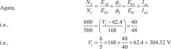
Example 5.14 A 220 V DC series motor takes 20 A while running at a constant speed. Its armature and field resistances are 0.3 Ω and 0.2 Ω, respectively. Calculate the resistance to be connected in series with the armature to reduce the speed by 40 per cent. Assume that the torque varies with the cube of the speed and flux is proportional to the current.
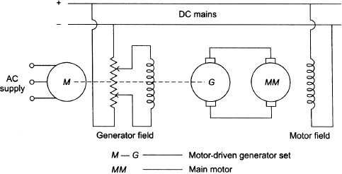
Figure 5.12 Ward–Leonard Method of Speed Control
![]()
Let the resistance R Ω be connected in series with the armature to get speed N2. For series motor,
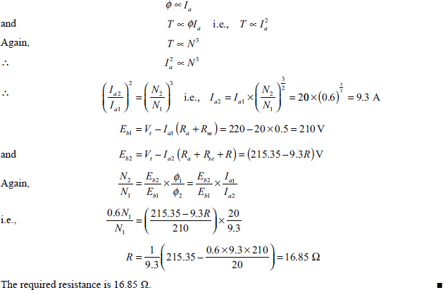
Example 5.15 A 220 V DC series motor takes 40 A and runs at 500 rpm while driving a fan load. The load varies as the square of the speed. The resistance between terminals is 1.3 Ω. It is required to raise the speed to 600 rpm by increasing the supply voltage. Find the required supply voltage. Assume that the flux varies directly as the current.
Solution
Resistance between terminals = 1.3 Ω
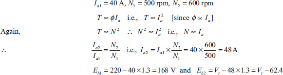
where Vt is the new supply voltage.
Therefore, the new supply voltage is 304.32 V.
5.15 NECESSITY OF A STARTER FOR DC MOTORS
During rest and at the time of starting, the back emf (Eb) of the DC machine is zero. The general expression for the armature current (Ia) of the DC machine is ![]() where Vt is the supply voltage, Eb is the back emf and Ra is the armature resistance.
where Vt is the supply voltage, Eb is the back emf and Ra is the armature resistance.
For Eb = 0, the expression for the armature current reduces to ![]() For a 250 V, 5 HP, 25 A, DC motor, Vt = 250 V, Ra = 0.5 Ω and
For a 250 V, 5 HP, 25 A, DC motor, Vt = 250 V, Ra = 0.5 Ω and ![]() which is 20 times rated full-load current. For the full voltage applied to the armature, the armature current becomes several times of its rated value. If this large current is allowed to flow through the armature, it will severely damage the motor. Hence, this high value of armature current should be prohibited for which a high value of external resistance must be connected to the armature in series only at the time of starting for 5 to 10 seconds. This limits the starting current to a safe value. This series resistance is known as the starting resistance, which is cut out gradually so that the motor achieves speed with simultaneous increase in the back emf. Once the back emf (Eb) reaches to the normal value, it regulates the motor armature current. Therefore, a variable resistance (Rs) must be included in series with the armature, shown in Figure 5.13, which is cut out manually or automatically, as the motor comes up to normal speed and full voltage is applied across the armature. This arrangement is known as starter. For the machine considered, if the current is limited to 25 A, the total resistance of the starter and armature should be 250/25 = 10 Ω. Therefore, the resistance of the starter alone must be 10 – 0.5 = 9.5 Ω
which is 20 times rated full-load current. For the full voltage applied to the armature, the armature current becomes several times of its rated value. If this large current is allowed to flow through the armature, it will severely damage the motor. Hence, this high value of armature current should be prohibited for which a high value of external resistance must be connected to the armature in series only at the time of starting for 5 to 10 seconds. This limits the starting current to a safe value. This series resistance is known as the starting resistance, which is cut out gradually so that the motor achieves speed with simultaneous increase in the back emf. Once the back emf (Eb) reaches to the normal value, it regulates the motor armature current. Therefore, a variable resistance (Rs) must be included in series with the armature, shown in Figure 5.13, which is cut out manually or automatically, as the motor comes up to normal speed and full voltage is applied across the armature. This arrangement is known as starter. For the machine considered, if the current is limited to 25 A, the total resistance of the starter and armature should be 250/25 = 10 Ω. Therefore, the resistance of the starter alone must be 10 – 0.5 = 9.5 Ω
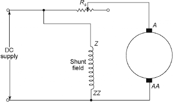
Figure 5.13 Principle of a Starter
5.16 MANUAL STARTER
In manual starters, the starting resistance is cut out manually until the motor speed increases, which is the face plate box starters and is used for starting shunt and compound motors of normal industrial capacity. These starters are classified as follows:
(a) three-point starter and
(b) four-point starter.
5.16.1 Three-point Starter
Figure 5.14 shows the internal wiring diagram of a three-point starter having three terminals, which are to be connected to the motors. Figure 5.14 is basically the same as that shown in Figure 5.13. The starter terminals L, A and F are connected to supply, armature and field, respectively. In Figure 5.14, SR is the starting arm, OLR is the overload or overcurrent release and NVR is the no-volt coil that holds on to the starting arm in the full running position during the normal operation of the motor and releases it when the supply is off. The main switch S is closed at first to start the motor and the starting arm (SR) is moved to the right slowly to make contact with the series starting resistance Rs. When SR touches the stud number 1, the field circuit is directly connected to the mains supply and the full value of starting resistance Rs comes in series with the armature. This reduces the starting current. As the arm SR further moves to the right, the resistance Rs is gradually cut out. The motor attains the rated speed when the arm SR is in the ON position and the starting resistance Rs is completely cut out and the armature current totally depends on the armature resistance now. The spring is provided in the starter to restore the arm SR to OFF position. When the supply fails, it keeps the arm SR at the OFF position. An electromagnet NVR energized by the field current is used to keep the arm SR in the ON position against the force of the spring. This electromagnet NVR is also known as the hold-on coil or no-voltage release. During normal operating condition, this hold on coil will hold the arm SR so that the motor runs at the normal speed. When the failure of power or disconnection of supply voltage or break in field circuit occurs, this electromagnet gets energized and releases the arm. This arm will be pulled back to the OFF position by the force of the spring, which prevents the stationary armature being connected to the supply voltage even after restoration of the supply voltage. If the field circuit becomes open, the arm SR immediately comes back to the OFF position and this prevents the motor from running away, which is great advantage of connecting the arm SR in series with field coil. During the ON position of the arm SR, the whole of the starting resistance Rs comes in series with the field winding resistance. Although the field winding resistance is very high, usually 200 – 300 Ω, the inclusion of the starting resistance decreases the field current by 2 to 4 per cent. To avoid this even small amount of current, a copper strip SR stud number 1 and the field current will now pass through this arc only and Rs will be bypassed. The overload release (OLR) consists an electromagnet connected to the supply line. The rod M gets lifted when the armature current exceeds a certain preset value and it short circuits the NVR. Hence, the arm SR will be released and it comes back to its original OFF position since the more accurate and reliable devices such as circuit breakers or magnetic conductors are used now instead of this OLR.
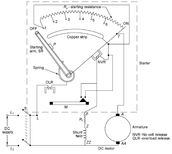
Figure 5.14 Three-point Starter
5.16.2 Four-point Starter
Figure 5.15 shows a four-point starter in which the resistance Rf is connected in series. If the value of Rf is increased, the field flux will decrease and hence the speed will increase ![]() If this resistance is very large, the field current will be very small. The hold on coil will not be able to hold the arm SR in ON position against the pull of the spring and hence the motor will be switched off from the supply, which is the main disadvantage of the three-point starter. Hence, the three-point starter cannot be used with the variable speed motors. For such applications, four-point starters are used.
If this resistance is very large, the field current will be very small. The hold on coil will not be able to hold the arm SR in ON position against the pull of the spring and hence the motor will be switched off from the supply, which is the main disadvantage of the three-point starter. Hence, the three-point starter cannot be used with the variable speed motors. For such applications, four-point starters are used.
A four-point starter is similar to a three-point starter. The only difference is that the hold-on coil is taken out of the field circuit and connected directly across the mains supply voltage with the help of a protective resistance Rp. The function of a four-point starter is similar to a three-point starter. When the arm SR is in contact number 1, the line current will have the following three paths:
(i) through the starting resistance Rs,
(ii) through the shunt field winding and rheostat winding and
(iii) through the hold-on coil and protective resistance Rp.
The field current in this case will not flow through the hold-on coil unlike the three-point starter. The variation of resistance Rf to control the speed will not affect the electromagnetic pull of the hold-on coil in this case.
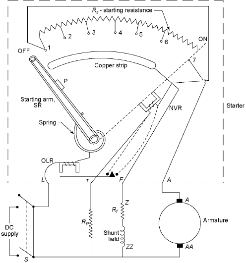
Figure 5.15 Four-point Starter
5.17 AUTOMATIC STARTERS
To start a motor at remote location or to start a large motor, it is desired that the starter to take it to its normal speed. The small motors which are not in remote locations are started by manual starters. Difficulties are encountered to start large motors. The skill with which the operator operates in manually operated starters depends on his/her experience. An overcautious operator may take too much times or a careless operator may exceed the maximum permissible currents. It is always preferable to use automatic starters to avoid these cases, and it will interrupt the conditions of the load and function accordingly. There are the following types of automatic starters:
(i) the time element starter,
(ii) the back emf type,
(iii) the shunt current-limit type and
(iv) the series current-limit type.
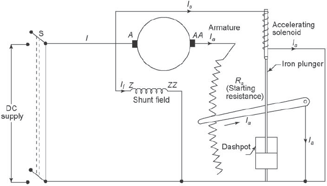
Figure 5.16 Three-element Automatic Starter
5.17.1 Time Element Starter
Figure 5.16 shows a three-element automatic starter in which the resistance in series with the armature is reduced by a certain amount during each succeeding interval regardless of load of the motor. The full value of starting current is connected with the armature initially to limit the current to a safe value. The full voltage appears across both the field winding and the accelerating solenoid. Due to the flow of current through the solenoid, it immediately begins to draw the iron core upwards and Rs is gradually cut out from the armature circuit. The dashpot has a hole through which the oil can flow known as orifice. More time will be consumed to cut out Rs if the size of orifice is smaller. To build up the speed and back emf and to maintain the starting current at the maximum safe value during the motor acceleration period, the proper size of the orifice is designed. When the motor achieves its rated speed, the starting resistance is completely cut out.
The following are the advantages of this starter:
(i) It is cheaper.
(ii) The wiring is simple.
(iii) The starting is generally guaranteed.
The main disadvantage is that the load cannot be sensed; that is, the starting resistance is cut out whether the load is low or high.
5.17.2 Back emf Starter
Figure 5.17 shows a back emf starter and its operation depends on the back emf developed across the motor armature. A solenoid is connected directly across the armature and hence it functions as per the voltage of armature that is slightly higher than the back emf. The variation of back emf and the speed of the motor are shown in Figure 5.18.
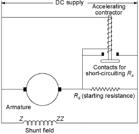
Figure 5.17 Back emf Starter
At the time of starting, the armature current that flows through the starting resistance reduces the voltage to be applied to the armature. Therefore, the accelerating conductor will not immediately close its contacts due to low voltage across its operating coil. As the motor picks up speed, the armature current and the voltage drop across Rs reduce due to the rising back emf. The voltage across the armature increases at the same time when voltage increases to a given value, say at time t1. The accelerating contactor closes at this time and Rs gets short circuited. Hence, full voltage is applied across the armature, therefore resulting increase in starting current. This causes the motor speed to increase continuously till it reaches to its rated speed. The armature current again reduces to its normal value. In Figure 5.17, only one resistor and a accelerating contactor have been shown, but in actual practice the starters for large motors have several contactors and large numbers of steps in starting resistance. Figure 5.18 shows the variation of back emf and speed of the motor with time. The motor speed increases slowly for heavy load, and the rise in voltage on the accelerating contactor operating coil is delayed so that Rs is not cut out until the rise in speed and back emf permits the contactor to loose.
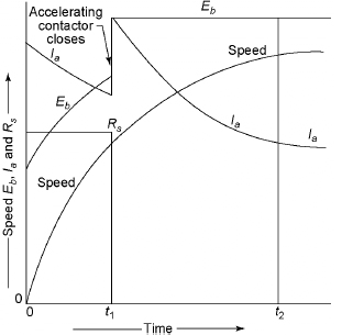
Figure 5.18 Variation of Back emf and Speed of the Motor with Time
It is possible to anticipate the load and the starting resistance can be cut out accordingly. This type of starters has low cost and simple wiring. The speed of the motor becomes erratic if the line voltage varies.
5.17.3 Shunt Current-limit Starter
Figure 5.19 shows the wiring diagram of the shunt current-limit starter, which uses accelerating contactors with shunt-type operating coils. The full voltage is applied across the shunt-type operating coils. These types of starters can overcome the disadvantages of the back emf starter. There are interlocking series relays and the operation of these relays can be overcome by the starting current. As soon as the series relay closes the contacts, the shunt operating coils of the accelerating coils are energized. This cuts a portion of Rs from the armature circuit. Since the contactors are in shunt with the armature and the closure of the series relay is determined by the magnitude of the armature current, these relays are called shunt current-limit starter.
This starter operates in conjunction with a push button starter. The no-voltage release coil is energized due to pressing the ON button momentarily and the holding relay contacts as well as the line contacts are closed. The series relay contact is released mechanically and hence its contacts would close. Due to the flow of armature current through the series coil, its core will be held up and its contacts are kept open.
The back emf increases due to the increase in the speed and hence the armature current reduces weakening the flux of the series relay. Therefore, the relay contacts get closed. The coil of the accelerating contacts gets energized and hence its contacts get closed. This short circuits Rs and series relay. Therefore, the full-line voltage is safely applied across the armature. As long as the motor is connected to the supply line, the accelerating contractor contacts remain closed. To interrupt the current through the no-voltage release coil, the OFF button is to be pushed. This also opens the holding relay contacts, the line supply contacts as well as the series relay contacts. Finally, the motor will be disconnected from the supply mains. Although one starting resistor is shown in Figure 5.19 to simplify the drawing, but in practice two or more resistors are used. Using additional starting resistor and interlocking series relay, the starting resistance is cut out in steps as the motor builds up its speed. In spite of the fluctuations of the supply voltage, the armature current is reduced to a safe value because the starting resistance of the armature circuit is cut out only after the speed had built up. For a heavy load the motor cannot accelerate immediately. The back emf also cannot build up sufficiently to reduce the current through the series relay to make its contacts get closed and hence Rs remains open in the circuit. This protects the motor against the overload. The main disadvantage is that the accelerating unit is very complicated and expensive.
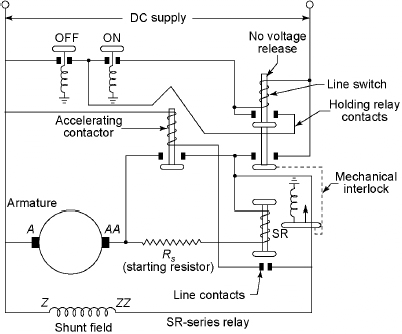
Figure 5.19 Shunt Current-limit Starter
5.17.4 Series Current-limit Starter
Figure 5.20 shows the series current-limit starter that uses the less complicated equipment and performs the same job as done by shunt current-limit starter without using interlocking series relay. The accelerating contacts are designed in such a way that they open immediately after the starting current starts rising. The contactor closes as soon as the current falls to a predetermined value and the starting resistance is cut out. From Figure 5.20, the relay coil that operates the accelerating contractor is connected in series with the armature.
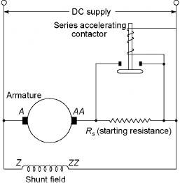
Figure 5.20 Series Current–limit Starter
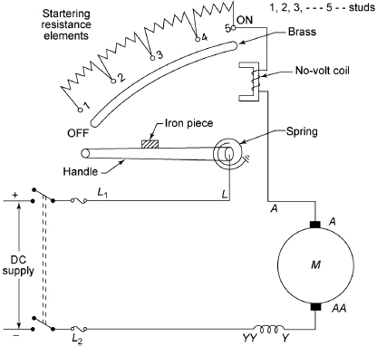
Figure 5.21 No-load Release-type Series Motor Starter
5.18 STARTERS FOR DC SERIES MOTORS
Figure 5.21 shows no-load release type of starter for the series motor in which series resistance is inserted in the armature at the time of starting. The starting resistance is gradually cut out from the circuit. The no-load type of starter is preferable because the speed increases dangerously to high value due to a low value of load drops. The strength of the no-voltage coil decreases due to decrease in the load current. Hence, the handle flies back to the OFF position due to the spring force. Due to failure of supply during the operation of motor, the no-volt coil gets demagnetized and hence the handle from the ON position is released.
5.19 DC SHUNT MOTOR STARTER DESIGN
A shunt motor with n resistance elements, (n + 1) steps or (n + 1) studs has been shown in Figure 5.22.
Let
where Ra is the armature resistance including brushes.
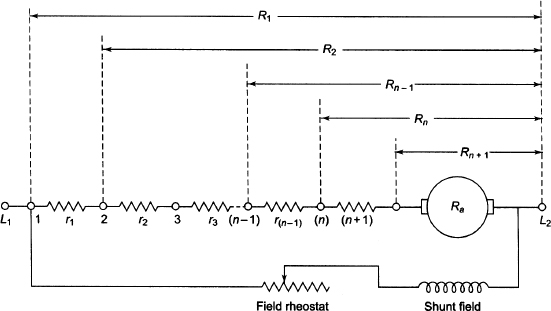
Figure 5.22 Starter Resistance for DC Shunt Motor
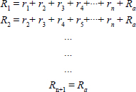
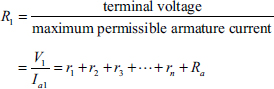
At the instant when the motor is switched on, the total armature circuit resistance, R1, should be equal to
With the handle on stud 1, the motor accelerates, counter emf develops and, as a result, the armature current starts decreasing from Ia1. When the current has dropped to minimum current Ia2, then the counter emf with the handle on stud 1 is given by

At stud 1, as soon as the current drops to Ia2, the resistance r1 is cut out by moving the handle to stud 2. During the notching up process from stud 1 to stud 2, the speed and, therefore, Ea1 do not change. At stud 2, just after r1 is cut out, the current shoots up again to Ia1.
![]()
From Equations (5.40) and (5.41),
![]()
Following the above procedure for other study, we have
![]()
From Equation (5.42), we have

Continuing the analysis further, it can be proved that

Example 5.16 A 220 V, 1,500 rpm, DC motor has a full-load armature current of35 A. It is proposed to design a starter, which restricts the maximum armature current during start to 70 A. For design purposes, the minimum current during starting is to be restricted to 35 A, and the series resistance in the armature circuit is cut out in steps when the current falls to 35 A. Calculate the maximum series resistance used in the starter and the amount of resistance cut out during each of the first two steps. The armature resistance of the DC motor is 0.45 Ω .
Solution
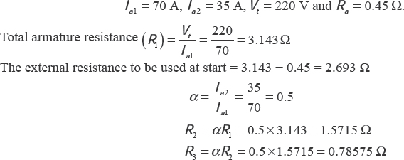
The resistance cut out in the first step = R1 – R2 = 3.143 – 1.5715 = 1.5715 Ω
The resistance cut out in the second step = R2 – R3 = 1.5715 – 0.78575 = 0.78575 Ω
5.20 ELECTRIC BRAKING
Using friction or electric braking, it is possible to bring a motor and its load to rest quickly. In friction braking, it is difficult to get smooth stop. In electric braking it is possible to stop the motor smoothly. There are three kinds of electric braking: (i) rheostatic or dynamic, (ii) plugging and (iii) regenerative braking. Friction braking is required for holding the motor even after it has been brought to rest.
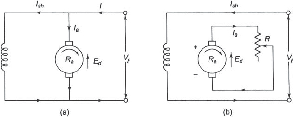
Figure 5.23 Rheostatic or Dynamic Braking
5.21 ELECTRIC BRAKING OF SHUNT MOTORS
Shunt motors are brought to rest using electric braking. The three types of braking – rheostatic or dynamic, plugging and regenerative – are discussed below.
5.21.1 Rheostatic or Dynamic Braking
Figure 5.23(a) shows the rheostatic braking in which the armature of the shunt motor is disconnected from the supply and it is connected across a variable resistance R. The field winding is kept undisturbed, and this braking is controlled by varying the series resistance R. This method uses the generator action in a motor to bring it to rest.
From Figure 5.23(b), the armature current is given by
The braking torque is given by
Therefore, TB decreases and the motor slows down. When the motor comes to stop, TB becomes zero.
5.21.2 Plugging or Reverse Breaking
Figures 5.24 shows plugging or reverse braking. In this method, the armature terminals are reversed to rotate the motor in the reverse direction, and the applied voltage Vt and the back emf Eb start acting in the same direction. To limit the armature current, a resistance is inserted in series with the armature during reversing the armature.
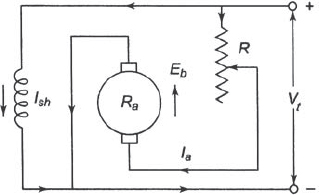
Figure 5.24 Plugging or Reverse Braking
Compared to rheostatic braking, this method gives greater braking torque. In this braking, power is drawn from the supply and it is dissipated by R in the form of heat. In spite of zero motor speed, there is still braking torque.
5.21.3 Regenerative Braking
In regenerative braking, Eb is greater than V Figure 5.25 shows regenerative braking. The direction of Ia and the armature torque TB is reversed. Regenerative braking is used for downgrade motion of an electric train.
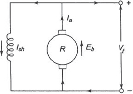
Figure 5.25 Regenerative Braking
5.22 ELECTRIC BRAKING OF SERIES MOTOR
5.22.1 Rheostatic Braking
Figure 5.26 shows the rheostatic braking of a DC series motor. In this method, the motor is disconnected from supply. The field connection is reversed and the motor is connected through a variable resistance, R.
5.22.2 Plugging or Reverse Current Braking
Figure 5.27 shows plugging or reverse current braking and it is similar to that of the shunt motor.
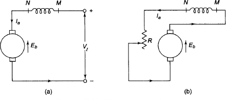
Figure 5.26 Rheostatic Braking
5.22.3 Regenerative Braking
This type of braking is impossible in series motors. To achieve it, modifications are required because reversal of current would reverse the field current and hence Eb.
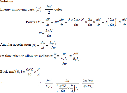
Example 5.17 If A is the number of parallel paths, P is the number of poles, J is the moment of inertia of the moving parts (kg m2), Φ is the flux in Wb, Z is the number of conductors and Ia is the accelerating current which is assumed to be constant of a DC motor, prove that the time taken by the motor
![]()
Figure 5.27 Plugging or Reverse Current Braking
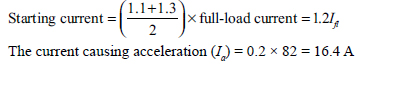
Example 5.18 A 500 V, 52 HP(metric), shunt motor is running at full-load at 550 rpm and takes 82 A. Calculate the time to attain full-load speed when started from rest against full-load torque. The starting current fluctuates between 1.1 and 1.3 times the normal rated current. The efficiency constant at full-load value during starting period is assumed to be constant. Take the moment of inertia of the system 22 kg m2.
Solution
Full-load current = 82 A
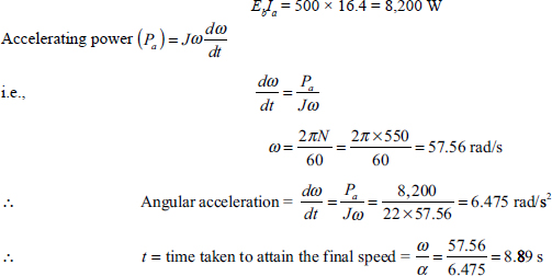
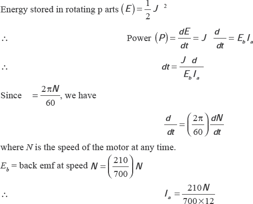
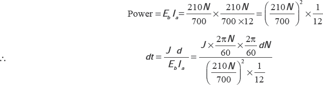
Example 5.19 Calculate the required time for a shunt motor to fall in speed from 700 rpm to 250 rpm, keeping the excitation constant. The armature is connected across a resistance of 12 Ω. The induced emf at 750 rpm is 210 V. The moment of inertia of the armature is 24.2 kg-m2. Assume that(i) the motor has negligible loss and(ii) the factional torque is 12.52 N-m.
Solution
Back emf (Eb) at 700 rpm = 210 V
![]()
Power wasted during running down = 210 × 17.5 = 3,675 W.
Case I: Negligible motor loss
Since EbIa is negative, we have
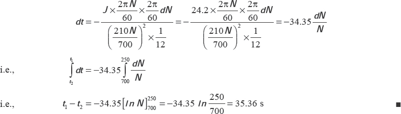
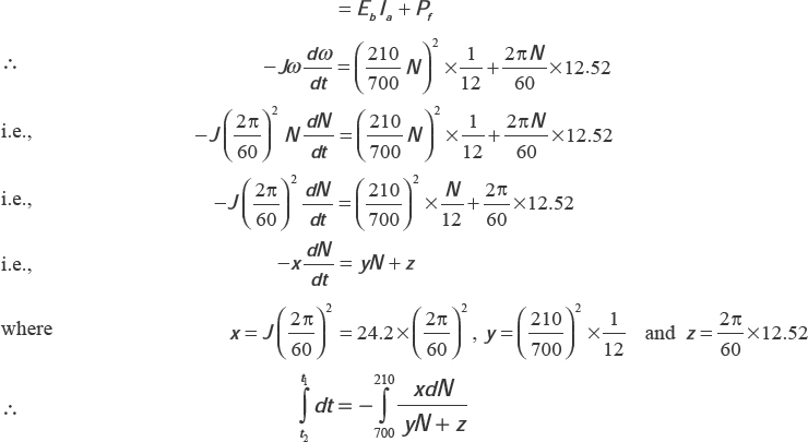
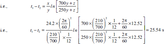
Case II: Frictional torque = 12.52 N-m
Wastage of power due to friction at any speed (N) is given by
![]()
where Tf is the torque due to friction.
Wastage of power in retardation = power wasted in load + power wasted in friction
5.23 TESTING OF DC MACHINES
The tests that are performed on DC machines are as follows:
- open-circuit characteristic,
- load characteristics,
- determination of efficiency curve and
- temperature rise test
The first two have already been discussed. There are three methods to determine the efficiency of DC motors:
- Direct method: In this method, the generator or motor is put at full-load and the total power developed by it is wasted. An example of direct test is break test. Direct test is generally used for small machines. Although this method is very simple, it is very difficult to measure the mechanical power input in case of the generator and output in case of the motor. The brake must be tight before starting a series motor if brake is applied in the series motor. If this is not done, the armature may get damaged and fly wheel broken to pieces.
- Indirect method: Measurement of losses and calculation of efficiency are carried out in this method. Swinburne test is the simplest example of the indirect method. No loading is required for calculation of losses. There is no difficulty in applying this method to large machines. The disadvantage of this method is that the machine is run light during the test and so it does not give any indication of temperature rise at load or of commutating qualities of the machine.
- Regenerative method: In this method, two identical machines are required. One of them will act as a motor to drive the other as a generator, and these are mechanically coupled. The machine working as a generator feeds back power to the motor. The total power drawn from the supply is only used for supplying the internal losses of the two machines. It is possible to test very large machines as the power required is very small. Hopkinson test is a regenerative test for determining efficiency of a DC machine.
5.24 BRAKE TEST
Figure 5.28 shows the brake test of a DC motor. This test is used to determine the efficiency of comparatively small motors. The motor is loaded directly by means of a mechanical brake or by means of an eddy current or a calibrated air fan.
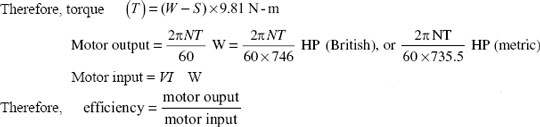
Figure 5.21 shows a common type of mechanical brake used in testing – the rope brake. One end of the rope is fixed to a spring balance which is further attached to a fixed hook, whereas the other end is attached to a hook or pan to which load is added.
The load on the motor is adjusted to carry the full-load current after its starting.
Let W be the suspended weight (kg-wt), S be the spring balance reading(kg-wt), R be the radius of pulley(m) and N be the speed(rpm).
This method has the following disadvantages:
- It is not possible to measure the output power directly.
- It is not possible to use this method for determining internal losses and efficiency of large motors.
Example 5.20 A 400 V DC shunt motor gave the following readings during brake test:
supply voltage = 400 V, armature current = 55 A, shunt field current = 4 A, length of the brake arm = 100 cm, reading of spring balance at the end of brake arm = 30 kg-wt and speed = 700 rpm. Determine (i) the torque developed, (ii) British Horse Power (BHP) and (iii) efficiency.
Solution
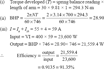
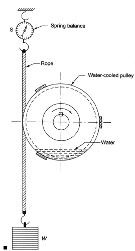
Figure 5.28 Brake Test
5.25 SWINBURNE’S TEST
Losses are measured separately in this method, and efficiency at any desired load is predetermined. The iron and friction losses can be determined by measuring the input to the machine at no-load. The machine is run as a motor at normal voltage and speed. The copper losses are calculated from measured values of the various resistances. This method is only applicable to level compounded and shunt motors. Figure 5.29 shows the circuit diagram of Swinburne’s test.
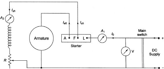
Figure 5.29 Swinburne's Test
Let Vt be the supply voltage, I0 be the input armature current at no-load(measured by ammeter A1) and Ish be the shunt field current(measured by ammeter A2) for Figure 5.29.
Therefore, no-load armature current (Ia0) = I0 – Ish, no-load input = VtI0 W, power input to the armature = Vt (I0 – Ish) W and power input to shunt = VtIsh W.
The no-load input power supplies the following:
(i) iron loss in core,
(ii) friction losses,
(iii) windage losses and
(iv) armature copper losses.
During calculation of copper losses, the hot resistance of the armature must be used. For this, stationary measurement of armature circuit resistance at room temperature of, say, 15°C, is made by passing current through the armature from a low-voltage DC supply.
The hot resistance after allowing a temperature rise of 50°C is given by

where α0 is the temperature coefficient of resistance at 0°C.
Constant losses = no-load input - no-load armature copper loss
After getting the constant losses of a machine, its efficiency at any other load can be calculated as follows: Ia = I – Ish, where I is the input current at which the efficiency is required for motoring mode; and Ia = I + Ish, where I is the load current at which the efficiency is required for generating mode.
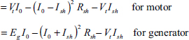
5.25.1 Motoring Mode
Motor input = VtI, armature Cu loss = Ia2 Ra = (I − Ish)2 Ra and shunt field Cu loss = VtIsh, where I is the input current and Vt is the supply voltage. Constant losses have been calculated above.
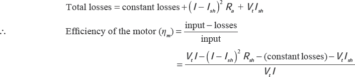
5.25.2 Generating Mode
Output = Vt I, armature Cu loss = Ia2 Ra = (I + I)2 Ra and shunt field Cu loss = VtIsh, where Vt is the output voltage and I is the load current.
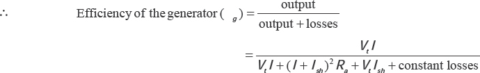
This method has the following advantages:
- This method is convenient and economical for testing of DC machines because power required is small.
- Since constant losses are known, efficiency can be predetermined at any load.
In spite of the above advantages, this method has the following disadvantages: - The change in iron losses from no-load to full-load is not taken into account. At full-load, the flux is distorted due to armature reaction, which increases iron losses in some cases by 50 per cent.
- It is difficult to know whether commutation is satisfactory or not at full-load because the test is conducted at no-load.
Since series motors cannot be operated at no-load due to their high speed, this test is not applicable to series motors.
Example 5.21 A 400 V DC shunt machine takes 7 A at no-load when operates as a motor. The armature current and field resistances are 0.25 Q and 200 Q, respectively, when measured at room temperature. Calculate the efficiency of the machine:
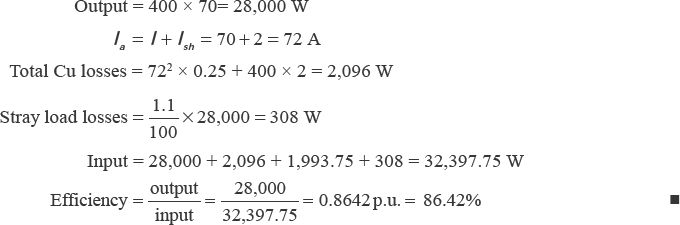
(i) when runs as a motor taking a line current of 70 A at 400 V and
(ii) when runs as a generator delivering a line current of 70 A at 400 V.
The stray load loss is 1.1 per cent of the output. Neglect the increase in resistance due to temperature rise.
Solution
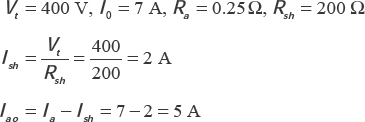
No-load Cu loss = 52 – 0.25 + 400 – 2 = 806.25 W
No-load input = 400 – 7 = 2,800 W
∴ Mechanical and iron losses (i.e. constant losses) = 2,800 – 806.25 = 1,993.75 W
(i) Efficiency when working as a motor
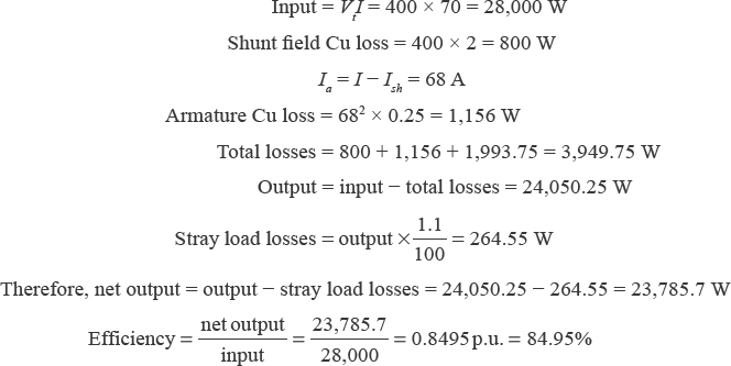
(ii) Efficiency when working as a generator
5.26 HOPKINSON’S TEST (BACK-TO-BACK TEST)
In this test, full-load test can be carried out on two identical shunt machines without wasting their outputs. Figure 5.30 shows the connection diagram of this test on a pair of shunt machines
Figure 5.30 shows two machines, which are mechanically coupled. Their fields are adjusted in such a way that one runs as a generator and the other as a motor. The power produced by the generator is utilized by the motor driving the generator. The power taken from the supply is used to supply losses only. Two identical machines of any size can be tested under full-load conditions. This method is very useful to determine the efficiency as well as a heat run test for the temperature rise. The following procedures are followed:
- The machine M in Figure 5.23 is started through a starter. Its field excitation is adjusted to take it to normal speed. The machine M drives the machine G. The switch S is kept open.
- The excitation of machine G is gradually increased so that the reading of the voltmeter (V1) becomes zero. The switch S is closed and the machine G is at the floating stage. The shunt field regulators are adjusted to put any desired load.
The input power is used to meet losses only.
Let Vt be the supply voltage, I1 be the output current of the generator, I2 be the current taken from the supply, I3 be the exciting current of the generator, I4 be the exciting current of the motor and Ra be the armature resistance of each machine.
Motor input = Vt (I1 + I2)
Generator output = Vt I1
If the efficiency of both the machines is η, we have
Output of the motor = η – input = η Vt (I1 + I2) = generator input
Output of the generator = η – input = η – η Vt (I1 + I2) = η2 Vt (I1 + I2)
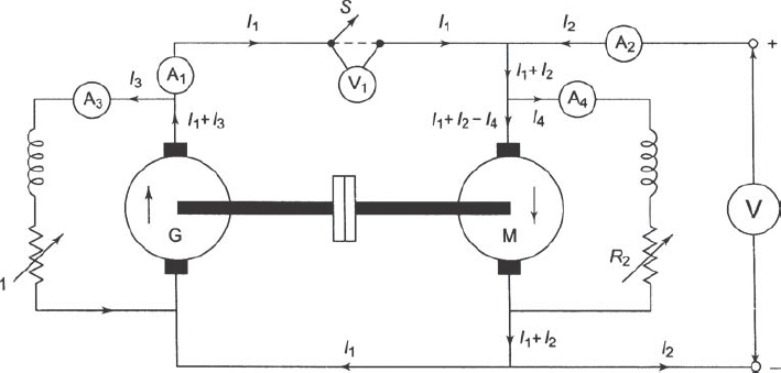
Figure 5.30 Hopkinson's Test
In practice, it is very difficult to get two machines having identical efficiency. Hence, the following analysis is done taking different efficiency of the machines.
Armature Cu loss in generator= (I1 + I3)2 Ra
Shunt Cu loss in generator = VtI3
Armature Cu loss in motor= (I1 + I2 − I4)2 Ra
Shunt Cu loss in motor = VtI4
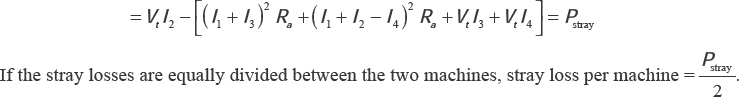
The overall losses of the motor and generator are equal to the power supplied by the mains.
Power taken from supply = VtI2
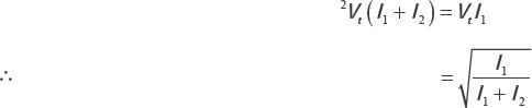
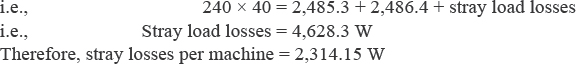
Therefore, stray losses for the set
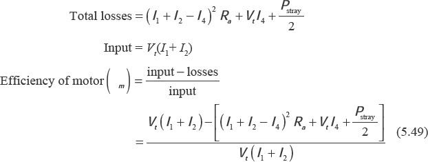
For the generator:
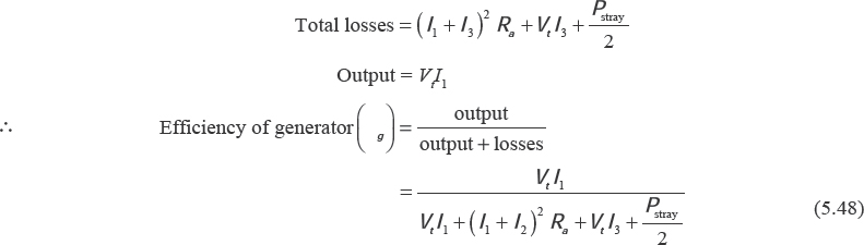
For the motor:
This test has the following advantages:
- This test is very economical since power required is small.
- Commutation and temperature rise of the machine can be studied properly.
- Since the test is conducted at full-load, any change in iron losses due to flux distortion at full-load is taken into account.
The main disadvantage of this test is that two identical machines cannot be obtained very easily.
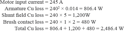
Example 5.22 Hopkinson’s test on two identical shunt machines gave the following readings: supply voltage = 240 V, field currents = 6 A(generator) and 5A(motor), line current = 40 A, armature current of motor = 240 A, armature resistance of each machine = 0.014 Q, voltage drop/brush = 1 V.
Find the efficiency of each machine
Solution
Vt = 240 V, Ish1 (field current of generator) = 6 A, Ish2 (field current of motor) = 5 A, supply current = 40 A, armature current of motor = 240 A, armature resistance of each machine = 0.014 Ω, voltage drop per brush = 1 V
From Figure E5.1, we have the following:
For motor:
For generator:
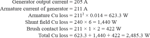
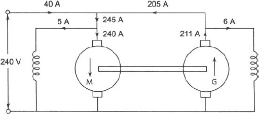
Figure E5.1
Total power input from supply = total losses in the set
Motor efficiency:
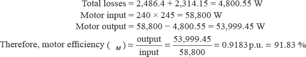
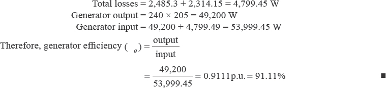
Generator efficiency:
5.27 SEPARATION OF LOSSES IN A DC MACHINE
The main purpose of this test is to segregate various losses in a DC machine into their component parts. The DC machine is run at no-load by varying the speed, and its excitation is kept constant. The frictional loss and the windage loss of the shunt motor are proportional to N and N2, respectively, where N is the speed at any instant. The mechanical losses (Wm) can be expressed by
![]()
where A and B are constants.
The iron loss consists of hysteresis loss and eddy current loss, which are proportional to

where t is the thickness of laminations.
The frequency of eddy current is expressed by
![]()
If Bmax is kept constant, iron loss can be expressed as
![]()
Therefore, the total losses become
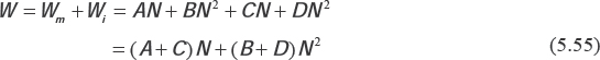
Dividing both sides by N, we have
![]()
Figure 5.31 shows the graph where y-axis and x-axis represent ![]() and N, respectively, and PQ shows the straight-line relationship.
and N, respectively, and PQ shows the straight-line relationship.

For constant excitation, Bmax remains constant and the constants A and B will remain unchanged. The constants C and D change to C′ and D′, respectively, when the motor runs at different excitations. Equation (5.56) becomes
![]()
This relationship is plotted in Figure 5.31 where it represents another straight-line SR such that
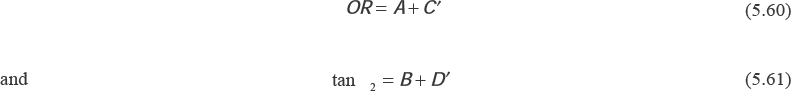
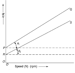
Figure 5.31 Separation of Losses
From Equations (5.57) and (5.60), we have
![]()
From Equations (5.58) and (5.61), we have
![]()
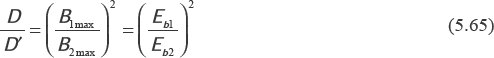
If B1max and B2max are the flux densities at two different excitations, we have
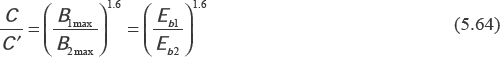
where Eb1 and Eb2 are the back emf developed at two different excitations at any given speed. Similarly,
The value of ![]() can be found out from the test described below and hence the ratio
can be found out from the test described below and hence the ratio ![]() can be determined. Therefore, the values of C, C′, D and D′ can be known. From Equations (5.57) and (5.58), A and B can be found out if and only if the curves PQ and RS shown in Figure 5.31 are known at two different excitations
can be determined. Therefore, the values of C, C′, D and D′ can be known. From Equations (5.57) and (5.58), A and B can be found out if and only if the curves PQ and RS shown in Figure 5.31 are known at two different excitations
Figure 5.32 shows the circuit diagram to determine the separation of losses of a DC shunt motor by exciting the machine separately. The motor is run at no-load. The switch ‘S’ is closed. The series resistance (Rs) is adjusted to have a high value in the armature circuit and the flow of maximum field current in the field. The resistance Rs is fully cut off so that the rated voltage is applied across the armature. By changing the excitation, the speed of the motor is adjusted to the rated value. When the motor runs at rated speed and the rated voltage is applied, the motor is said to be normally excited. The speed, the voltage across the armature and the armature current are noted. The excitation is now kept constant, and the speed of the motor is varied by varying the armature voltage with the help of Rs. Restoring more resistance in armature circuit, speeds differing by 100 rpm are obtained and the measurement at each speed is noted down.
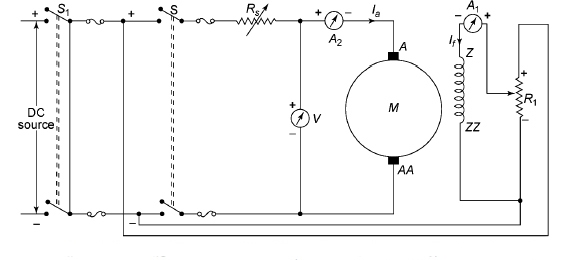
Figure 5.32 Schematic Diagram of the Separation of Losses of a DC Shunt Motor
The no-load loss at any given speed is expressed as follows:
![]()
If W is known, ![]() can be computed for each value of the speed. The plot of
can be computed for each value of the speed. The plot of ![]() versus N is plotted to obtain the curve PQ. Let the line RS be plotted with
versus N is plotted to obtain the curve PQ. Let the line RS be plotted with ![]() in the y-axis and N along the x-axis. Let line RS represent the graph at the reduced 0.75 × excitation for the rated speed. The two straight lines will show some divergence between them and the constants A, B, C and D can be computed. Using Equations(5.51)–5.52), the different loss components can be obtained at any desired speed at the normal excitation. The advantages of this method are as follows:
in the y-axis and N along the x-axis. Let line RS represent the graph at the reduced 0.75 × excitation for the rated speed. The two straight lines will show some divergence between them and the constants A, B, C and D can be computed. Using Equations(5.51)–5.52), the different loss components can be obtained at any desired speed at the normal excitation. The advantages of this method are as follows:
(i) The various losses can be divided into their component parts.
(ii) The method is simple to carry out with very low power loss.
The main disadvantage of this method is that the experiment must be carried out very carefully to avoid the erroneous results.
5.28 RETARDATION OR RUNNING TEST
This test is applied to shunt motors and generators to obtain stray losses. After determining the armature and shunt field Cu losses, the efficiency of the motor can be calculated. During testing, the machine is speeded up slightly beyond its normal speed and the supply is removed. But field excitation is continued. Therefore, the armature slows down and its kinetic energy is used to meet the rotational losses, that is, friction, windage and iron losses.
Kinetic energy of the armature is given by
![]()
where J is the moment of inertia of the armature and ω is its kinetic energy. Since, rotational losses = rate of loss of KE
![]()
5.28.1 To Find 
Figure 5.33 shows the circuit connection. A voltmeter V is connected across the armature. Since the speed indicator suitably graduates the voltage across the armature, this voltmeter is required. After removing the supply, the armature speed decreases and reading of the voltmeter also falls. The reading of different voltage falls in different periods is noted down. Figure 5.34 shows the plot of time and speed.
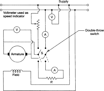
Figure 5.33 Retardation or Running Test
At the point X, tangent YZ is drawn. From Figure 5.34, we have
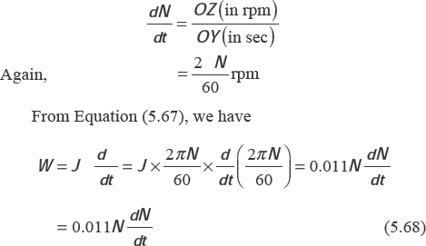
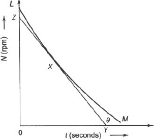
Figure 5.34 Speed-Time Curve in Retardation Test
5.28.2 To Find J
5.28.2.1 First Method
In this method, J is calculated. After obtaining the speed–time curve, a flywheel of known moment of inertia (J′) is keyed to the shaft. Again, speed–time curve is obtained. ![]() (without adding the flywheel) and
(without adding the flywheel) and ![]() (after adding the flywheel) are calculated for any given speed.
(after adding the flywheel) are calculated for any given speed.
Since losses are the same in both cases,

5.28.2.2 Second Method
In this method, J is eliminated. This method is more popular and more convenient. The following procedures are generally adopted:
- The time required for decrease in speed, say 5 per cent, is noted down.
- A known retardation torque is applied and the time for the same drop is noted down.
Using the circuit, shown in Figure 5.33, the retarding torque is applied electrically. The armature is connected to a double-throwing switch.
At first, the machine is brought to the rated speed. The time required to decrease the voltage from 250 V to 230 V is noted down. The switch is thrown to the supply side and the motor is brought to the rated speed. The switch is again thrown to the other side so that the non-inductive resistance (R) across the armature is connected. The flow of current(I) results in loss I2(Ra + R). The means of initial and final value of δN are taken to find this extra power loss because the value of I will change with change in speed. Let this power be P´.
Let P be the iron and mechanical losses of motor at mean speed, δN be the change in speed, t1 be the time of slowing down without extra loss, and t2 be the time of slowing down with extra loss.

Example 5.23 A DC machine running at 700 rpm is put to a retardation test. The time taken at the speed to fall from 730 rpm to 670 rpm is(a) 27 seconds with no excitation, (b) 10 seconds with full excitation and(c) 6 seconds with full excitation and armature supplying an extra load of 7 A at 200 V. Calculate(i) moment of inertia of the armature and(ii) mechanical losses and iron losses at mean speed of 700 rpm.
Solution
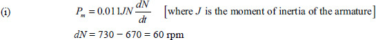
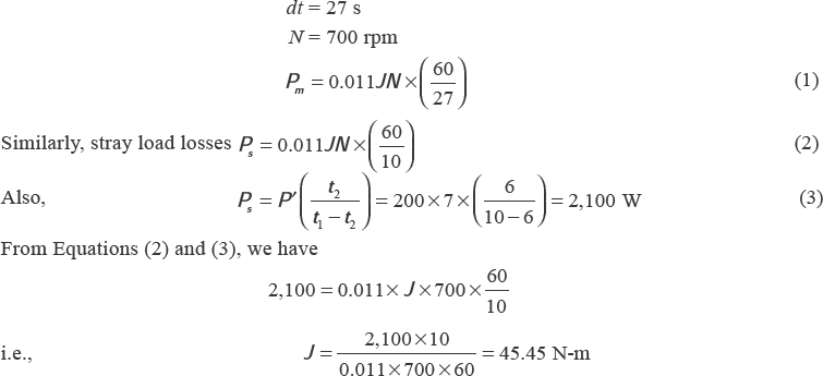
(ii) Dividing Equation (1) by Equation (2), we have
5.29 FIELD’S TEST
Small series motors can be tested by the brake test, while large series motors cannot be tested by this method. Field’s test is applicable to two similar series machines, which are used for traction purposes. Figure 5.35 shows field’s test on series machines.
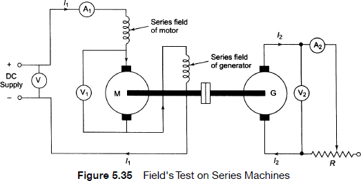
Figure 5.35 shows two machines, which are mechanically coupled together and their series fields are connected in series to make the iron losses of both the machines equal. One machine runs as a motor and drives the generator whose output is wasted in variable load R. R is varied until the ammeter A1 shows the full-load current of the motor. The readings of the following instruments are taken:
- voltmeter V (supply voltage),
- voltmeter V1(terminal voltage of motor),
- ammeter A1(motor input current),
- voltmeter V2(terminal voltage of generator) and
- ammeter A2(load current of generator).
Let R and R be the armature resistance and field resistance of each machine.
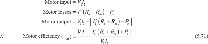
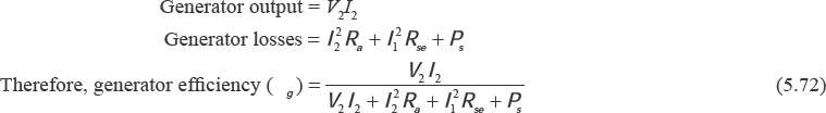
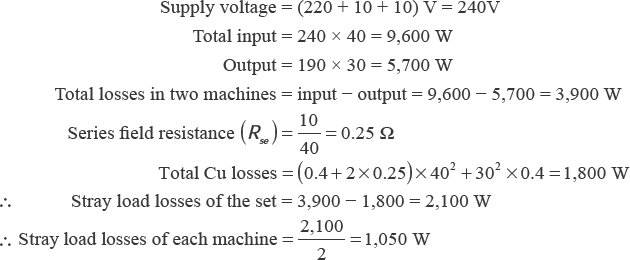
Input to the whole set = VtI1, output = V2I2, total losses of the set (Pt) = Vt I1 −V2I2, armature and field Cu loss of the motor = I21 (Ra + Rse), armature and field Cu-loss of the generator = I22 Ra + I21 Rse, total Cu loss of the set (Pc) = I21 (Ra + Rse) + I22 Rse + I21 Rse = I21 Rse = I21 (Ra + 2Rse) + I22Ra, stray load losses = Pt –Pc.
![]()
Motor efficiency
Generator efficiency
Example 5.24 During the field test on two mechanically coupled similar DC series machines(with their fields connected in series and with one machine as a motor and the other as a generator), the following data are obtained:
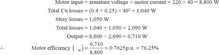
Motor:
Armature current = 40 A
Armature voltage = 220 V
Voltage drop across its field windings = 10 V
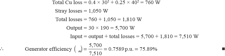
Generator:
Armature current = 30 A
Armature voltage = 190 V
Voltage drop across its field windings = 10 V
Calculate the efficiency of each machine. Take armature resistance of each machine as 0.4 Ω.
Motor efficiency
Generator efficiency
5.30 USES OF DC MOTORS
The shunt motor has fairly constant speed as well as medium starting torque. It has the following applications:
- blowers and fans,
- lathe machines,
- centrifugal and reciprocating pumps,
- machine tools,
- milling machines and
- drilling machines.
The series motor has variable speed and high starting torque. No-load speed is dangerous. It has the following applications:
- cranes,
- trolleys,
- hoists and elevators,
- conveyers and
- electric locomotives.
Cumulative compound motor has high starting torque, and no-load condition is allowed. It has the following applications:
- punches,
- rolling mills,
- shears,
- elevators and
- heavy planers.
The speed of differential motor increases with load and hence these motors are not suitable for practical applications.
5.31 SPECIAL DC MACHINES
Special DC machines such as three-wire generators, dynamometers and some cross-field machines are discussed.
5.31.1 Three-wire Generator
A three-wire generator is used to get low and high voltages. Figure 5.36 shows a three-wire DC generator having two poles and ring winding. It has two outer wires and one neutral wire. An induction coil D is wound on the iron core, which is connected between two coils having one-pole pitch apart. The frequency of the induced AC voltage in the coil is of ![]() . The coil has high reactance and hence the current drawn by the coil is very low. The middle of the coil is connected to the neutral so that the three-wire DC system is formed. If the currents in the outer wires areequal, and the neutral will carry no current. The voltage between outer wires is twice that of the value between the outer and the neutral wires.
. The coil has high reactance and hence the current drawn by the coil is very low. The middle of the coil is connected to the neutral so that the three-wire DC system is formed. If the currents in the outer wires areequal, and the neutral will carry no current. The voltage between outer wires is twice that of the value between the outer and the neutral wires.
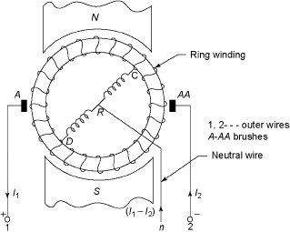
Figure 5.36 A Three-wire DC Generator
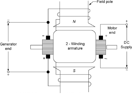
Figure 5.37 Dynamometer
5.31.2 Dynamometer
A dynamometer is a motor and generator unit assembled in the same unit where the armature core and pole pitch structure are common. Figure 5.37 shows a dynamometer. It has separate armature and commutator with brush gear for the generator motor. When machine is impressed, it runs as a motor. Other armature gets emf and acts as a generator due to common field flux. The emf of the generator can be controlled by varying the number of conductors in the armature. To control the generator voltage, the supply voltage is varied. The efficiency of the set is very high and is commonly used in radio and communication systems. The motor is generally driven by the battery. The output voltage of the generator can be 1,000 to 1,500 V.
5.31.3 Cross-field Machines
Cross-field machines are also called rotating amplifi ers, which are DC machines with additional brush set along the α-axis. Figure 5.38 shows a DC generator. The output power is controlled by varying the field current of the generator. If P2 is the output power and P1 is the input power to the field winding, the power amplification becomes ![]() . The input power is usually 1 per cent of output power and hence
. The input power is usually 1 per cent of output power and hence ![]() ≅ 100. There is a power amplifi cation in the DC generator. Since it is rotating, the rotating amplifier is derived. Depending on the degree of compensation, the cross-field generators can be classified as (i) metadyne and (ii) amplidyne.
≅ 100. There is a power amplifi cation in the DC generator. Since it is rotating, the rotating amplifier is derived. Depending on the degree of compensation, the cross-field generators can be classified as (i) metadyne and (ii) amplidyne.
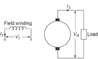
Figure 5.38 DC Generator
5.31.3.1 Metadyne
Figure 5.39 shows a metadyne generator, which is obtained from an ordinary DC generator by providing an additional pair of brushes in the d-axis whereas the brushes in the q-axis are short circuited. The current (Iq) in the q-axis produces an mmf Mq along the q-axis, which is the first stage of amplification. The voltage induced along the q-axis due to controlled mmf Mf circulates Iq when the brushes are short circuited. In the second stage, due to rotation of armature in the mmf Mq, a voltage is developed along the d-axis across which the load is connected. Due to the current Id, the armature mmf in the d-axis opposes the control mmf Mf according to Lenz’s law. Iq and Id attain a steady-state value for a given value of If and load resistance. If there is any increase in the value of Id, it will increase Md that neutralizes Mf Hence, the induced emf along the d-axis is reduced that prevents further increase in current keeping the output current of a metadyne substantially constant over a wide range of load variation. Therefore, the metadyne is also called a constant current generator.
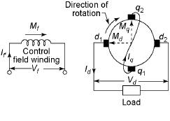
Figure 5.39 Metadyne Generator
5.31.3.2 Amplidyne
Figure 5.40 shows an amplidyne, which is a meta-dyne having a compensation for a d-axis mmf Md. In Figure 5.40, a compensating winding is provided on the stator to produce an mmf Mc opposing Md. Due to the flow of current through the compensating winding, the compensating mmf is produced and hence the negative feedback effect due to load current Id is minimized.
The flux along the d-axis depends solely on Mf due to the presence of the compensating winding. Since there are differences in space distribution between Md and Mq, it is difficult to achieve complete neutralization of Md. The ratio of effective turns of compensating winding to effective turns of the armature winding is called the compensating factor.
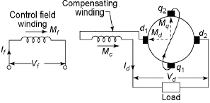
Figure 5.40 Amplidyne
5.32 CHARACTERISTICS OF CROSS-FIELD GENERATORS
To derive analytically the characteristics of the cross field-generator, let Tf be the effective turns of the control field winding, Td be the effective turns of the control armature along the d-axis, N be the speed of the generator in rpm and C be the compensation factor.
The net ampere turns on the d-axis is
![]()
The net ampere flux along the d-axis assuming no saturation is expressed by
![]()
The induced voltage along the q-axis
![]()
If Rq is the total resistance of the armature along the q-axis including the external resistance connected across the brushes q1q2, then

The flux along the q-axis is expressed by
![]()
where k4 is constant. The induced emf along the d-axis is expressed by
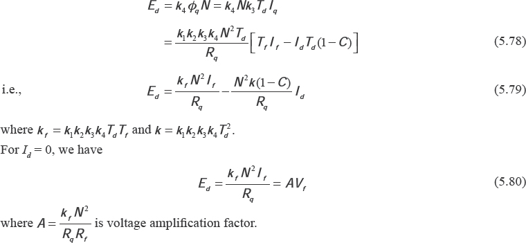
In general, Ed is expressed as
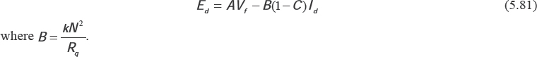
The terminal voltage of a cross-field generator is
![]()
where Rd = Ra + Rc is the resistance of the armature along the d-axis including compensating winding.

If RL is the load resistance, then
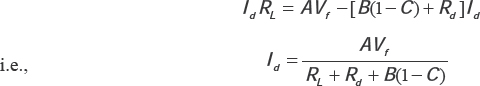
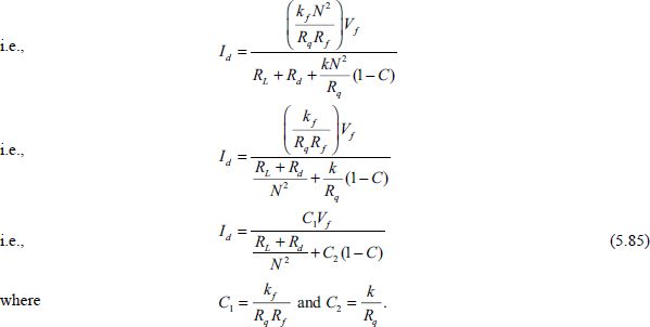
From Equation(5.85), Id increases with increase in speed, shown in Figure 5.41, which is the plot of load current versus speed. For an uncompensated cross-field generator, C = 0. In this case, the load current reaches a constant value for higher speeds. The polarity of the load current does not depend upon the direction of rotation of the generator. This is an important characteristic of the cross-field generator. Rosenberg generator used for battery charging and train lighting is an uncompensated cross-field generator whose output voltage is independent of the direction of motion of the train. Figure 5.42 shows the external characteristics of cross-field generators for different degrees of compensation. The terminal voltage is almost constant with load current for C = 1(i.e. 100 per cent compensation).
These cross-field generators are known as amplidynes. The output voltage remains constant and is more due to large magnification. For C = 0(i.e., zero compensation), the terminal voltage varies rapidly but the current remains constant as in metadyne generators. In addition to control and shunt field winding, series and shunt field windings are some times used to enhance the amplification. The interpoles for cross-field generators are placed along the q-axis and d-axis unlike DC generators. The required number of interpoles is twice that of main poles.
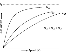
Figure 5.41 Plot of Id vs N
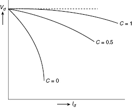
Figure 5.42 Plot of Vd vs N
5.33 BRUSHLESS DC MOTOR
The main difference between the brush-less DC motor and the ordinary DC motor is the type of commutator used. Mechanical commutation is done in the DC motor, whereas electrical commutation is done in the brushless DC motor. The construction of the brushless DC motor is similar to that of a permanent magnet synchronous motor. The rotor consists of the permanent magnet, whereas the polyphase winding is placed on the stator. The cross-sectional view of a brushless DC motor is shown in Figure 5.43
Due to the combination of drive, its electronic drive circuit and rotor position sensor, the word ‘brushless DC motor’ is used. The electronic drive circuit in the brushless DC motor is an inverter consists of the transistor, and it feeds stator winding, where the transistors are controlled by pulses generated by rotor position sensors ensuring that the rotor revolves at an angular speed. This angular speed is equal to the average speed of the field produced by the stator.
The driver circuit is fed by DC supply like DC motors where the fields of stator and rotor remain stationary with respect to each other at all the speeds. The torque speed characteristic is similar to the DC motor. The speed can be controlled by the DC supply voltage. Due to these similarities and without brush, this type of machine is known as brushless DC machine. The two types of brushless DC motors available in practice are(i) the unipolar or half-wave brushless DC motor and(ii) the bipolar or full-wave brushless DC motor
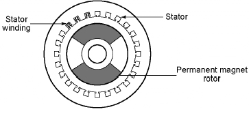
Figure 5.43 Cross-sectional View of a Brushless DC Motor
5.33.1 Unipolar or Half-wave Brushless DC Motor
In this type, optical sensors are embedded on the rotor to excite these sensors. Three phototransistors –P1, P2 and P3 – are mounted on the end plate of the motor separately by an angle of 120°. Figure 5.44 shows the arrangement of the optical sensor.
The armature consists of a polyphase winding(three-phase) mounted on the stator, and the field consists of a two-pole permanent magnet. The driving circuit consists of simple transistors Q1, Q2 and Q3, which are used to excite the stator winding. Figure 5.45 shows the schematic arrangement of the unipolar brushless DC motor.
The phototransistors get exposed to light due to the revolution of the shutter. For each revolution, the phototransistors generate the pulses PI1, PI2 and PI3. The duration and phase displacement of PI1, PI2 and PI3 are shown in Figure 5.46.
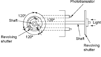
Figure 5.44 Arrangement of the Optical Sensor
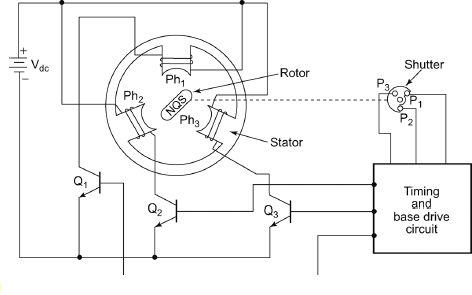
Figure 5.45 Schematic Arrangement of Unipolar Brushless DC Motor
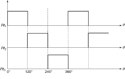
Figure 5.46 Pulses Generated by Phototransistors
The phototransistor (P1) generates a pulse when it receives light, and it generates pulse PI1. Hence, the transistor (Q1) gets turned on. Therefore, current flows through the phase winding Ph1 producing the north pole face of Ph1. The rotor revolves in the anticlockwise direction. The light stops falling on P1 due to the revolution of the rotor and P2 gets the light generating pulse Pl2. This turns on the transistor Q2. Therefore, current flows through Ph2 and it produces north pole face of Ph2. Rotor further rotates in the anticlockwise direction and it reaches the axis of the pole face Ph2 and light stops falling on P2. Now, the light starts to fall of P3 which in turn turns on the transistor Q3. Therefore, current flows through Ph3 and it produces the north pole face of Ph3. Switching sequence is repeated. Hence, the continuous rotation of the rotor is obtained.
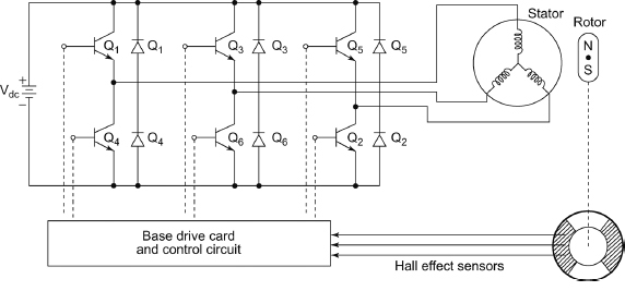
Figure 5.47 Bipolar Brushless DC Motor
To obtain the torque reversal, the operation of timing and base circuit drive circuit is carried out in such a way that the transistors Q1, Q2 and Q3 are carried out for the duration of pulses Pl2, Pl3 and Pl1 respectively. The base drive signals of the transistors are shifted by 180° to obtain the torque reversal. No feedback or free wheeling diode is required for small motors because the inductive energy in the phase windings is very small, which cannot cause any destruction to the transistors. The cost of the motor is very low and the drive circuit is very simple. The prime limitation of this motor is that it cannot be used above 100 W. The feedback diode is required when the stored energy in the phase winding inductance is large. The bipolar brushless DC motor is used in such cases.
5.33.2 Bipolar or Full-wave Brushless DC Motor
Figure 5.47 shows a bipolar brushless DC motor, which uses three-phase inverter with feedback diodes where the feedback diodes return the inductive energy to the supply. Hall effect sensors are used by rotors to sense the position where the hall effect sensors and magnet ring form the rotor position sensors. The magnet ring is mounted on the rotor shaft and the hall sensors are 120° electrical apart from each other.
The response rotor position sensor causes the switching of each transistor. The transistors are triggered in sequence Q1, Q2, Q3, Q4, Q5 and Q6 where each transistor conducts for 120°. At any time, two transistors conduct and each pair conducts for 60°. The phase shifting of the transistor base drive signals is done 180° to achieve the torque reversal. Since each phase conducts twice in a cycle and hence better utilization of stator takes place compared to the unipolar drive. The bipolar type is suitable for high-performance servo drives. These are also suited for the ratings higher than 100 W.
5.34 FEATURES OF BRUSHLESS DC MOTOR
The following are the features of the brushless DC motor compared to the conventional DC motor:
- These motors do not need maintenance practically due to the absence of commutator and brushes.
- Life is long.
- Highly reliable operation.
- Low inertia and friction.
- Operation is noiseless due to low radiofrequency interference and noise.
- Cooling is better because the armature winding is on the stator.
- Efficiency is as high as 75 to 80 per cent due to the feedback diodes.
ADDITIONAL SOLVED PROBLEMS
Example 5.25 A four-pole, 220 V, lap-connected DC series motor has 200 slots with six conductors per slot. The current is 40 A and flux/pole is 16 mWb. The armature and field resistances are 0.46 Ω and 0.26 Ω, respectively. The iron and friction losses are 700 W. Calculate the useful torque.
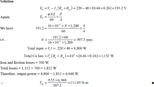
Example 5.26 The no-load and shunt field currents of a 240 V, four-pole, lap-connected DC shunt motor are 7 A and 2 A, respectively. Its full-load current and armature resistance are 90 A and 0.15 Ω, respectively. At no-load, the flux per pole is 0.06 Wb. The motor has 700 conductors and contact drop per brush is 1 V Determine(i) no-load speed, (ii) full-load speed and(iii) speed regulation. Field flux is reduced by 2 per cent due to armature reaction.
At no-load

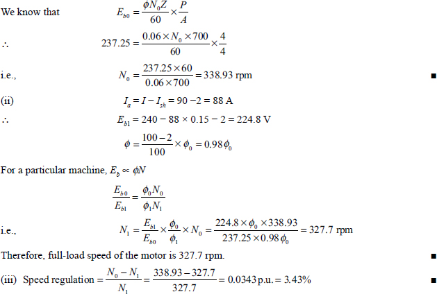
Example 5.27 The line current and speed of a 220 V DC shunt motor are 55 A and 700 rpm, respectively. The armature and field resistances are 0.14 Ω and 110 Ω, respectively. Considering 1 V/brush as contact drop, calculate (i) the no-load speed if no-load current is 7 A and (ii) the percentage reduction in the flux per pole so that the speed becomes 900 rpm at armature current of 35 A. Neglect the effect of armature reaction.
Solution
(i) At no-load
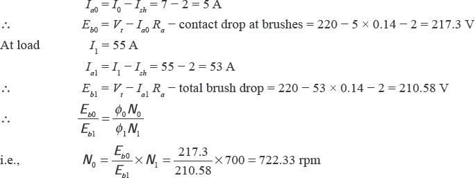
Therefore, no-load speed of the motor is 722.33 rpm.
(ii) Let the flux be φ2 at a speed of 900 rpm at armature current of 35 A.
Eb2 = V1 – Ia2 Ra – total brush drop = 220 – 35 – 0.14 – 2 = 213.1 V
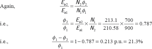
Therefore, the required percentage reduction in flux is 21.3 per cent.
Example 5.28 A 240 V DC shunt motor takes a full-load current of 60 A. Its armature and shunt field resistances are 0.25 Ω and 120 Ω, respectively. The motor draws a current of 6 A at no-load having a speed of 1,000 rpm. Determine (i) full-load speed, (ii) speed regulation, (iii) HP (British) rating of the machine and (iv) full-load efficiency.
Solution
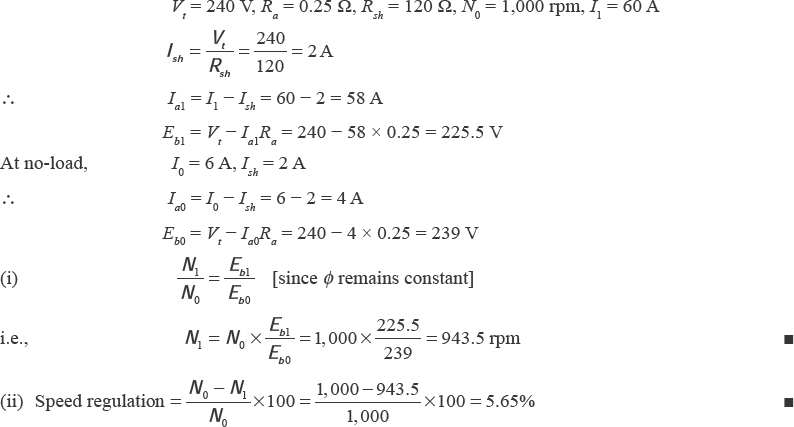
(iii) Full-load power output = full-load power developed - stray losses
= Eb1Ia1 – stray losses
Stray losses = mechanical power developed at no-load = Eb0Ia0
This is because the entire power developed is used to overcome stray losses at no-load.
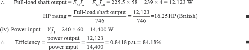
Example 5.29 A four-pole, 240 V, wave-connected DC shunt motor has 1,000 conductors, and useful flux/pole is 8 mWb. Armature and field resistances are 0.4 Ω and 240 Ω, respectively. If the motor draws a current of 25 A from the supply mains, find the speed and torque developed by the motor. If magnetic and mechanical losses are 800 W, find (i) useful flux and (ii) efficiency at this load.
Solution
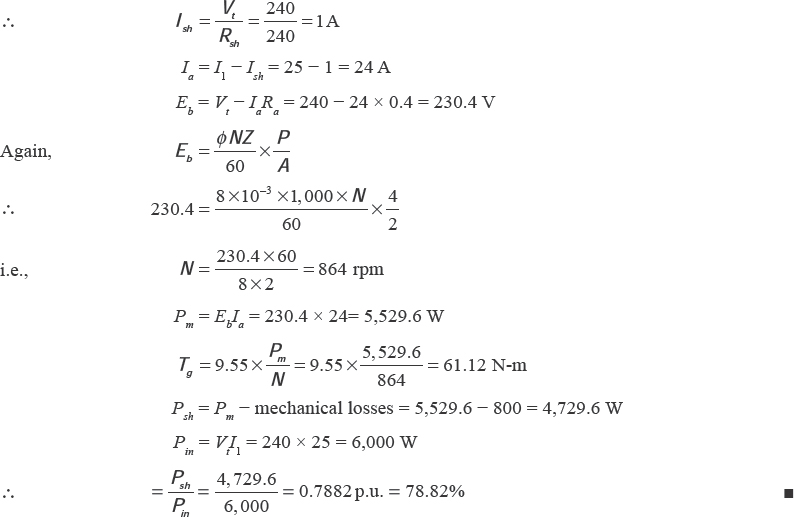
Example 5.30 A 240 V, 7,355 W, DC shunt motor has armature and field resistances of 0.5 Ω and 120 Ω, respectively. The motor runs at a speed of 1,000 rpm on full-load having full-load efficiency of 88 per cent. If the speed is to be raised to 1,200 rpm keeping the load constant, find the extra resistances to be added in the field circuit.
Solution
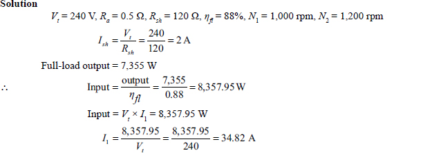
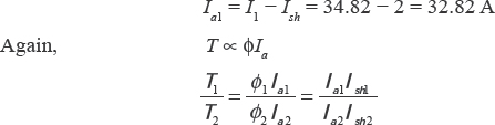
Since load torque remains constant, we have
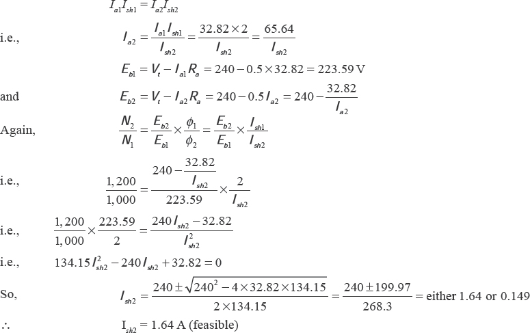
Let the resistance R be connected in series with the field circuit.
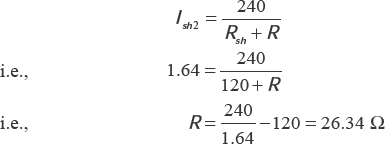
Therefore, the required resistance is 26.34 Ω.
Example 5.31 A 240 V DC shunt motor develops an output of 20 kW when it takes 23 kW. The armature and field resistances are 0.2 Ω and 125 Ω, respectively. Find the efficiency and power input when output is 12 kW. Assume stray and friction losses remain constant.
Solution
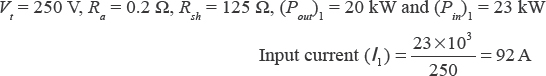
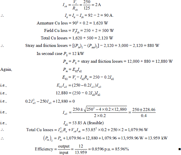
Example 5.32 A 240 V DC shunt motor takes a current of4 A from 240 V supply mains while running at no-load. The armature and field resistances are 0.2 Ω and 240 Ω, respectively. Determine (i) the efficiency of the motor when it draws 20 A from the supply mains, (ii) the armature current during maximum efficiency and (iii) the value of maximum efficiency.
Solution
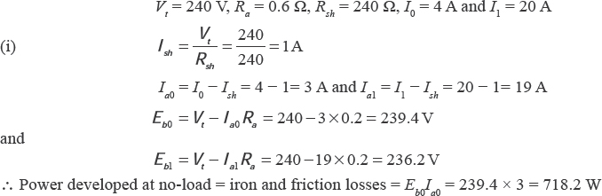
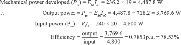
(ii) For maximum efficiency,
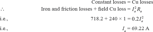
The armature current at maximum efficiency is 69.22 A.
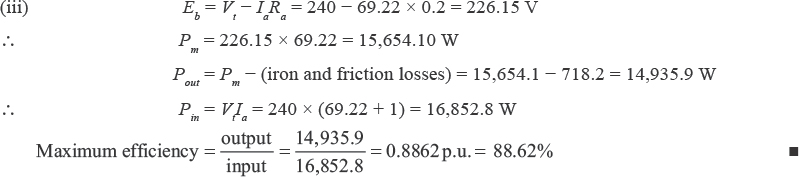
Example 5.33 A 230 V DC shunt motor takes an armature current of 3.40 A at rated voltage and at no-load speed of 1,000 rpm. The armature and field circuit resistances are 0.4 Ω and 170 Ω, respectively. The line current at full-load and rated voltage is 41 A. Calculate (i) the speed at full-load and the developed torque in case the armature reaction weakens the no-load flux by 4 per cent, (ii) the shaft power if rotational losses at no-load and full-load are the same and (iii) the efficiency of the motor for case (ii).
Solution
(i) The back emf at no-load is given by
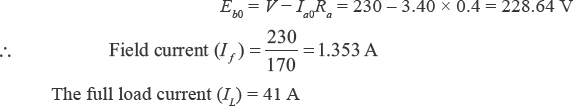
During full-load, the armature current is given by
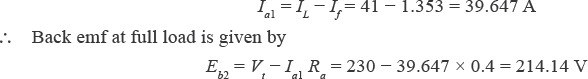
At full load, the field flux is given by
φ1 = 0.96 φ0
where φ1 is the flux at no-load.
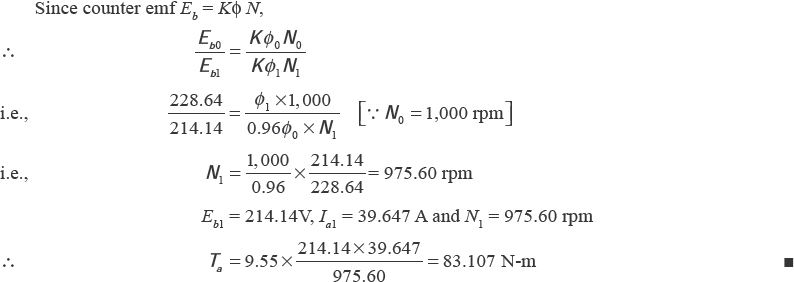
(ii) Rotational losses (Pr) = Eb0 Ia0 = 228.64 – 3.40 = 777.376 W
∴ Shaft power (Psh) = electromagnetic power – rotational losses
Since electromagnetic power or mechanical power (Pm)
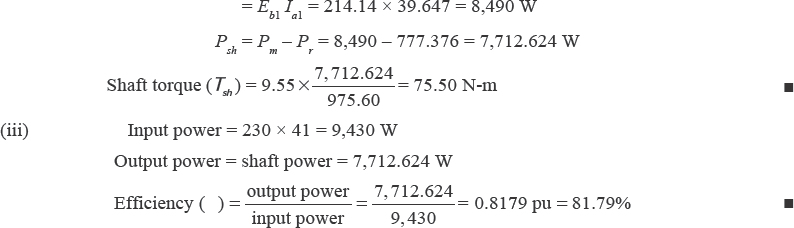
Example 5.34 A 240 V DC shunt motor takes 26 A at rated voltage and runs at 1,000 rpm. Its field resistance is 120 Ω and armature circuit resistance (including brushes) is 0.25 Ω. Compute the value of additional resistance required in the armature circuit to reduce the speed to 900 rpm, when (i) the load torque is independent of speed, (ii) the load torque is proportional to speed and (iii) the load torque varies as square of the speed.
Solution
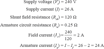
Here, the speed is to be reduced from 1,000 rpm to 900 rpm without disturbing the shunt fi eld current. So the fi eld flux (φ) remains constant.
(i) The load torque is independent of speed. Therefore, the electromagnetic torque remains constant at both speeds.
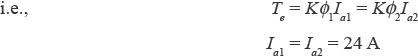
At 1,000 rpm, the back emf
![]()
At 900 rpm, the back emf
![]()
where R is the additional resistance connected in series with armature.
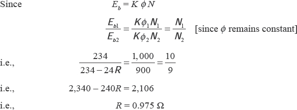
The required additional resistance is 0.975 Ω.
(ii) In this case, TL ∝ N
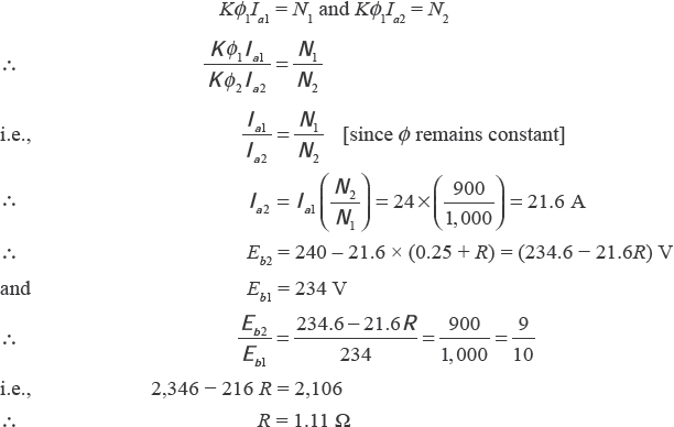
The required additional resistance is 1.11 Ω.
![]()
Similarly from part (ii), we have
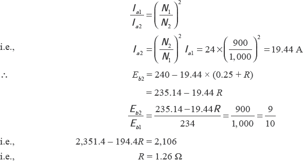
The required additional resistance is 1.26 Ω.
Example 5.35 A DC series motor running a fan at 1,000 rpm takes 50 A from 240 V mains. The armature plus field resistance is 0.4 Ω. If an additional resistance of 4.6 Ω is inserted in series with the armature circuit, determine the motor speed in case the field flux is proportional to the armature current. Assume the load torque for a fan is proportional to the square of the speed.
Solution
The load torque (TL) is given by
![]()
The mechanical torque (Tm) is given by
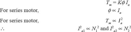
where Ia1 is the armature current when N1 = 1,000 rpm.
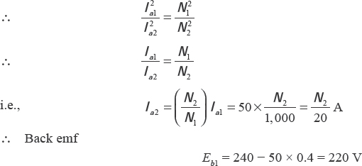

Example 5.36 A 10 kW, 240 V, DC shunt motor draws a line current of 5.2 A while running at noload speed of 1,200 rpm from a 240 V DC supply. It has an armature resistance of 0.25 Ω and a field resistance of 160 Ω. Determine the efficiency of the motor when it delivers the rated load.
Solution
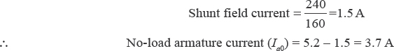
Constant no-load rotation loss (W) is given by
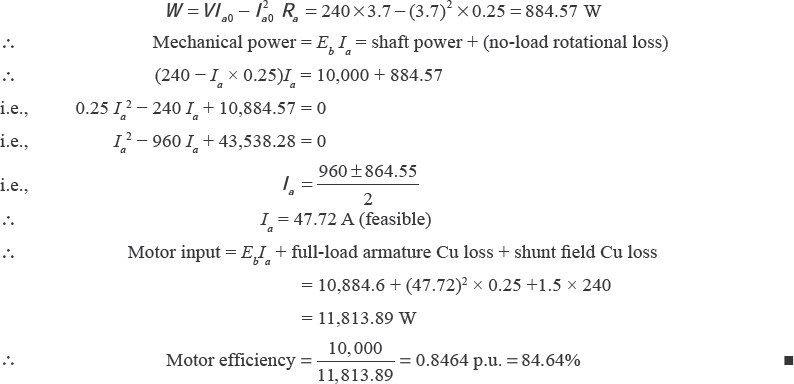
Example 5.37 A 440 V DC shunt motor has a no-load speed of 2,000 rpm. It is running at 1,000 rpm at full-load torque. Its load torque is reduced to 50 per cent of rated value with armature voltage and field voltage held constant at previous values; the speed increases to 1,050 rpm. Find the armature voltage drop at full-load. Neglect the effect of armature reaction.
Solution
Let the armature current at full-load torque be Ia1.
∴ Back emf (Eb1) at full-load torque is given by
Eb1 = (440 – Ia Ra) ∝ N1f1
∴ Motor torque, Tm1 = Kφ1Ia1 and Tm2 = Kφ2Ia2
Since the fi eld voltage is held constant, we have φ2 = φ1
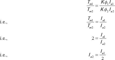
∴ Counter emf (Eb2) at half the rated torque is given by
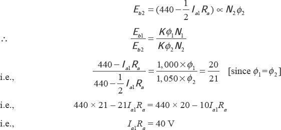
Armature voltage drop at full-load = Ia1 Ra = 40 V.
Example 5.38 A 220 V, 1.5 kW, 859 rpm, separately excited DC motor has armature resistance of 2.5 Ω and it draws a current of 8 A at rated load condition. If the field current and the armature current are fixed at the value of rated speed at rated load, what will be the no-load speed of the motor? Assume losses remain constant between no-load and full-load operations.
Solution
Let Eb1 and Eb0 be the back emf at rated load and no load, respectively. During no-load, Ia0 = 0, and at rated load, Ia1 = 8 A (given)
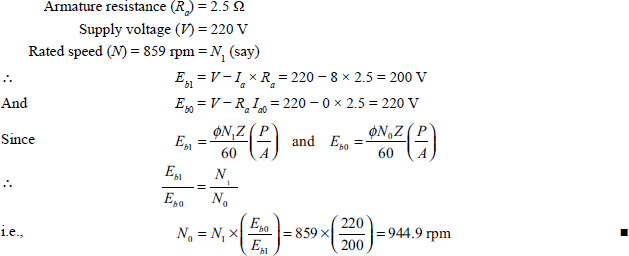
Example 5.39 A 220 V DC shunt motor develops a total torque of 90 N-m and draws a current of 27 A from supply mains and runs at 700 rpm. The armature and shunt field resistances are 0.2 Ω and 110 Ω, respectively. Determine the percentage reduction of the field flux and the additional resistance to be inserted in series with the field circuit if the speed is to be increased to 900 rpm. The gross torque at 900 rpm is 75 N-m. Assume that magnetization characteristic is a straight line and neglect the armature reaction.
Solution
Vt = 220 V, Ra = 0.2 Ω , Rsh = 110 Ω, N1 = 700 rpm, N2 = 900 rpm, Ta1 = 90 N-m and Ta2 = 70 N-m, I1 = 27 A
Let φ1 and φ2 be the fluxes when the speeds are 700 rpm and 900 rpm, respectively.
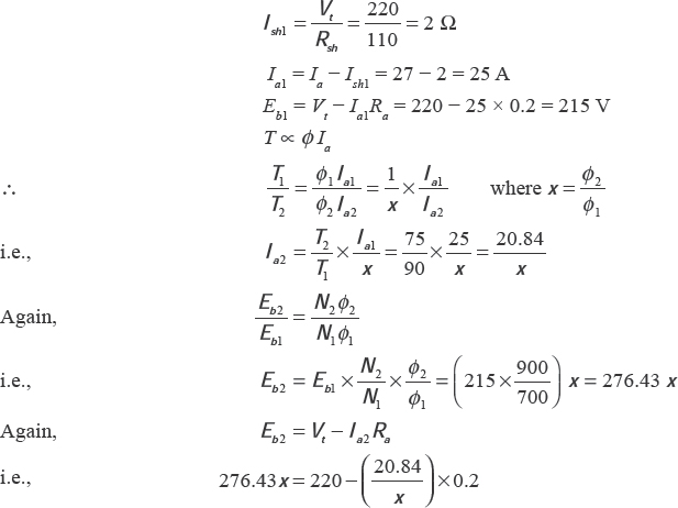
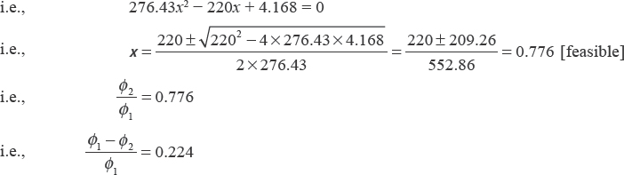
Therefore, percentage reduction of flux is 22.4 per cent.
Since the magnetization characteristic is linear, we have
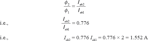
If R is the additional resistance to be inserted in series with the field coil, we have
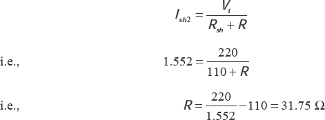
Therefore, a resistance of 31.75 Ω is required to be inserted in series with the field coil.
Example 5.40 A 400 V DC shunt motor drives a load and takes 25 A from supply mains running at a constant speed. The load torque varies with the square of the speed. If a resistance of 15 Ω is inserted in series with the armature, determine the new speed as a percentage of the original speed. Shunt field resistance of the motor is 200 Ω. Neglect armature resistance.
Solution
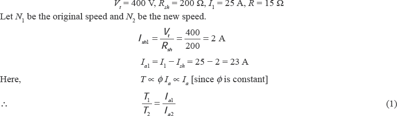
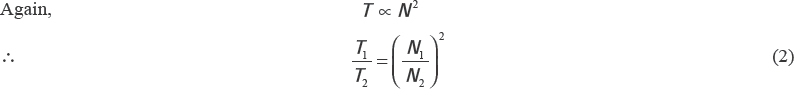
From Equations (1) and (2), we have
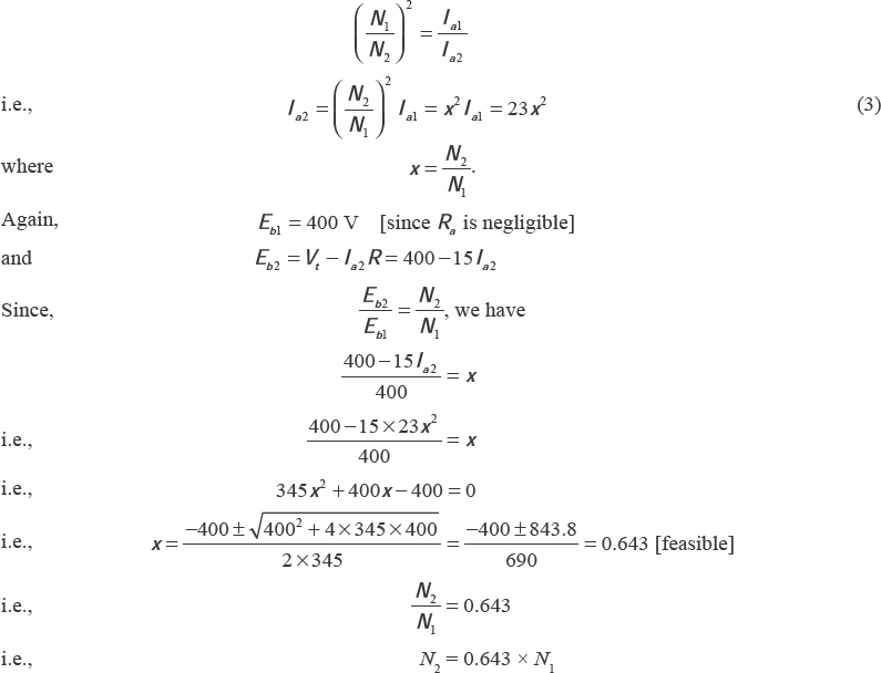
Hence, new speed is 64.3 per cent of original speed.
Example 5.41 A 240 V DC shunt motor draws a current of 50 A from supply mains at full-load while running at a speed of 1,000 rpm. It delivers 10.5 kW at full-load. The armature and shunt field resistances are 0.2 Ω and 240 Ω, respectively. If a resistor is to be inserted in series with the armature to reduce the speed to 0.85 times of the full-load speed, determine the resistance of the resistor and efficiency at this speed. The constant loss varies as (speed)13. Assume that field and armature currents remain constant.
Solution
Vt = 240 V, Pout = 10.5 kW, I1 = 50 A, N1 = 1,000 rpm, Ra = 0.2 Ω, Rsh = 240 Ω
Power input (Pin) = VtI1 = 240 – 50 = 12,000 W
Total losses on full-load = Pin – Pout = 1.5 kW
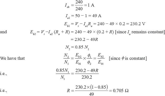
Full-load armature Cu loss = I2aRa = 492 – 0.2 = 480.2 Ω
Shunt field Cu loss = VtIsh = 240 – 1= 240 W
Total full-load Cu loss = 480.2 + 240 = 720.2 W
Therefore, constant losses at full-load = 1,500 – 720.2 = 779.8 W
∴ Constant losses at 0.85 times of full-load = (0.85)2 × 779.8 = 631.28 W

Example 5.42 The full-load rating of a 250 V DC shunt motor running at 1,000 rpm is 10 kW. The armature and shunt field resistances are 0.5 Ω and 250 Ω, respectively. The full-load efficiency is 90 per cent. Calculate the following:
(i) no-load current,
(ii) speed when the motor takes 25 A and
(iii) the armature current when the torque produced is 90 N-m and speed 900 rpm.
Solution
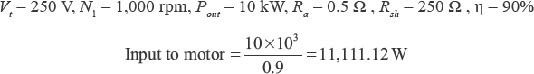
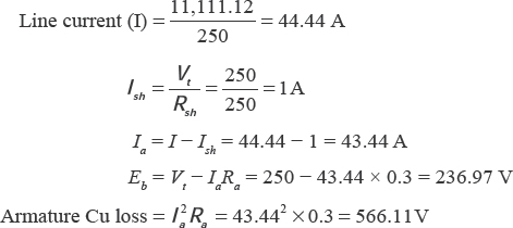
Therefore, constant losses = total losses – armature Cu losses = (input – output) – 566.11
= (11,111.12 – 10,000) – 566.11 = 545 W
Neglecting armature Cu loss at no-load, the no-load input = 545 W.
![]()
(ii) Back emf when line current is 25 A is given by
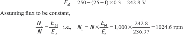
(iii) Let the armature current be Ia2 for Ta2 = 90 N-m and speed N2 = 900 rpm
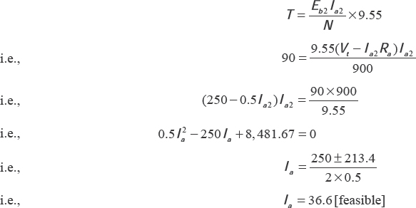
Example 5.43 A 240 V DC shunt motor has armature resistance of 0.40 Ω. The maximum current limit is to be 65 A and the minimum is three-fourths of this value. Find the number of sections of the starter and calculate the resistance of each element.
Solution
![]()
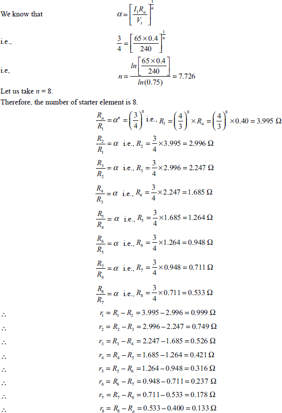
Example 5.44 Calculate the values of the five steps in a six-stud starter for a5HP (metric), 220 V, shunt motor having full-load efficiency of 89 per cent. The current is not to exceed twice the full-load current. Armature Cu loss is half the total loss. Field current is 0.62 A.
Solution
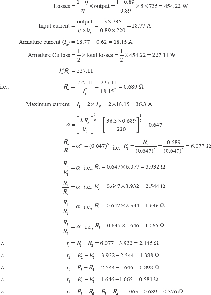
Example 5.45 A 20 HP, 500 V, DC shunt motor having efficiency of 88 per cent at rated load is required to reach 1,000 rpm in 30 seconds from rest against full-load torque. The armature and field resistances of the motor are 0.33 Ω and 250 Ω, respectively. The moment of inertia of the moving part is 13.85 kg-m2. A starter is required to design having capability to limit the maximum line current to 52 A. Assume that the average current during the staring period is equal to the mean of the minimum and maximum current.
Solution
Let J be the moment of inertia of the system in kg2m and ω be the angular velocity in rad/second.
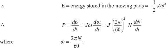
Let Ia be the current in excess for acceleration.
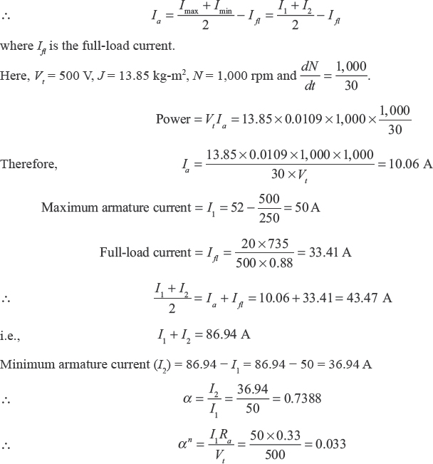
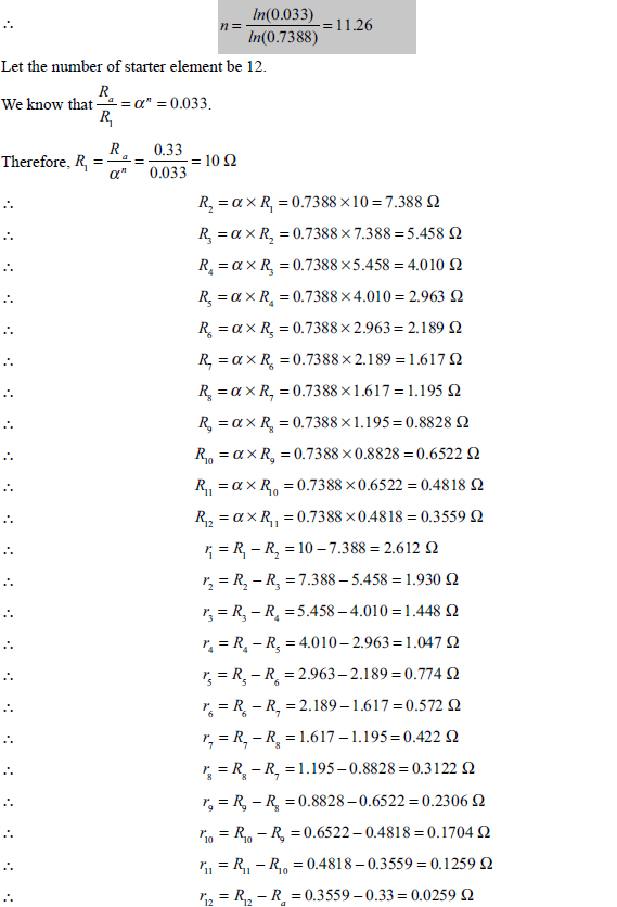
SIGNIFICANT POINTS
Shunt Motor:
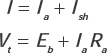
Series Motor:
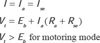
The electrical power input = VtIa
The gross mechanical power developed in the armature (Pm) = EbIa
Back emf:
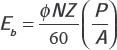
Armature Torque:
SHORT QUESTIONS AND ANSWERES
Q.1What do you mean by a DC motor?
Ans. It is a DC machine, which converts electrical energy into mechanical energy.
Q.2 What is the working principle of a DC motor?
Ans. If a current-carrying conductor is placed in a magnetic field, a force is exerted on the conductor. The direction of force acting on the conductor is determined by Fleming’s left-hand rule. This is the working principle of a DC motor.
Q.3 What are the types of DC motors?
Ans. (i) Series wound, (ii) shunt wound and (iii) compound wound.
Q.4 What will be the armature current in a DC motor?
Ans. Let Vt be the applied voltage and Eb be the back emf. Then the effective emf acting around the armature circuits is ![]() . Therefore, the armature current
. Therefore, the armature current ![]() where is Ra the armature resistance.
where is Ra the armature resistance.
Q.5 What is mechanical power in a DC motor?
Ans. Mechanical power ![]() where
where![]() represents power in watt supplied to the armature and Ia2Ra is the armature copper loss in watt.
represents power in watt supplied to the armature and Ia2Ra is the armature copper loss in watt.
Q.6 What is the condition for maximum power?
Ans. The condition for maximum power is ![]()
Q.7 Where is torque maximum?
Ans. Torque is maximum when it is at right angles to the magnetic flux.
Q.8 What is the torque relation in a DC motor?
Ans.The toque in DC motor is proportional to the flux per pole and the armature current, that is, ![]() .
.
Q.9What are the losses in a DC motor?
Ans. The losses in a DC motor are as follows
- (a) Copper losses
- (i) Armature copper losses (Ia2Ra)
- (ii) Field copper losses (Ish2Rsh)
- (iii) Loss due to brush contact resistance (EbIa), where Eb is the drop due to brush resistance)
- (b) Magnetic losses occur in the core of the motor
- (i) Hysteresis loss
- (ii) Eddy current loss
- (c) Mechanical losses
- (i) Windage loss due to rotating armature
- (ii) Frictional loss at the bearings
- (iii) Frictional loss due to brush contacts
Mechanical losses and magnetic losses are termed as stray losses (W1). Stray losses and shunt field copper losses are known as constant losses.
Q.10 What do you mean by the commercial efficiency of a DC motor?
Ans. The commercial or overall efficiency of a DC motor,
![]()
Q.11 What is the condition for maximum efficiency in a DC motor?
Ans.The condition for maximum efficiency in a DC motor is that copper losses are equal to constant losses.
Q.12 What is the speed relation in a DC motor?
Ans. The speed of a DC motor is directly proportional to the back emf and inversely proportional to the flux pole:
![]()
Q.13 What will be the result if the field circuit of a DC motor is opened?
Ans. Due to weakening of field flux, the armature will race up to abnormally high speeds, and due to the severe centrifugal forces, the armature windings may get permanently damaged.
Q.14 What is meant by speed regulation of a DC motor?
Ans. Speed regulation of a DC motor is defined as the change in speed when the load on the motor is reduced from rated load to zero and is expressed in percentage of the rated load speed.
![]()
Q.15 What are the characteristics of a DC motor?
Ans. There are two main characteristics: electrical and mechanical characteristics.
- (a) Electrical characteristics are
- (i) speed (N) versus armature current (Ia) and
- (ii) torque (T) versus armature current (Ia).
- (b) Mechanical characteristic is torque (T) versus speed (N).
Q.16 Why does a shunt motor run at a constant speed?
Ans. We know that ![]() . As the shunt field resistance is constant, the shunt field current is constant. Accordingly, the flux per pole is practically constant. The back emf is also practically constant. Hence, by speed relation, it is seen that the speed of a DC shunt motor is constant.
. As the shunt field resistance is constant, the shunt field current is constant. Accordingly, the flux per pole is practically constant. The back emf is also practically constant. Hence, by speed relation, it is seen that the speed of a DC shunt motor is constant.
Q.17 Why is the speed of a DC shunt motor dependent on back emf only?
Ans. The speed of a DC shunt motor is dependent on back emf because the flux is practically constant in a DC shunt motor.
Q.18 What are the characteristics of a DC shunt motor?
Ans. (i) The starting torque is poor.
(ii) The speed of the shunt motor is constant.
Q.19 What are the uses of a DC shunt motor?
Ans. Due to constant speed operation, DC shunt motors are used for driving line shaft, machine tools, lathe, wood working machines, milling machine, weaving machine, small printing press and so on.
Q.20 What do you mean by a DC series motor?
Ans. A DC motor in which the field winding is connected in series with the armature winding is known as a DC series motor.
Q.21 What are the characteristics of a DC series motor?
Ans.(i) Starting torque is very high.
(ii) Speed decreases when the load increases.
(iii) Without load it runs at dangerously high speed.
Q.22 What will be the speed of a DC series motor at no-load?
Ans. The speed of a DC series motor at no-load is infinity.
Q.23 Why does a DC series motor run at a dangerous speed without load?
Ans. In a DC series motor, ![]() . When load is removed, the armature current as well as the field flux becomes very small and at the same time the back emf increases. According to the speed relation, the motor overruns and attains a dangerously high speed.
. When load is removed, the armature current as well as the field flux becomes very small and at the same time the back emf increases. According to the speed relation, the motor overruns and attains a dangerously high speed.
Q.24 Which type of DC motor has high starting torque but the poorest speed regulation for the same horsepower rating and full-load speed?
Ans. A DC series motor.
Q.25 What do you mean by a DC compound motor?
Ans. The DC motor in which a part of the field winding is connected in series with the armature winding and the other part of the field winding is connected in parallel with the armature winding is known as a DC compound motor.
Q.26 What are the advantages of a DC compound motor?
Ans. The DC compound motor can be operated as a series motor or shunt motor and the speed can be increased or decreased to a greater extent from the normal speed.
Q.27 What are the characteristics of a cumulative compound motor?
Ans. The characteristics of cumulative compound motor lie between those of shunt and series motors. The series field provides a high starting torque and the shunt field prevents overrunning in no-load condition.
Q.28 Where are cumulative compound motors used?
Ans. These motors are used for drives where high starting torque is required with the probability of the load being totally removed such as punch, press, shears, planning machine, conveyors, crushers, bulldozers, lift haulage gears, mine hoist, power fans, rolling mills, stamping press and large printing press.
Q.29 What do you mean by a differential compound motor?
Ans. The compound motor in which the series field winding and the shunt field windings oppose each other, acting in the reverse direction for the production of magnetism, is known as a differential compound motor.
Q.30 If a cumulative compound long-shunt generator is operated as a motor, what type of motor would it be?
Ans. It would be a differential compound long-shunt motor.
Q.31 What is brake test and where is the test used?
Ans. Brake test is a direct method of testing a DC machine in which the machine is actually loaded by applying some brakes to a water-cooled pulley mounted on the motor shaft. The brake band is fixed with the help of wooden blocks gripping the pulley. One end of the band is fixed to the floor via a spring balance and the other end is connected to a suspended weight. This method of testing can be used for small motors only because in a large machine it is difficult to dissipate the amount of heat developed at the brake.
Q.32 What is Swinburne’s test and where is this test used?
Ans. Swinburne’s test is the simplest indirect method of testing a DC machine without actually loading it, in which only losses are measured separately. From this knowledge, efficiency at any load can be predetermined only by calculation. This test can only be applied to shunt and compound machines where the field flux is practically constant by running at the machine at light load as a motor at its rated voltage.
Q.33 Is Swinburne’s test applicable to series motors? Give reason for your answer.
Ans. No, because a series motor cannot be run at no-load.
Q.34 How can you determine windage and friction losses of a DC shunt motor?
Ans. Running at no-load with normal voltage, the terminal voltage is reduced gradually till the motor stops. Multiplication of the voltage and the current obtained in this condition will be the windage and friction loss in watts.
Q.35 What is Hopkinson’s test and where is it applied?
Ans. Hopkinson’s test, also known as back-to-back test, is a regenerative method of testing in which two identical DC machines are mechanically coupled and electrically adjusted so that one of them acts as a motor and the other as a generator. The electrical power developed by the generator is utilized in driving the motor, while the mechanical power of the motor is supplied to drive the generator. Under this test, the electrical power will be required from the supply mains just to overcome the internal losses of the two machines. In this method, two identical machines of any size can be tested under full-load condition.
This method is applied for testing large machines on full-load condition for longer duration.
Q.36 What are the factors which control the speed of a DC motor?
Ans. Speed control depends upon the following factors:
- (i) voltage control,
- (ii) field flux control and
- (iii) armature current control.
Q.37 What is field control?
Ans. Field control is a method of controlling speed of a DC shunt motor above normal by regulating the field flux by means of a field regulating variable resistor connected in series with the field winding.
Q.38 What types of resistances are employed in armature circuit and field circuit for speed control?
Ans. A resistance of low ohmic value and high current-carrying capacity is employed in armature circuit, whereas a resistance of high ohmic value and low current-carrying capacity is employed in field circuit.
Q.39 What is meant by Ward-Leonard method of speed control?
Ans. Ward-Leonard method is the basic adjustable armature voltage control method of controlling speed of a DC shunt motor over the whole range from zero to normal speed in both directions, accomplished by means of an adjustable voltage generator.
Q.40 Where is Ward-Leonard method employed?
Ans. Ward-Leonard method of speed control is employed where fine speed adjustment and smooth acceleration are required, as in driving rolling mills, ship propulsion, colliery winders and elevators in both directions.
Q.41 What are the methods of speed control of a DC series motor?
Ans. The speed of a DC series motor can be controlled by the following methods:
- (a) Flux control method
- (i) By field diverters,
- (ii) armature diverters
- (iii) tapped field control and
- (iv) paralleling field coils
- (b) Variable resistance in series with the motor
Q.42 What do you understand by the field diverter?
Ans. It is a variable resistance of low ohmic value and high current-carrying capacity connected in parallel to the field winding.
Q.43 What is the difference between resistances used for field control method in shunt and series motors?
Ans. The resistance used for the shunt motor is of high ohmic value and low current-carrying capacity, whereas the resistance used for the series motor is of low ohmic value and high current-carrying capacity.
Q.44 What are the functions of a starter?
Ans. The functions of a starter are:
- (a) to limit the starting current,
- (b) to protect the motor from taking overload current,
- (c) to protect the motor against supply failure and
- (d) to facilitate the starting and stopping of the motor.
Q.45 What is the difference between a starter and a regulator?
Ans. Both the starter and regulator consist of resistances, the value of which is comparatively greater in the regulator. The starter resistance is connected in series with the armature resistance to limit the starting current, while the regulator is connected in series with the field winding to control the speed of the motor. The regulator consists of only resistance, but the starter consists of one no-volt release and one overload release in addition to starting resistance. A regulator has two terminals, whereas a starter has three or four terminals.
Q.46 Why are small motors connected directly to supply lines without starters?
Ans. The reasons are as follows:
- (i) Small motors have relatively higher armature resistance than large motors. So their starting current is not very high.
- (ii) They speed up quickly due to low moment of inertia.
- (iii) The momentary large starting current does not disturb the voltage regulation of supply lines.
Q.47 What are the types of starters used in DC shunt and compound motors?
Ans. The two types are:
- (i) three-point face plate box-type starter and
- (ii) four-point face plate box-type starter.
Q.48 Why is the no-volt release coil of a three-point starter connected in series with the field and not with the armature of the motor?
Ans. The no-volt release coil of a three-point shunt motor stator is connected in series with the field and not with the armature of the motor due to the following reasons:
- (i) If the shunt field circuit becomes open circuited accidentally, the hold on the magnet of the no-volt release coil connected in series with the field gets demagnetized and the starter arm is returned to its OFF position by the pull of the spring. This prevents the motor from running away. This protection can be possible if the non-volt release coil is connected in series with the armature.
- (ii) The no-volt release coil requires a steady current of small value. The armature current of a shunt motor varies with the load, the range of which is much higher than that required by a no-volt release coil. So a no-volt release coil will burn out if it is connected in series with the low-resistance high armature current.
Q.49 Why cannot the three-point face plate-type DC starter be used as a speed regulator of the motor?
Ans. In a three-point shunt motor starter, the hold on the magnet is connected in series with the shunt field winding. If the motor is required to be operated at a speed higher than the normal speed by field flux control, the field current has to be decreased by the operating speed regulating resistance. At a certain value of reduced shunt field current, the pull on the hold on the magnet may become less than the spring force. In that case, the starting arm returns to the OFF position and the motor stops. Thus, a three-point starter is not suitable for an application where speed regulation by field flux control is required.
Q.50 What is the advantage of the four-point starter over the three-point starter?
Ans. Speed control is possible by varying the field current which does not affect the operation of the hold-on coil because the field circuit and no-volt coil circuit are made independent of each other.
Q.51 What are the types of starters used in series motors?
Ans. Regulator types:
- (i) one having a no-volt release and
- (ii) the other having a no-load release.
Q.52 If supply voltage is less than the rated voltage, what will be the effect on the performance of a DC motor?
Ans. The speed as well as the output of the motor will be reduced.
Q.53 What are the reasons if fuses are blown out at the time of starting?
Ans. Fuses may be blown out at the time of starting due to any one of the following reasons:
- (a) Lower capacity fuses are provided.
- (b) The motor is much overhead.
- (c) Starting resistance is not in action due to short circuit developed in it.
- (d) Short circuit is developed in armature winding.
(e) Earth fault is developed in the field or armature winding.
SUPPLEMENTARY PROBLEMS
1. A shunt generator delivers 50 kW at 250 V and 400 rpm. The armature and field resistances are 0.02 Ω and 50 Ω, respectively. Find the speed of the machine running as a shunt motor and taking 50 kW input at 250 V. Allow 1 V per brush for contact drop.
[Ans. 328 rpm]
2. A 100 kW belt-driven shunt generator running at 300 rpm on 220 V bus bars continues to run as a motor when it breaks and it takes 10 kW. What will be its speed? The armature resistance is 0.025 Ω, field resistance is 60 Ω and contact drop under each brush is 1 V. Ignore armature reaction.
[Ans. 279 rpm]
3. A 250 V, four-pole, DC shunt motor has two-circuit armature winding with 500 conductors. The armature circuit resistance is 0.25 Ω, field resistance is 125 Ω and the flux/pole is 0.02 Wb. If the motor draws 14 A from supply mains, calculate the following:
- (i) speed and internal (total or gross) torque developed and
- (ii) the shaft power, shaft torque and efficiency with rotational losses equal to 300 W. Neglect armature reaction.
[Ans. (i) 741 rpm, 38.197 N-m; (ii) 2,664 W, 34.33 N-m, 76.1%]
4. A 200 V DC shunt motor takes 22 A at rated voltage and runs at 1,000 rpm. Its field resistance is 100 Ω and armature circuit resistance (including brushes) is 0.1 Ω. Compute the value of resistance required to be added to the armature circuit to reduce the speed to 800 rpm, when
- (i) the load torque is proportional to the speed,
- (ii) the load torque varies with the square of the speed and
- (iii) the load torque varies with the cube of the speed.
[Ans. (i) 2.5 Ω, (ii) 3.15 Ω and (iii) 3.96 Ω]
5. A 240 V unsaturated shunt motor has an armature resistance (including brushes and interpoles) of 0.04 Ω and a field resistance of 100 Ω.
- (i) Find the field resistance to be added in the field circuit to increase the speed from 1,200 rpm to 1,500 rpm when the supply current is 200 A.
- (ii) With the field as in (i), find the speed when the supply current is 100 A.
- (iii) Find the field current at 1,200 rpm if the machine is run as a generator to give 200 A at 240 V.
- (iv) Find the speed when the field current is 2 A if the machine is run as a generator to give 200 A at 240 V.
[Ans. (i) 25 Ω, (ii) 1,526 rpm, (iii) 2.56 A and (iv) 1,440 rpm]
6. A 240 V DC series motor takes 40 A when giving its rated output at 1,500 rpm. Its resistance is 0.3 Ω. Find the resistance that must be added to obtain the rated torque
- (i) at starting and
- (ii) at 1,000 rpm.
[Ans. (i) 5.7 Ω and (ii) 1.9 Ω]
7. A 250 V, 7.355 kW, DC shunt motor, with Ra = 0.4 Ω and Rsh = 100 Ω, runs at 1,000 rpm on full-load. Efficiency on full-load in 85 per cent. If the speed is raised to 1,400 rpm keeping the load constant, determine the extra resistance to be added in the field circuit.
[Ans. 43.36 Ω]
8. A DC series motor runs at 1,000 rpm when taking a current of 10 A at 200 V, with both field coils in series. Its armature resistance is 0.01 Ω and the resistance of each field coil is 0.02 Ω. Calculate the speed of the motor if the field coils are connected in parallel with each other, the load torque being constant. Assume magnetic field to be unsaturated.
[Ans. 1,415.76 rpm]
9. The shaft torque, speed and efficiency of a 500 V DC series motor on full load are 1,800 N-m, 800 rpm and 90 per cent, respectively. When the speed is increased to 1,200 rpm by connecting a resistance across the series field, it develops a shaft torque of 900 N-m and has an efficiency of 80 per cent. Find the value of resistance connected across the series field.
[Ans. 0.2112 Ω]
MULTIPLE-CHOICE QUESTIONS AND ANSWERS
1. The back emf of a motor at the time of starting is
(a) zero (b) maximum (c) minimum (d) optimum
2. In a series motor, the field flux is
- (a) proportional to the armature current
- (b) is nearly constant
- (c) inversely proportional to the armature current
- (d) proportional to the square of the armature current
3. Series motors have a relatively
| (a) high starting torque | (b) medium starting torque |
| (c) low starting torque | (d) a zero starting torque |
4. If the field current of a shunt motor is changed, then
- (a) its torque remains constant but the horsepower changes
- (b) horsepower remains constant but the torque changes
- (c) both torque and horsepower change
- (d) both torque and horsepower remain constant
5. The torque speed characteristic of a series motor is
| (a) linearly rising | (b) a rectangular parabola |
| (c) a parabola | (d) linearly decreasing |
6. A 220 V DC machine has an armature resistance of 1 Ω. If the full-load current is 20 A, the differ- ence in induced voltage, when the machine is running as a motor and as a generator, is
(a) 20 V (b) 0 V (c) 40 V (d) 60 V
7. In a DC series motor, the torque developed is 20 N-m at 10 A load current. If the load current is doubled, the new torque will be
(a) 60 N-m (b) 80 N-m (c) 40 N-m (d) 120 N-m
8. In a DC shunt motor, the torque developed is 15 N-m at 10 A load current. If the load current is doubled, the new torque will be
(a) 60 N-m (b) 3 N-m (c) 45 N-m (d) 80 N-m
9. For electric traction, the motor most commonly used is
| (a) a synchronous motor | (b) an induction motor |
| (c) a DC series motor | (d) a DC shunt motor |
10. The DC motor starter used with a constant speed shunt motor is a
| (a) two-point starter | (b) three-point starter |
| (c) four-point starter | (d) five-point starter |
11. The field control of a DC shunt motor gives speeds which are
- (a) below normal speed
- (b) above normal speed
- (c) none of these
12. The direction of rotation of a DC shunt motor can be reversed by interchanging
- (a) the supply terminals
- (b) the field terminals only
- (c) the armature terminals only
- (d) either field or armature terminal only
13. The speed current characteristics of a DC motor are shown in the figure below. Identity the curves.
- (a) They are not speed current curves of the DC motor
- (b) I – series, II – shunt, III – compound
- (c) I – shunt, II – compound, III – series
- (d) I – shunt, II – series, III – compound
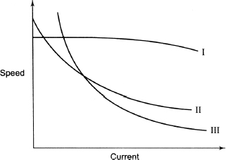
14. It is desired to have a reverse DC motor which is possible if
| (a) the field coil is split | (b) supply to the motor is reversed by a switch |
| (c) polarity of supply is changed by a relay | (d) all of the above |
15. Match the following
| (a) DC series motor | (1) Factory shafting, machine tools |
| (b) DC shunt motor | (2) Electric traction, cranes, lift |
| (c) DC compound motor | (3) Conveyers, punch processes |
16. Speed of a DC shunt motor is proportional to
(a) ![]() (b)Ia (c)Ia2 (d) none of these
(b)Ia (c)Ia2 (d) none of these
17. Back emf of a DC shunt motor depends on
| (a) number of armature conductors | (b) field flux |
| (c) armature speed (N) | (d) none of these |
18. The armature of a DC motor is laminated
| (a) to reduce hysteresis loss | (b) to reduce eddy current loss |
| (c) to reduce copper loss | (d) none of these |
19. Maximum mechanical power is developed when back emf equals to
| (a) half of the applied voltage | (b) the applied voltage |
| (c) double of the applied voltage | (d) one-third of the applied voltage |
20. A DC series motor should not be started
| (a) at full-load | (b) at no-load |
| (c) with normal load |
21. The torque speed characteristic of a DC series motor is
| (a) rectangular hyperbola | (b) parabola |
| (c) linearly rising | (d) linearly declining |
22. When an electric train moves down a hill, the DC motor behaves as a
| (a) DC shunt generator | (b) DC series generator |
| (c) DC shunt motor | (d) none of these |
23. Find the motor which is used for rolling mills:
| (a) DC shunt mot | (b) DC series motor |
| (c) DC differentially compound motor | (d) DC cumulatively compound motor |
24. The main drawback of field control method of speed control is
- (a) its low frequency
- (b) that commutation becomes unsatisfactory
- (c) that only speed above normal can be achieved
- (d) all of these
25. Stalling current is the maximum value of
| (a) load current for which speed is zero | (b) load current for which speed is maximum |
| (c) field current for which speed is maximum | (d) field current for which speed is zero |
26. If the field winding of a DC shunt motor is opened, the speed of the motor will be
| (a) increased to an unstable value | (b) reduced |
| (c) reversed | (d) zero |
27. If the load of a DC shunt motor is increased, its speed will
| (a) increase proportionately | (b) decrease slightly |
| (c) increase slightly | (d) remain constant |
28. The developed torque of a DC shunt motor is proportional to
(a) ![]() (b)
(b)![]() (c)
(c) ![]() (d)
(d)![]()
29. The developed torque of a DC series motor is proportional to
(a)![]() (b)
(b)![]() (c)
(c)![]() (d)
(d)![]()
30. Compound motors are used when
- (a) load increases with increase in speed
- (b) load is alternating sinusoidally
- (c) there are large load variations and load equalization is done by flywheel
- (d) all of the above
31. In Swinburn’s method of testing, the DC machine is run as
| (a) motor at no-load | (b) motor with break load applied at rated load |
| (c) generator connected to rated load | (d) all of the above |
32. In Hopkinson’s method of testing DC machines, the power is used to supply the losses in
| (a) generator only | (b) motor only |
| (c) motor at rated load only | (d) both (a) and (b) |
33. Ward-Leonard method of speed control
- (a) has low efficiency at light loads
- (b) has high maintenance and initial costs
- (c) can provide speeds below and above normal in both directions
- (d) minimum three machines are used
- (e) is a voltage control method
- (f) all of the above
34. A 200 V DC shunt motor develops a torque of 54 N-m at an armature current of 10 A. The torqueproduced, when the armature current is 20 A, is
(a) 54 N-m (b) 81 N-m (c) 108 N-m (d) none of these
35. A shunt motor works on AC mains
(a) unsatisfactorily (b) satisfactorily (c) not at all (d) none of the above
36. A DC shunt motor is operating at no-load. If the armature is shunted by a resistance, its speed will
(a) increase (b) decrease (c) remain the same (d) be unpredictable
37. A DC shunt motor drives a load at rated speed and supply voltage. If both the load and voltage are halved, the speed will be
| (a) almost double | (b) almost half |
| (c) the rated speed | (d) slightly less than the rated speed |
38. A DC shunt motor does not operate on AC due to
| (a) low resistance of armature circuit | (b) high resistance of field circuit |
| (c) high inductance of field circuit | (d) reversal of polarity |
39. The function of brush and commutation in a DC motor is
- (a) to convert DC into AC
- (b) to produce unidirectional torque
- (c) to produce unidirectional current in the armature
- (d) to reduce demagnetizing effect of armature reaction
40. The field windings of a DC compound motor are connected in short-shunt configuration. If the series and shunt field windings are interchanged and the motor is connected to a rated voltage, then
| (a) series winding gets overloaded | (b) shunt winding gets overloaded |
| (c) neither of the windings gets overloaded | (d) both windings get overloaded |
Answers