
4 DC Generators
Direct current (DC) generators are machines that convert mechanical energy to electrical energy. This conversion of energy is based on the principle of the production of dynamically induced electromotive force (emf). In a DC generator the field is on the stator, whereas the armature is on the rotor. The field coil is excited by a DC supply. The rotor is rotated with the help of a prime mover, thereby cutting the flux produced by the field coils. The armature cuts the rotor flux and an alternating emf is induced in it, which is converted into a unidirectional emf with the help of the commutator. The basics of DC machines have been introduced in Chapter 3. This chapter introduces other aspects of the DC generators.
4.1 TYPES OF DC MACHINES
The classification of the DC machines based on the field configuration is as follows:
(i) Homopolar machines.
(ii) Heteropolar machines.
Homopolar machines: These types of machines are used where low voltage and high currents are required. Faraday’s disc dynamo is an example of this type of machine.
Heteropolar machines: The DC machines that are commonly used fall under this category.
4.2 DC GENERATOR
The classification of the DC generators, depending upon their field excitation, is as follows:
- Separately excited generator: In this type of generator, the field coils are energized from an independent external source, as shown in Figure 4.1(a).
- Self-excited generator: In this type of generator, the field coils are energized by the current produced by the generator itself. These types of generators are classified into the following three categories, depending upon their field connections:
- Shunt-wound generator: The field winding is connected in parallel to the armature. So, the full terminal voltage of the generator is applied across the field winding, as shown in Figure 4.1(b). The resistance of the field coil is very high.
- Series-wound generator: The field winding is connected in series with the armature. Since the field carries the full-load current, it consists of relatively few turns of thick wires, as shown in Figure 4.1(c). The resistance of the field coil is very low.
- Compound-wound generator: This type of generator is actually a combination of a few series-wound and a few shunt-wound generators. It can be either long shunt, as shown in Figure 4.1(d) or short shunt, as shown in Figure 4.1(e). If the series field aids the shunt field, the generator is said to be cumulatively compounded. If the series field opposes the shunt field, the generator is said to be differentially compounded.
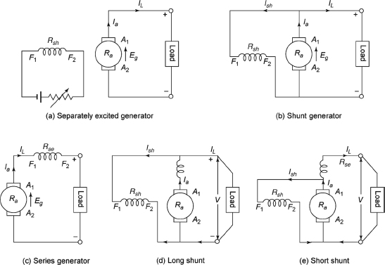
Figure 4.1 Classification of DC Generators
4.3 BRUSH DROP
The brush at first collects current from the commutator. Therefore, a contact drop occurs across the brush. For the metal graphite brushes, this drop is 0.5 V and for the carbon brushes it is 2.0 V
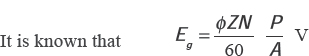
4.4 EMF EQUATION
| Let, | Vt be the terminal voltage, |
| Ia be the armature current, | |
| Ra be the armature resistance, | |
| Eg be the generated voltage in armature and | |
| IL be the load current. |
4.4.1 Shunt Generator
Let Rsh be the resistance of the field coil and Ish be the field current. The following equations are valid:
![]()
![]()
where Vbrush is the total voltage drop across the brush.
4.4.2 Series Generator
Let Rse be the series field resistance and I be the field current. The following expressions are valid:
![]()
![]()
4.4.3 Long-shunt Compound Generator
The shunt field winding is connected across the series combination of the armature and series field winding.
![]()
![]()
where Ise and Ish are the currents through the series and shunt field windings.
The voltage across the shunt field winding is Vt. The shunt field current (Ish) is expressed by
![]()
where Rsh is the resistance of shunt field winding.
The voltage equation becomes
![]()
where Rse is the resistance of series field winding.
4.4.4 Short-shunt Compound Generator
The shunt field winding is connected across the armature only.
![]()
![]()
![]()
The drop across the shunt field winding is the drop across the armature only and not the total Vt. Therefore, the drop across the shunt field winding is Eg -Ia Ra.
![]()
The voltage equation is expressed by
![]()
![]()
Equation (4.13) in terms of IL becomes
![]()
![]()
Substituting Eg - IaRa in Equation (4.12), we have
![]()
From the emf equation, we can conclude that Eg is always greater than Vt. The expression for Eg is derived in Section 4.5.
4.5 DERIVATION FOR Eg
Eg depends on the following factors:
(i) The magnetic flux Φ (Wb).
(ii) The speed of the machine (rps or rpm).
(iii) A constant that depends on the construction of the machine.
The emf (Eg) in a conductor of active length l moving at a velocity u in a magnetic field having flux density B is given by the following equation:
![]()
| Let, | Φ be the flux/pole (Wb), |
| P be the number of generator poles, | |
| Z be the total number of armature conductors, | |
| A be the number of parallel paths and | |
| N be the speed of armature in rpm. |
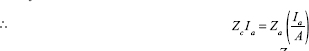
The number of conductors in series =Z/A. The emf generated is expressed by the following equation:
![]()
where B is the magnetic flux density, l is the length of the conductor and u is the velocity. The flux density can be expressed as
![]()
![]()
where r is the radius of the armature
![]()
Using Equations (4.20) and (4.21), Equation (4.19) can be expressed as
![]()
![]()
For lap winding, A = P and for wave winding, A = 2.
Example 4.1 A four-pole generator, having wave-wound armature winding has 55 slots, each slot containing 19 conductors. What will be the voltage generated in the machine when driven at 1,500 rpm assuming that the flux per pole is 3.0 mWb?
Solution
Here, Φ = 3 × 10³ Wb, Z = 55 × 19 = 1,045, A = 4, P = 2, N = 1,500rpm
![]()
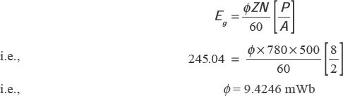
Example 4.2 The terminal voltage of an eight-pole DC shunt generator with 780 wave-connected armature conductors and running at 500 rpm at terminal voltage is 240 V. The armature resistance is 0.24Ω and the field resistance is 240Ω. Find the armature current, the induced emf and the flux per pole if the load resistance is 12Ω .
Solution
| Here, | Z = 780 |
| Number of parallel paths (A) = 2 (due to wave winding) | |
| Load current = V/R = 240/12 = 20 A | |
| Shunt current = 240/240 = 1 A | |
| Armature current = 20 + 1 = 21 A | |
| Induced emf = 240 + (21 x 0.24) = 245.04 V |
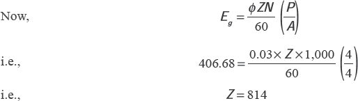
Example 4.3 A four-pole, long-shunt lap-wound DC generator supplies 20 kW at a terminal voltage of 400 V The armature resistance is 0.04Ω, series field resistance is 0.05Ω and shunt field resistance is 200Ω. The voltage drop per brush may be taken as 1.0 V. Determine the emf generated.
Also, calculate the number of conductors if the speed is 1,000 rpm and flux per pole is 0.03 Wb. Neglect the armature reaction.
Solution
I = 20,000/400 = 50 A
Ish = 400/200 = 2
Ia = I + Ish = 50 + 2 = 52 A
Series field drop = 52 × 0.05 = 2.6 V
Armature drop = 52 × 0.04 = 2.08 V
Brush drop = 2 × 1 = 2 V
General emf Eg = 400 + 2.6 + 2.08 + 2 = 406.68 V
4.6 LOSSES IN DC GENERATOR
The following losses occur in a DC generator:
- Copper loss:
- Armature Cu-loss = I2a Ra, where Ra is the resistance of the armature and Ia is the armature current.
- For the shunt generators the field Cu-loss is equal to I2sh Rsh, where Rsh is the resistance of the shunt field winding and Ish is the current through it. This loss for shunt generator is practically constant. For the series generator it is equal to I 2se Rse, where Rse is the resistance of the series field winding and Ise is the current through it. Field Cu-loss is also constant for the compound generators. This loss is about 20-30 per cent of full-load losses.
- The loss due to brush contact is generally included in armature Cu-loss.
- Magnetic loss or iron loss or core loss:
- Hysteresis loss: This loss occurs due to reversal of the armature core. Each portion of the rotating core passes under the north (N) and south (S) pole alternately and attains S and N polarity, respectively. When the core passes under one pair of poles, the core is said to complete one cycle of frequency reversal. Hysteresis loss ∝ Bnmaxf (n is generally 1.6). The frequency of magnetic reversal
 Hz, where P is the number of poles and N is the speed of the armature in rpm. To reduce this loss, material having small hysteresis loop should be used.
 - Eddy current loss: The armature core cuts the magnetic flux during its rotation and emf is induced in the body of the core according to the laws of electromagnetic induction. This emf is very small, but it sets up a large current in the body of the core. This current is called the eddy current and the loss is known as the eddy current loss. Eddy current loss ∝B2maxf2. These losses are reduced by using laminated core.
Iron losses are constant for shunt and compound generators, as their field currents are approximately constant. This loss is about 20–30 per cent of full-load loss.
- Mechanical losses
- Air friction or windage loss of rotating armature.
- Friction loss at bearings and commutator, which are about 10–20 per cent of full-load losses. Mechanical losses together are known as stray losses.
4.7 STRAY LOSSES
The magnetic and mechanical losses are collectively known as stray losses, which are also known as rotational losses.
4.8 CONSTANT OR STANDING LOSSES
The shunt and compound generators have constant field Cu-loss. Therefore, stray losses and shunt Cu-losses are constant in these types of generators. The sum of these two losses is known as standing or constant losses denoted by Wc.
4.9 POWER STAGES
Figure 4.2 shows the various power stages of the DC generators.
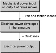
Figure 4.2 Various Power Stages of DC Generators
4.10 EFFICIENCY
DC generators have the following efficiencies due to the different power stages:
- Mechanical efficiency:
![]()
- Electrical efficiency:
![]()
- Commercial or overall efficiency:
![]()
∴ ηc = ηm × ηn.
Commercial efficiency is always to be taken if it is not specified. Since the commercial efficiency is the product of the mechanical and electrical efficiencies, ηc is always less than ηe and ηm.
Example 4.4 A DC shunt generator delivers 195 A at terminal voltage of 200 V. The armature resistance and the shunt field resistance are 0.03Ω and 40Ω, respectively. The iron and friction losses are equal to 900 W. Find the following: (i) emf generated, (ii) Cu-losses, (iii) output of the prime mover and (iv) commercial, mechanical and electrical efficiencies.
Solution
(i) Ish = 200/40 = 5 A; Ia = 195 + 5 = 200 A
Armature voltage drop = IaRa = 200 x 0.03 = 6 V
∴ Generated emf(Eg) = 200 + 6 = 206 V
(ii) Armature Cu-loss = I2Ra = 2002 x 0.03 = 1,200 W
Shunt Cu-loss = VIsh = 200 x 5 = 1,000 W
∴ Total Cu-loss = 1,200 + 1,000 = 2,200 W
(iii) Stray losses = 900 W
Total losses = 2,200 + 900 = 3,100 W
Electrical power output = 200 x 195 = 39,000 W
Output of prime mover = 39,000 + 3,100 = 42,100 W = 42.1 kW
(iv) Generator input = 42,100 W
Here, stray losses = 900 W
Electrical power produced in armature = 42,100 – 900 = 41,200 W
![]()
Total Cu–losses = 2,200 W

Also, ηC = ηm ηe 0.92636 p.u. = 92.636%.
4.11 CONDITION FOR MAXIMUM EFFICIENCY
Figure 4.3 shows the variation of efficiency (η) of a DC generator with the load current. The value of η increases with an increase in the load current (I). For a particular value of I, η is maximum. With further increase of I, η decreases. Therefore, η is a function of I. Let us find the condition of maximum efficiency.
Since I sh is negligible order compared to I L, IL = I a = I (say)
Generator output = Vt I
Generator input = Output + Losses
= Vt I + I 2 Ra+ Wc

Figure 4.3 Efficiency Versus Current
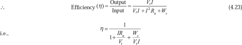
Now, η will be maximum when denominator of Equation (4.23) becomes minimum.
Hence, generator efficiency is maximum when
Constant loss = Cu-loss or variable loss
The load current at which maximum frequency occurs is given by
![]()
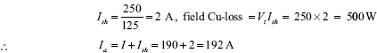
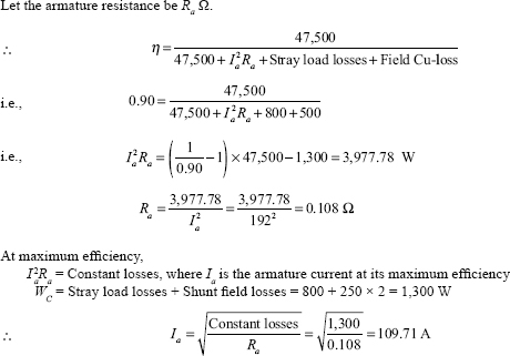
Example 4.5 The terminal voltage and the load current of a DC shunt generator are 250 V and 190 A. The field coil resistance and the stray load losses are 125Ω and 800 W. Find the armature resistance if it has a full-load efficiency of 90 per cent. Calculate the load current at maximum efficiency.
Solution
Here, I = 190 A, Vt = 250 V, stray load losses = 800 W, nfl = 90%
Output power = 190 × 250 = 47,500 W
4.12 ARMATURE REACTION IN DC MACHINES
The armature magnetomotive force (mmf) has an effect on the magnitude and distribution of the field in the air gap and also in the armature core. This effect is known as the armature reaction. The following are the effects of armature magnetomotive force on the main field flux:
- It partly weakens or demagnetizes the main field flux.
- It cross magnetizes or distorts the main field flux.
Figure 4.4(a) shows a two-pole machine having six slots and two conductors per slot. Figure 4.4(b) shows the distribution of the main field flux when the armature conductor carries no current, and at this stage the position of brushes is at the geometrical neutral axis (GNA), which coincides with the magnetic neutral axis (MNA). The bottom conductors have not been shown for simplicity. The developed armature along with the main field flux is shown in Figure 4.4(b), where the waveform of flux is plotted with an assumption that the flux entering the armature through the air gap of the field system is taken as positive, and hence the waveform under the north pole is taken as positive, whereas the one under the south pole is taken as negative.
Figure 4.5(a) shows an armature with two slots and one conductor per slot. The distribution of flux is from F to E for the given distribution of armature currents. The armature becomes an electromagnet, and its poles have been indicated. The flux due to the armature coils (a,b) that enters the air gap field is taken as positive. Figure 4.5(b) shows the waveform of the mmf of the coil shown in Figure 4.5(a).
Figure 4.6 shows the distribution of the armature mmf when armature carries current as a generator and it rotates in the anticlockwise direction.
Figure 4.7(a) shows the developed view of the armature of Figure 4.6 to obtain the mmf waveform of armature currents. Any two conductors forming one turn are situated a pole pitch apart. The end connectors are shown by dotted lines in Figure 4.7(a). Each coil, in the allotted time, develops mmf, which is represented by small rectangular steps spreading across the breadth of the coil, as shown in Figure 4.7(b). The conductors lying in between the vertical axes C1C2 and D1D2 act as if they form the concentric coils producing a stepped mmf waveform and its maximum value along the geometric neutral axis A2A1. The stepped mmf waveform is taken as negative because the mmf is directed from the armature core to the field system. The mmf due to the conductors situated in the left of the axis C1C2 and in the right of the axis D1D2 forms a stepped wave directed along B2B1. The stepped mmf waveform transforms into a triangular waveform, as shown in Figure 4.7(c), when the armature conductors are distributed uniformly around the periphery of the armature. The peak value is calculated below.
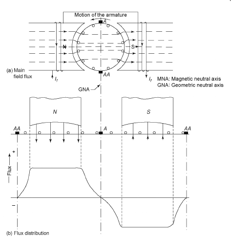
Figure 4.4 Main Field Flux and Flux Distribution when the Armature Is on No Load
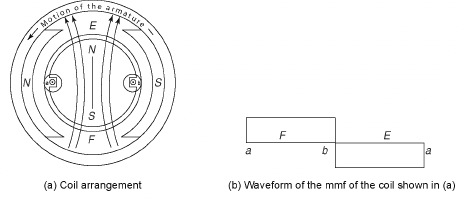
Figure 4.5 Coil Arrangement and Waveform of mmf

Figure 4.6 Flux Distribution Due to the Armature Current
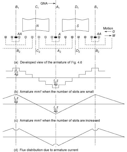
Figure 4.7 Distribution of the Armature mmf
Let Ia be the total current in the armature and 2a be the number of parallel paths.
The current per conductor (Ic) = ![]() . The number of ampere conductors on the armature = Ic Z and the number of ampere conductors per pole =
. The number of ampere conductors on the armature = Ic Z and the number of ampere conductors per pole = ![]() , where p is the number of pair of poles.
, where p is the number of pair of poles.
The number of ampere turns per pole ![]()
![]()
The mmf represented by Equation (4.26) acts along the brush axis. At the positions of the uniform reluctance of the air gap, the waveforms of mmf and the flux distribution due to armature are identical. Since the reluctance of the air gap at the interpolar gap between the poles is more as compared to the value under the poles, a kink is introduced in the flux waveform along with the GNA and symmetrical with respect to it, as shown in Figure 4.7(d). The zeros of the main field flux pass through the GNA shown in Figure 4.5(b) when the armature carries no current, which means that the MNA coincides with the GNA.
Figure 4.8(a) shows the developed view of the armature, and Figure 4.8(b) shows the distribution of the field and the armature fluxes for the motion of the armature from right to left when acting as a generator. The resultant flux due to the main field flux and the armature flux is shown in Figure 4.8(c) in which distortion of the main field flux has been clearly depicted. From Figure 4.8(c), it is obvious that the total flux decreases at the leading pole tip, whereas it increases at the trailing pole tip. The axis CD is the MNA that is normal to the resultant flux in the core, which is shifted from the axis A-AA by an angle θ in the direction of rotation of the machine when it acts as a generator and in the opposite direction when it acts as a motor. The resultant waveform, shown in Figure 4.8(c), is obtained by the superposition of the two flux waveforms. The peak value RS of the resultant flux at the trailing pole tip is obtained by adding fluxes LM and L´K of the main field flux and the armature flux at the trailing pole tip, respectively. The armature flux and the main field flux reinforce each other at the trailing pole tip, whereas they oppose each other at the leading pole tip. The zero of the resultant waveform is shifted by an angle θ in the direction of rotation for the case of generator and in the opposite direction for the case of motor. This means that the MNA shifts in the forward direction for the generator and in the backward direction for the motor. If the direction of rotation of the machine for motoring mode is assumed from left to right, the waveform remains unaltered. For good commutation, the brush axis must coincide with the MNA. Hence, the brush axis must be placed along CD when the armature is under load instead of placing it along the GNA during load. Therefore, the effect of armature flux not only distorts the main field flux waveform but also partly weakens the main field flux at the leading pole tip, which is called the armature reaction. If the saturation is present in the teeth of the armature, the peak of the resultant waveform will be rounded off. If the working flux density is high, the effect of the armature reaction can be minimized.
The iron losses in the teeth and the pole shoes of the armature depend on the maximum value of the working flux density in the regions. Due to the armature reaction, the maximum flux density increases under the trailing pole tip, whereas it decreases at the leading pole tip. Hence, the iron loss on the teeth is greater on load than on no load. Due to very high degree of magnetic saturation in the teeth, some of the flux gets its way into the core end plates that are fairly massive and induces eddy current, which gives rise to appreciable losses. During load, the extra iron loss of about 50 per cent of the no-load iron losses occur in the machine.
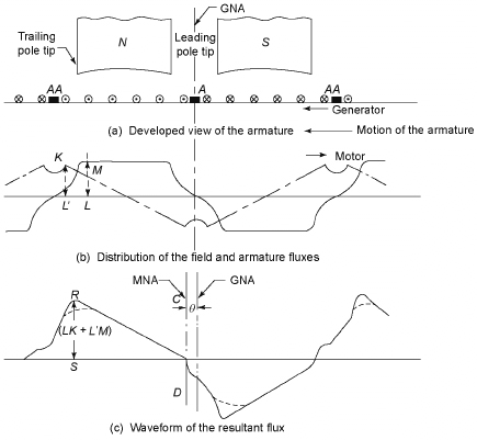
Figure 4.8 Resultant Flux of Loaded and Unsaturated DC Machines
4.13 DEMAGNETIZING AND CROSS-MAGNETIZING CONDUCTORS
Figures 4.9(a) and 4.9(b) show the armature conductors that produce the demagnetizing and cross-magnetizing effects when brush axis lies in the new position of the MNA, having a forward lead of θ The direction of the currents through the conductors lying within angles AOC and BOD, shown in Figure 4.9, is such that the flux through the armature is from left to right, and hence produces demagnetizing effects, whereas the direction of the currents through the conductors lying within the angles AOD and COB is such that the combined flux is at right angles to the main flux, and hence causes cross-magnetizing effects, as shown in Figure 4.9 (b).
4.14 DEMAGNETIZING AMPERE-TURNS PER POLE
To neutralize the demagnetizing effects, extra ampere-turns (AT) are added to the main field winding and calculation of the extra AT is required.
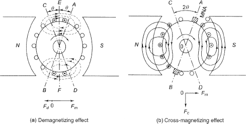
Figure 4.9 Demagnetizing and Cross-magnetizing Effects
Let Z= number of armature conductors,
θm = forward lead to mechanical or geometrical or angular degrees,
I = current in each armature conductor,
= Ia/2 for simplex wave winding,
= Ia/P for simplex lap winding.
The total number of armature conductors within the angles AOC and BOD = ![]()
Therefore, the total number of turns in angles AOC and BOD = ![]()
The total number of AT in angles AOC and BOD = ![]()
Therefore, the demagnetizing AT per pair of poles = ![]()
![]()
4.15 CROSS-MAGNETIZING AMPERE-TURNS PER POLE
The cross-magnetizing conductors lie within the angles AOD and BOC, as shown in Figure 4.7(b).
The total number of conductors including cross-magnetizing and demagnetizing is given by![]()
As derived earlier, demagnetizing conductors per pole = ![]()
Therefore, cross-magnetizing conductors per pole 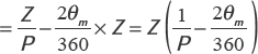
The cross-magnetizing ampere-conductors per pole 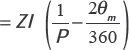
H ence, the cross-magnetizing AT per pole 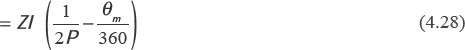
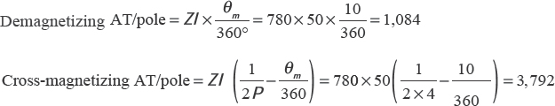
Example 4.6 A wave-wound four-pole DC generator with 780 armature conductors supplies 100 A. The brushes are given an actual lead of 10° (mechanical). Calculate the armature demagnetizing and cross-magnetizing AT per pole.
Solution
P = 4, parallel path (A) = 2, Z=780, armature current (Ia) = 100 A (assuming armature current=load current).
Therefore, current per parallel path ![]()
Brush shift (θm ) = 10° (mechanical)
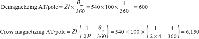
Example 4.7 A wave-connected, eight-pole, 60 kW, 300 V DC generator has 540 conductors and delivers full-load current. If the brush shift is 4° (mechanical), calculate demagnetizing and cross-magnetizing AT/pole.
Solution
![]()
Armature current (Ia) = 200 A (assuming armature current = load current)
Therefore, current per parallel path ![]()
Angle shift (θm) = 4° (mechanical)
4.16 COMPENSATING WINDINGS
Compensating windings are used for large DC machines to neutralize the cross-magnetizing effect of armature reaction. Large DC machines are subjected to major fluctuation of loads. In the absence of compensating windings the flux shifts backwards and forwards due to change of load, which induces statically induced emf in armature conductors. The change of load determines the magnitude of this induced emf. The magnitude of this induced emf may be very high, resulting in a flash-over around the whole commutator circuit. Therefore, the whole armature circuit gets short circuited. These windings that are embedded in the pole shoes and connected in series with the armature are shown in Figure 4.10. Connections are made in such a way that the direction of the current in these conductors is opposite to the direction of the current in the armature conductors. The mmfs of the compensating windings should be sufficient to counterbalance the armature mmfs.
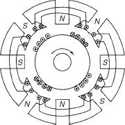
Figure 4.10 Compensating Windings
Let Za be the number of active armature conductors/pole,
Ia be the current/armature conductors,
A be the number of parallel paths and
Zc be the number of compensating conductors/pole face.
![]()
Compensating windings are generally used in large DC machines.
4.17 NUMBER OF COMPENSATING WINDINGS
The number of armature conductors/pole ![]()
Therefore, the numbers of armature turns per pole ![]()
The number of armature-turns immediately under one pole ![]()
Approximately, the number of armature-turns immediately under one pole 
Therefore, the number of AT/pole for compensating windings ![]() 0.7 × armature amp-turns/pole
0.7 × armature amp-turns/pole
4.18 COMMUTATION
In DC generators, the brush width is greater than the width of a commutator segment and the mica insulation. The armature coils connected to the commutator segments become short circuited during the spanning of the brush. Commutation is the process of collection of current by the brush or the changes that takes place in a coil during the period of short circuit by a brush. The induced current in the armature conductors of the DC generators is alternating in nature. Commutator are used to make their flow unidirectional. The armature conductors that are under the infl uence of the north poles carry current in one direction and that are under south poles carry current in the opposite direction. Therefore, if the conductors under the infl uence of the north pole come under the infl uence of the south pole, the direction of current through the conductors changes. Current in theses conductors changes from + I to 0 and then from 0 to - I. Similar change occurs when conductors under the infl uence of the south pole come under the infl uence of the north pole. Current in these conductors changes from - I to 0 and then from 0 to + I. The direction of current through the armature conductors also changes. This reversal of current occurs along the MNA. If this changing of current from positive to zero and then from zero to positive is completed by the end of the short circuit or the commutation period, the commutation is said to be ideal. There will be sparking at the brush and commutator segments. Otherwise, this sp rking will damage both.
To discuss the process of commutation, let us consider Figure 4.11. Figure 4.11(a) shows that the brush is about to touch the commutator segment a, and hence coil B is about to be short circuited. If all the coils carry currents of 40 A, the current in the brush at this stage is 80 A because every coil supplies 40 A to the brush. Figure 4.11(b) shows that coil B has entered its short circuit, which is one-third of its period. The current through coil B is 20 A, as shown by the arrow. Figure 4.11(c) shows that the coil is in the middle of its short circuit period; therefore, the current through it is zero. Figure 4.11(d) shows that the brush contact area with commutator b has decreased rapidly, whereas its contact area with the commutator a has increased. Now, the coil B carries a current of 20 A in the direction opposite to that in Figure 4.11(b). Figure 4.11(e) shows almost the end of the commutation period. In this case, the current through coil B is 30 A instead of 40 A. The 10A current flows from the commutator segment b to the brush via air, which results in sparking. Since the coils are embedded in the armature, armature is made up of materials of high permeability. Therefore, the coils posses appreciable amount of self-inductance. Hence, it is very difficult to get ideal commutation. Figure 4.12 shows the changes of the current through coil B.
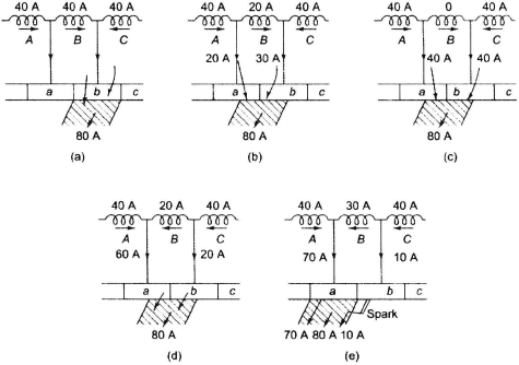
Figure 4.11 Process of Commutation
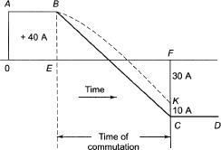
Figure 4.12 Changes of Current Through Coil B
4.18.1 Linear Commutation
4.13(a) shows the position of the brush on the commutator having length, width and thickness of l, b and d, respectively. The thickness of the brush is assumed to be equal to the width of each commutator segment, neglecting the thickness of the mica separation between the segment to simplify the analysis. The current in the coil undergoing commutation is not zero due to the use of short-pitched coils and also due to self-inductance of the coil. Figure 4.13(b) shows the coil undergoing commutation.
Let i be the current in coil 1 that is undergoing commutation, x be the breadth of the contact between segment 2 and the entering edge of the brush, I1 be the current delivered to the brush by segment 1, I2 be the current delivered to the brush by segment 2, ![]() be the current per circuit in the armature.
be the current per circuit in the armature.
The total current at the brush = I1 + I2 = Ia. The current density under the brush is assumed to be uniform. We have
![]()
![]()
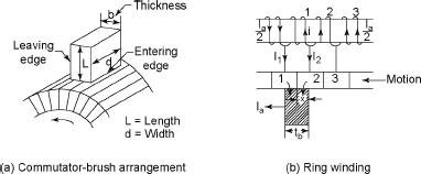
Figure 4.13 Coil Undergoing Commutation
The commutation in coil 2 starts when x = 0 and ends when x = b. The time is measured from the instant of commencement of commutation. Let Vc be the linear velocity of the commutator in m/s and t be the time taken to cover the distance x, then
![]()
and time of commutation
![]()
Let the current in the coil undergoing commutation at any instant t be i and direction of the current in the coil before commutation be positive. We have
![]()
![]()
![]()
![]()
From Equations (4.34) and (4.35), we have
![]()
![]()
Substituting I2, using Equation (4.31) in Equation (4.35), we have
![]()
From Equations (4.32) and (4.33), we have
![]()
Substituting ![]() , using Equation (4.39) in Equation (4.38), we have
, using Equation (4.39) in Equation (4.38), we have
![]()
Equation (4.40) shows the variation of the current with time, and this plot has been shown in Figure 4.14, where i varies linearly from ![]() in time Tc. The current density under the brush remains constant, which is denoted by Jm during the period of commutation.
in time Tc. The current density under the brush remains constant, which is denoted by Jm during the period of commutation.
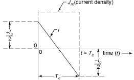
Figure 4.14 Linear Commutation
4.18.2 Retarded Commutation
The variation of the current in the coil undergoing commutation is not linear in practice. Due to the presence of self-inductance, the commutation is delayed. Therefore, the current density at the leaving edge of the brush will be greater and that at the entering edge will be less than the value with straight-line commutation.
Figure 4.15 shows the graph of the short-circuited current as a function of time, where i represents the current in the short-circuited coil. The current entering at the leaving edge of the brush is expressed by ![]() , which is also shown in Figure 4.15, adding
, which is also shown in Figure 4.15, adding ![]() to i. The contact area of the brush on the segment at the leaving edge varies linearly from b x d at t = 0 to zero at the end of commutation. The variation of the contact area with respect to the time is represented by a straight line. At any instant t, the current carried by the segment at the leaving edge = PN, having the contact area QN. The current density at the segment=
to i. The contact area of the brush on the segment at the leaving edge varies linearly from b x d at t = 0 to zero at the end of commutation. The variation of the contact area with respect to the time is represented by a straight line. At any instant t, the current carried by the segment at the leaving edge = PN, having the contact area QN. The current density at the segment=![]()
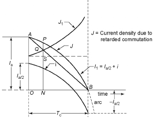
Figure 4.15 Variation of Current Density at the Leaving Edge of the Brush
The current density J1 at the leaving edge increases with time because the contact area at the segment decreases more rapidly than the current. The current density may reach the value 2.5 times its initial value at the end of breaking of contact with the brush at time t = Tc. Figure 4.16 shows the plot of current density with time at the entering edge of the brush. The current through the segment at the entering edge of the brush is expressed by ![]() , which is shown in Figure 4.16, adding
, which is shown in Figure 4.16, adding ![]() to -i. I2 varies from zero at t = 0 at Ia to t = Tc, which means that the current density attains its normal value at the end of commutation. It is less than the normal value Jm for the major part of the commutation period.
to -i. I2 varies from zero at t = 0 at Ia to t = Tc, which means that the current density attains its normal value at the end of commutation. It is less than the normal value Jm for the major part of the commutation period.
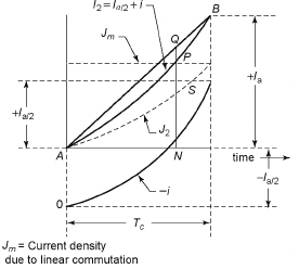
Figure 4.16 Variation of the Current Density at the Entering Edge of the Brush
For retarded commutation, the current at the segment at the leaving edge attains zero instead of ![]() at the end of commutation, as shown in Figure 4.15, and the arcing results at the end as the current 2I suddenly changes from 0 to
at the end of commutation, as shown in Figure 4.15, and the arcing results at the end as the current 2I suddenly changes from 0 to ![]() .
.
4.18.3 Accelerated Commutation
Figure 4.17 shows that the brush axis is in forward undergoing commutation can be aided. Coil 1 will immediately in the front of the coil if the brush axis is shifted by a small angle θ from the axis A-AA in the direction of the motion. At this time, the emf generated in coil 1 will assist in forcing the reversal of current in the coil.
Figure 4.18 shows the current i in coil 1 with accelerated commutation. In each armature path, the current becomes ![]() , and the total current collected by the brush becomes Ia = AC. Figure 4.18 shows the variation of the current density at the leaving and entering edges with accelerated commutation. At any time t, the current in the segment leaving the brush becomes
, and the total current collected by the brush becomes Ia = AC. Figure 4.18 shows the variation of the current density at the leaving and entering edges with accelerated commutation. At any time t, the current in the segment leaving the brush becomes ![]() , and the current in the segment entering the brush
, and the current in the segment entering the brush ![]()
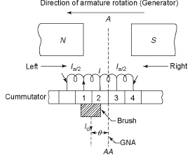
Figure 4.17 Accelerated Commutation with the Forward Shift in the Position of Brush Axis
The following are the corresponding values of the current for linear commutation.

The ratio of the currents at the entering edge with accelerated commutation to that with linear commutation ![]() . The current density at the leading edge is
. The current density at the leading edge is
![]()
The ratio of the currents at the entering edge with accelerated commutation to that with linear communication ![]() . The current density at the entering edge
. The current density at the entering edge
![]()
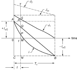
Figure 4.18 Variation of the Current Density at the Leaving and Entering Edges
The current density at the leaving edge of the brush at the end of commutation is
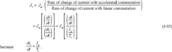
If ![]() at T = Tc, then J1 = 0. This causes breaking of sparing at the contact of the segment with the brush at the leaving edge. Similarly, the current density at the segment entering the brush will be
at T = Tc, then J1 = 0. This causes breaking of sparing at the contact of the segment with the brush at the leaving edge. Similarly, the current density at the segment entering the brush will be
From Figure 4.18, ![]() at t=0 and the current density is more than Jm. This causes sparking at the entering edge of the brush. The current density in the segment must be zero at the time of entering of the brush as well as at the time of leaving of the brush to ensure commutation without sparks.
at t=0 and the current density is more than Jm. This causes sparking at the entering edge of the brush. The current density in the segment must be zero at the time of entering of the brush as well as at the time of leaving of the brush to ensure commutation without sparks.
4.18.4 Sinusoidal Commutation
For retarded commutation, J2 = 0 at t = 0 and J1 ≥ Jm at t = Tc, and sparking occurs at the leaving edge of the brush because J1 ≠ 0 at the time of breaking of the contact of the segment with the brush.
For retarded commutation, J2 ≠ 0 at t = 0 and J1 = 0 at t = Tc and sparking occurs at the time of contact segment approaching the brush, since J2 ≠ 0 at the time when the segment is about to make contact with the brush.
Therefore, to obtain sparkless commutation, the variation of the current in the coil undergoing commutation must be retarded in the first half of the commutation and must be accelerated in the next half of the commutation, as shown in Figure 4.19.
Figure 4.19 shows the current densities J1 and J2. At t ≠ 0, J2 = 0 at the entering segment and J1 = 0 at t = Tc at the leaving segment. This results in sparkles commutation at the making and breaking contacts of the segment.
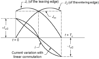
Figure 4.19 Sinusoidal Commutation
4.19 VALUE OF REACTANCE VOLTAGE
The self-induced emf is generated in the coils that makes the proper current reversal of the conductors impossible at the time of commutation. This self-induced emf is called reactance voltage.
Therefore, reactance voltage = co-efficient of self-inductance x rate of change of current.
The time of short circuit or commutation is the time required by the commutator to move a distance equal to the circumferential thickness of the brush minus the thickness of one insulating plate or strip of mica.
Let Wb be the width of brush in cm,
Wm be the width of mica insulation in cm and
vc be the peripheral velocity of the commutator segments in cm/sec.
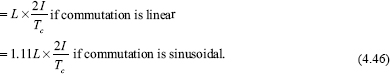
![]()
If I is the current through the conductor, the total change of current during commutation
= I–(−1)=2I
Reactance voltage or self-induced voltage
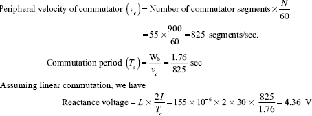
Example 4.8 Calculate the reactance voltage for a machine having the following parameters: Number of commutator segments = 55, revolutions per minute = 900, brush width in commutator segments = 1.76, co-efficient of self-induction = 155 x 10-3 H and current per coil = 30 A.
Solution
Current per coil (I ) = 30 A.
Self-inductance of coil (L ) = 155 × 10-3 H
4.20 METHODS OF IMPROVING COMMUTATION
There are two methods available for improving commutation:
- Resistance commutation.
- emf commutation.
4.20.1 Resistance Commutation
In this method, low-resistance copper brushes are replaced by comparatively high-resistance carbon brushes.
Figure 4.20 shows the current I from C reaching commutator segment b. There are two paths for the current to reach the commutator segments. The first path is through bar b to the brush and the other is via the short-circuited coil B to bar a and then to the brush. If copper brushes are used, current will not follow the second path. If carbon brushes are used, current will follow the second path instead of the first path for the following reasons:
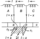
Figure 4.20 Resistance Commutation
- The resistance of the first path increases because the area of contact of bar b diminishes.
- The resistance of the second path decreases because the area of contact of bar a increases.
Carbon brushes have the following advantages:
- Their high contact resistance is useful for good commutation.
- They lubricate and polish the commutator during rotation.
- In spite of sparking, carbon brushes cause less damage to the commutator as compared to copper brushes.
Carbon brushes have the following disadvantages:
- They are more suitable for small machines because a contact drop of 2 V occurs due to their high contact resistance.
- The commutator needs to be made larger than the copper brushes due to the loss for contact drop.
- Large brush holders are required due to their lower current density.
4.20.2 EMF Commutation
An arrangement is made in this method to neutralize the reactance voltage by producing a reversing emf in the short-circuited coil under commutation. This reversing emf can be produced by the following two methods:
- By giving the brush a forward lead, sufficient to bring the short-circuited coil under the influence of the next pole of opposite polarity.
- By using interpoles or compoles.
Figure 4.21 shows a generator such that the induced voltage due to motion drives the current as the coil enters the commutative zone while the reactance voltage tends to maintain the current. If the brushes are set forward in the direction of rotation, it is possible to delay the current reversal until the coil is under the fringe field of the next pole in sequence. This results in a generated voltage that opposes the reactance voltage. This arrangement is possible for small machines. The compensation voltage is determined primarily by the field excitation that does not have any functional relation with the armature current. The average reactance voltage is directly proportional to the value of I before commutation.
Figure 4.22 shows the compensation of reactance voltage by interpoles or compoles that makes use of the auxiliary poles mounted in space quadrature with the main poles. These auxiliary poles that are known as interpoles or more appropriately commutating poles or compoles are excited from the load current. If saturation is neglected, the compole fl ux, the voltage induced and the reactance voltage all are directly proportional to the load current. Therefore, the compensation is automatically adjusted with changes of load. The polarities of compoles are decided from the brush shift. For generators, the polarity must be the same as the next pole in the direction of rotation. For motors, with the same current and main field polarities, the rotation is reversed and the induced emfs bring in the opposite sense to the current. If the machine is functioning in different modes i.e., generator or motor, the compole polarities are still correct. Interpoles have the following functions:
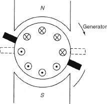
Figure 4.21 EMF Commutation: Method 1
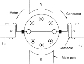
Figure 4.22 EMF Commutation: Method 2
- They make commutation sparkle and ensure automatic neutralization of reactance voltage.
- They neutralize the cross-magnetizing effect of the armature reaction.
4.21 EQUALIZER RINGS
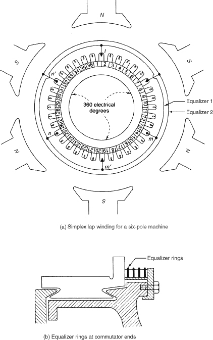
The asymmetrical field or pole system or eccentric armature bearings causes asymmetry between the pole fluxes of the machine. Since in wave winding the winding elements of each parallel path are distributed under all poles of the machine, this effect of flux asymmetry has no effect on the magnitude of emfs induced in the individual circuit of a simple wave winding. But this flux asymmetry has a different effect in lap winding. In this case, the winding elements belong to an armature path, that is, only two adjacent poles. Due to this flux asymmetry, the emfs of the individual flux paths are no longer equal. The points of the winding, which were in-phase points under conditions of symmetry, are no longer in phase. The circulating current flows through these brushes because some of these points are connected by the brushes of the same polarity. In this case sparking can occur if the individual brushes are overloaded. Some in-phase points of the winding having no voltage difference under complete symmetry are tied together by the equalizer connections of negligible resistance. The flow of the alternating current through these windings results in the improvement of commutation and also gives additional heating losses. Equalizer connections are applied to the multipole lap windings and to the wave winding such as duplex, triplex wave windings and so on, having more than two parallel paths. Figure 4.23(a) shows the diagram of a simplex lap-winding for a six-pole machine, whereas Figure 4.23(b) shows equalizer rings at the commutator end.
4.22 CHARACTERISTICS OF DC GENERATORS
Important characteristics of a DC generator are as follows:
- No-load saturation characteristic (E0/If): It is also called open-circuit characteristic or magnetic. It gives the relation between the no-load generated emf in armature (E0) and the field or exciting current (If). This characteristic is same for the separately excited and the selfexcited generators.
- Internal characteristic (Eg/Ia): It practically gives the relation between the emf (Eg) actually induced in the armature conductors (after considering the demagnetizing effect of armature reaction) and armature current Ia. It is also known as total characteristic.
- External characteristic (V/Ia ): It shows the relation between the terminal voltage Vt and the load current I. It is also called performance characteristic or sometimes voltage regulating curve.
4.23 SEPARATELY EXCITED GENERATORS
Figure 4.24 shows a separately excited generator. The field coil is being excited separately.
In Figure 4.24, the field circuit is provided with variable excitation. The armature terminals are connected to the load through a two-pole main switch. A voltmeter is connected across the armature and an ammeter is connected in series with the field coil.
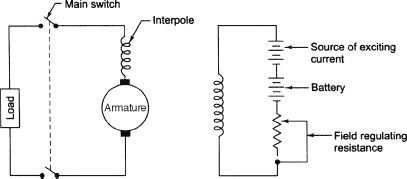
Figure 4.24 Separately Excited Generator
4.23.1 No-load Saturation Characteristic
- The generator is run at a constant speed with the two-pole switch kept open.
- The excitation of the armature is varied and the readings of the ammeter and voltmeter are noted.
- The plot of voltmeter reading and ammeter reading gives the open-circuit characteristic of a separately excited generator shown in Figure 4.25. This is also called magnetization curve.
- During reading of ammeter and voltmeter, it is observed that voltmeter gives a reading at the zero value of field excitation current. This is due to a small amount of permanent magnetism in field poles. This is called residual magnetism, which is usually sufficient to produce 2 to 3 per cent of normal terminal voltage. In some special cases it is purposely increased to 10 per cent or more.
- The first part of the curve is approximately straight and in this zone the flux produced is proportional to the current. But after a certain point, the saturation of iron becomes perceptible and the curve departs from a straight line.
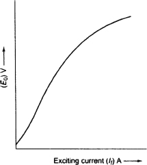
Figure 4.25 Open-circuit Characteristic
4.23.2 Internal and External Characteristic
(or Load Characteristic)
Figure 4.26 shows the external characteristic or load characteristics for a separately excited generator. External characteristic or total characteristic is most important because it gives the way in which the terminal voltage varies with the variation of load current from zero to full-load value. The speed of rotation and the excitation current are kept constant. Voltage drop between the no-load characteristic and external characteristic at a particular load current is due to the following voltage drops:
- Armature reaction, which has demagnetizing effect on the field.
- Resistance drop.
To obtain the internal characteristic, the resistance drop for a few values of current is added to the voltage shown by the external characteristic. The vertical distance between the internal characteristic and no-load voltage represents the effect of armature reaction. The voltage drop across the load resistanceis IR, where R is the load resistance and I is the current. If V is plotted for different values of I, it gives a straight line (OL). The point of intersection of OL and the external characteristic gives the load current and terminal voltage.
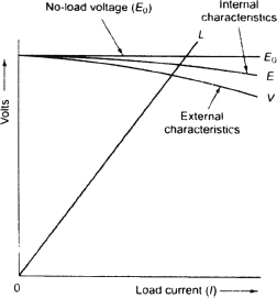
Figure 4.26 Load Characteristic of a Separately Excited Generator
4.24 NO-LOAD CURVE FOR SELF-EXCITED GENERATORS
The field winding of the generator is at first disconnected. It is excited from external DC source, and the excitation current is varied through the rheostat. The armature is rotated at a constant speed (say N rpm). Figure 4.27 shows the circuit connection. The readings of the voltmeter (V) and the ammeter (A) are v noted and are plotted, as shown in Figure 4.28. At zero value of excitation current, the initial value of emf is OD. Slight curvature at the lower end is due to magnetic inertia. The first part of the curve is practically straight because reluctance of the iron path is in negligible order at low flux density. So, the flux and regulator generated emf are proportional to the exciting current. Figure 4.27 Circuit Connection Permeability (μ) is small and reluctance of iron path is large at high flux densities and the straight-line relation between E and I f is not satisfied.
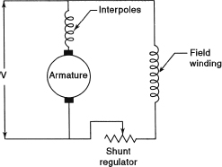
Figure 4.27 Circuit Connection
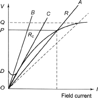
Figure 4.28 No-load Characteristic of Self-excited Generator
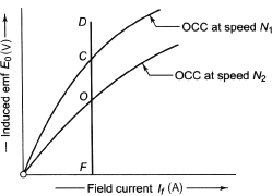
Figure 4.29 OCC for Different Speeds
To get the critical resistance for a shunt generator, the field winding is connected in parallel to the armature and the machine is run as a shunt generator. Since some initial emf exists due to residual magnetism in the poles, current will be generated. This current, during their flow through the field coils, strengthens the magnetism of the poles which increases the pole flux. Hence, the generated emf is further increased. The mutual reinforcement of emf and flux is continued till equilibrium is obtained at some point P (say) in Figure 4.28.
The voltage for which the machine is built up is OP for field resistance R. For a resistance smaller than R (OA), the voltage OQ is slightly greater than OP. For higher value of R, the machine will build up a voltage less than OP. For OC the resistance represented by the tangent of the curve is called the critical resistance of the machine. For OB, the line does not cut the curve, the machine obviously fails to build up or to excite. To calculate the critical resistance, the data are plotted and the open circuit characteristic (OCC) is obtained. A tangent is drawn at the initial position. The slope of the tangent gives the critical resistance. To draw the OCC at different speeds, the OCC for a given speed is obtained first for a speed say, N1.
![]()
From Figure 4.29, if If = OF and E1 = FC, the new value of voltage for the same If at speed N2 is given by ![]() In this way one point is located. Similarly, other points of the no-load curve can be located.
In this way one point is located. Similarly, other points of the no-load curve can be located.
Example 4.9 The magnetization curve of a DC shunt generator at 1,500 rpm is as follows:
![]()
For this generator, find (i) the no-load emf for a total shunt field resistance of 100 Ω, (ii) the critical field resistance at 1,500 rpm and magnetization curve at 1,200 rpm and (iii) the open-circuit voltage for a field resistance of 100 Ω.
- From the given data the OCC is drawn. This OCC is for a speed of 1,500 rpm. The shunt field resistance line (R = 100 Ω) is drawn joining the origin (0, 0) and the point (1 A, 100 V). The point of intersection of the OCC and the resistance line is F, and the voltage corresponding to the point F is 227.5 V. Therefore, no-load emf is 227.5 V
- The tangent OE to the OCC at the origin is drawn. The critical resistance = slope of line OE = 225/1.5 = 150 Ω.
- The induced emf for field currents for 1,200 rpm is (1,200/1,500) or 0.8 times the values given at 1,500 rpm. The data of magnetization curve corresponding to 1,200 rpm are shown below:
![]()
The OCC is shown in Figure E4.1.
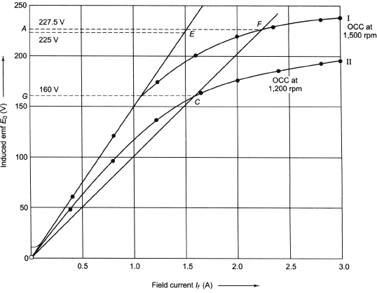
Figure E4.1
Example 4.10 The open-circuit characteristic of a separately excited DC generator driven at 1,000 rpm is as follows:
![]()
If the machine is connected as a shunt generator and driven at 1,000 rpm and has a field resista ce of 100 Ω, find (i) the open-circuit voltage and exciting current, (ii) the critical resistance and (iii) the resistance to induce 115 V on open circuit.
Solution
- From the given data the OCC is drawn and shown in Figure E4.2. This OCC is for a speed of 1,500 rpm. The shunt field resistance line (R = 100 Ω) is drawn joining the origin (0, 0) and the point (1 A, 100 V). The point of intersection of the OCC and the resistance line is F and the voltage corresponding to the point F is 100 V. Therefore, no-load emf is 100 V.
- The tangent OE to the OCC at the origin is drawn. The critical resistance = slope of line OE = 12/0.8 = 150 Ω.
- From Figure E4.2, the exciting field current corresponding to open-circuit voltage 115 V is 1.4 Ω.
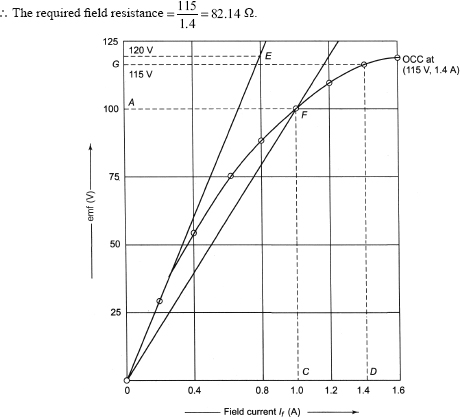
Figure E4.2
4.25 ADVANTAGES AND DISADVANTAGES OF SEPARATELY EXCITED GENERATORS
In separately excited DC generators, the reduction in terminal voltage is due to the IuRu drop, which is 2 to 5 per cent, and hence it is very small. The terminal voltage remains more or less constant with load current compared to the other generators. Separately excited generators are very widely used at the distribution point where constant voltage is required.
4.26 VOLTAGE BUILD-UP OF SHUNT GENERATOR
The shunt generator is allowed to build up at first before loading it. Due to the presence of residual magnetism in the poles, a small emf is generated, which circulates a small current in the field circuit. If the field is properly connected to the armature, this circulation of current further increases the pole flux, which in turn increases the generated emf and this continues until the full open-circuit emf is generated. Any improper connection of field coil to armature may destroy the residual magnetism. The generated emf in the armature supplies the ohmic drop and overcomes the self-induced emf in the field coil. For the current OE shown in Figure 4.30, EF goes to supply the ohmic drop and the rest of FG overcomes the self-induced emf. For the field current OX, the generated emf is fully utilized to supply the ohmic drop and cannot overcome the self-induced emf. There is no energy stored in field poles and no further increased interpole flux and generated emf. The maximum voltage to which the machine builds up for the given shunt field resistance (R) represented by the line OA is XB. For smaller resistance of field coil, the machine will build up to a somewhat higher value. If the shunt field is greater than the critical resistance value, the machine will not be able to build up. The critical resistance is represented by the line OQ.
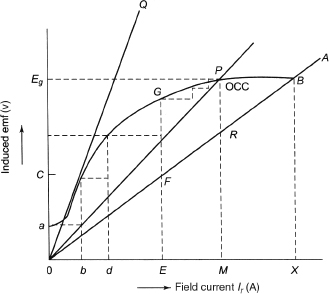
Figure 4.30 Voltage Build-up of a Shunt Generator
4.27 CONDITIONS FOR BUILD-UP OF SHUNT GENERATOR
The following conditions must be met to build-up of a shunt generator:
- Generator poles must have residual magnetism.
- The shunt field coils must be properly connected to the armature for a given direction of rotation of armature.
- The resistance of shunt field coil must be less than the critical resistance if excited on open circuit.
- The shunt field resistance must be greater than some minimum value if excited on load.
4.28 REASONS FOR FAILURE TO BUILD-UP OF SHUNT GENERATORS
Some probable causes for the failure of shunt generators to build up voltage are as follows:
- No residual magnetism.
- Field connection is reversed.
- Field circuit resistance is too high.
- Open field circuit connection.
- Dirty commutator.
4.29 EXTERNAL CHARACTERISTIC OF SHUNT GENERATOR
In a shunt generator, the field circuit is directly connected across the armature. The terminal voltage decreases due to an increase in the generator current. The following three factors are responsible for the decrease in terminal voltage:
- Armature circuit resistance: The generator has armature resistance, and hence voltage drop occurs. This resistance includes the resistance of (i) the copper conductors of the armature windings, contact resistance between the brushes and the commutator and (iii) the brushes themselves.
- Armature reaction: Due to the flow of currents through the armature conductors, a flux known as armature flux surrounds these conductors. The direction of this flux is such that it reduces the strength of the main flux, and hence reduces the generated voltage as well as the terminal voltage.
- Reduction of field current: The decrease of the terminal voltage decreases the field current because the field coil is connected across the armature. This decrease in the field current decreases the field flux, which in turn further decreases the terminal voltage.
Figure 4.31 shows the circuit connection of a shunt generator. The shunt generator is at first excited on no-load and its full open-circuit voltage is obtained. Gradually the load is applied and its terminal voltage decreases due to IaRa drop. The readings of armature terminal voltage and the load current are recorded. Using a rheostat, the field current is kept unaltered. The readings of terminal voltage and load current are plotted and external characteristic is obtained. Usually the external load-voltage characteristic decreases with application of load only to a small extent up to its rated load value or current value.
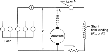
Figure 4.31 Circuit Connection of a Shunt Generator
The portion ij of Figure 4.32 is called the working part of this curve, and any decrease in load resistance increases the load current resulting in a comparatively small additional voltage drop over this working part, which holds good until the breakdown point j is reached. Figure 4.32 shows that if load current is increased by decreasing the load resistance beyond the breakdown point j, it results in a rapid decrease in terminal voltage. This happens because any further decrease in the load resistance at the point i causes the current to become greater than OX (rated current) of Figure 4.32. This causes severe armature reaction and increases the armature voltage drop and decreases the terminal voltage. Therefore, over the part jlk any decrease in load resistance results in a less load current and Ohm's law seems to be inapplicable. The curve jlk turns back and cuts the load current axis and the terminal voltage becomes zero.
Figure 4.33 shows the external characteristic due to varying excitation of field coil.
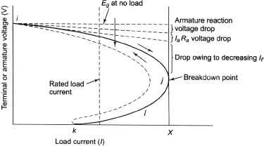
Figure 4.32 External Characteristic of a Shunt Generator
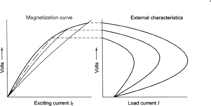
Figure 4.33 Effect of Varying Excitation
4.30 VOLTAGE REGULATION
The degree of change in armature terminal voltage due to application of load is known as voltage regulation. If there is little change in voltage from no load to full load, the generator is said to have good voltage regulation. If there is appreciable change in voltage from no load to full load, the generator is said to have poor voltage regulation.
The change in load voltage from no load to full load expressed as a percentage of the rated terminal voltage is known as per cent voltage regulation.
Per cent voltage regulation ![]() where Vnl is the no-load voltage and Vfl is the full-load voltage.
where Vnl is the no-load voltage and Vfl is the full-load voltage.
4.31 INTERNAL OR TOTAL CHARACTERISTIC
The following procedure is followed to determine the internal characteristic from the external characteristic shown in Figure 4.34.
- External characteristic is drawn from the available data.
- The shunt field resistance line (OL) and armature resistance line (OM) are drawn.
- Any point F is taken on the external characteristic.
- From F, a vertical line and horizontal lines intersecting x-and-axes, respectively are drawn. These lines are FC and FA, respectively.
- A point D is taken on x-axis, where CD = AB represents the shunt field current (Ish).
- A vertical line DE is drawn from D and it is extended so that it intersects extended AF at H.
- A point G is taken on the line DH extended so that HG = DE = IaRa .
- A number of points are taken on the external characteristic, and the corresponding points lying on internal characteristic are obtained.
- A curve is drawn passing through these points and this represents the external characteristic.

Figure 4.34 Determination of Internal Characteristic from External Characteristic
4.32 EXTERNAL CHARACTERISTIC AND INTERNAL
CHARACTERISTIC FROM OCC
The external characteristic of a shunt generator can be obtained directly from its no-load saturation curve. The following two cases are taken into account:
- Neglecting armature reaction.
- With armature reaction.
4.32.1 Neglecting Armature Reaction
- From the given data the OCC is plotted, as shown in Figure 4.35.
- A shunt field resistance line (OS) is drawn that meets OCC at the point A.
- A horizontal line intersecting the y-axis at B is drawn from the point A. OB is the maximum no-load or open-circuit voltage.
- A point L is taken on OCC, and an ordinate LMN is drawn, which intersects the field resistance line and x-axis at M and N, respectively. LN, MN and LM represent the generated emf, the terminal voltage and voltage drop in armature, respectively.
- From points L and M, horizontal lines are drawn that cut the vertical axis at points D and E, respectively.
- An armature resistance line OC is drawn.
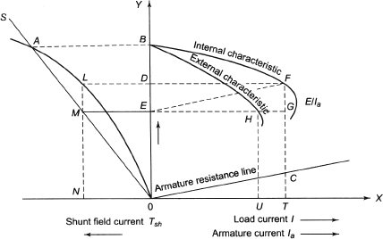
Figure 4.35 Determination of External and Internal Characteristic from OCC
- A line EF parallel to line OC, cutting line LD extended at F is drawn from point E. The point F is lying on the internal characteristic.
- Other points can be obtained and internal characteristics be drawn through these points.
- A vertical line is drawn from the point F, which intersects the extended line ME at the point G and x-axis at a point T. The point G lies on the curve representing the relation between armature current and terminal voltage because FG = LM = CT.
- TU is the shunt field current and it is equal to ON (different scale). OU represents the load current corresponding to the armature current represented by OT and terminal voltage OE.
- A vertical line intersecting line EG at H is drawn from U. The point H lies on the external characteristic.
- The other points can be obtained similarly. The curve through these points gives external characteristic.
4.32.2 With Armature Reaction
In this case, the voltage drop due to armature reaction, in addition to voltage drop due to armature resistance, is considered.
A right-angled triangle lmn is drawn such that ln and mn represent the voltage drop in armature and shunt field current, respectively. The triangle lmn is known as the drop reaction triangle. All the processes in Section 4.32.1 are repeated with the following modifications to draw the internal and external characteristics.
- A point L is taken on the OCC, and a line LM parallel to lm is drawn and the triangle LMN is completed. The vertical lines are drawn from the points L and M, which cut x-axis at points N´ and MM, respectively. LN´, MM´, LN and ON represent the generated emf, terminal voltage, the voltage drop in armature due to armature resistance and the shunt field current to induce an emf represented by LN´, respectively. N´M´ represents the increase in shunt field current to counteract the demagnetizing effect.
- TU is the shunt field current that is equal to ON´ (on different scale), and OU represents the load current corresponding to the armature current represented by OT and terminal voltage MM´.
4.33 EFFECT OF BRUSH SHIFT ON THE TERMINAL VOLTAGE
When the brush axis coincides with the GNA, the terminal voltage of the generator gradually decreases with the increase in load. The armature mmf acts on the GNA and it is normal to the field mmf (M)f. Hence, there is no demagnetizing effect in the main field mmf. If the brush axis is shifted by an angle θ from the geometrical neutral axis in the direction of rotation shown in Figure 4.36(a), the generator terminal voltage decreases more rapidly shown by curve 2 in Figure 4.36(c), which is solely due to the armature reaction having a component Ma sinθ opposing Mf shown in Figure 4.36(a). The resultant mmf in the air gap decreases. This reduces the resulting induction emf, and hence the terminal voltage also decreases, which is more pronounced with an increase in the load current.
Figure 4.36(b) shows the case when the brush is shifted backwards having the armature mmf component Ma sinθ, acting in the direction of the main field mmf (Mf). This reinforces Mf and hence the flux in the air gap increases, resulting in the generated emf on the load. Hence, the terminal voltage also increases, as shown in curve 3 of Figure 4.36(c). This is not preferred because it leads to bad commutation.
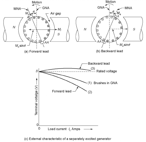
Figure 4.36 Effect of Brush Shift on the Terminal Voltage
4.34 SERIES GENERATOR
The OCC of a series generator is drawn in a manner similar to that of the shunt generator. Figure 4.37 shows the circuit diagram for series generator to obtain the OCC. Curve 1 is the OCC for series generator, as shown in Figure 4.38.
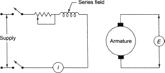
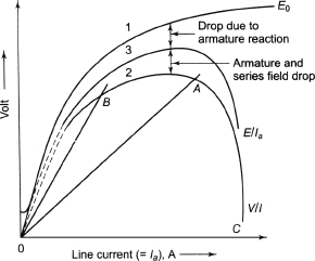
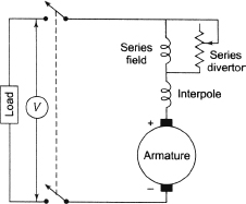
Figure 4.39 Circuit for Loading a DC Series Generator
Figure 4.39 shows the circuit for loading a series generator. Curve 2 of Figure 4.38 is the external characteristic of DC series generator.
To get the internal characteristic (curve 3 of Figure 4.38), the voltage drop Ia(Ra + Rse) is added to the external characteristic curve, where Ra and Rse are the armature resistance and the series field resistance, respectively.
4.35 COMPOUND GENERATOR
Figure 4.40 shows the connection diagram for a compound generator.
Figure 4.41 shows the current directions in the series and shunt generators.
The external load voltage characteristics of cumulative and differential compound generators are shown in Figure 4.42.
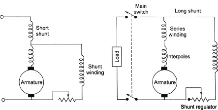
Figure 4.40 Connection Diagram for Compound Generator

Figure 4.41 Current Directions in Series and Shunt Generators
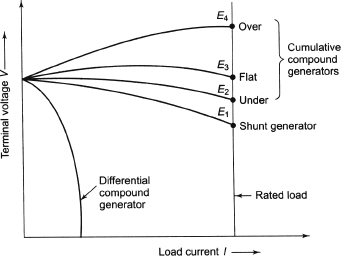
Figure 4.42 External Load Characteristics of Cumulative and Differential Compound Generators
The following definitions are useful:
- Over-compound generator: In over-compound generator, the terminal voltage rises with the application of load so that its full-load voltage exceeds its no-load voltage. The voltage regulation is negative.
- Flat-compound generator: In flat-compound generator, the full-load voltage and no-load voltage are equal. The voltage regulation is zero.
- Under-compound generator: In under-compound generator, the full-load voltage is less than no-load voltage. The voltage regulation is positive.
4.36 PARALLEL OPERATIONS OF DC GENERATORS
Parallel operation of DC generators is required to meet the extra load demand. It is very difficult to meet the extra load demand by a single generator, or it is not possible to give supply when one generator is out of order. The following reasons are given for paralleling of DC generators:
- Reliability: The generators that are sources of power are primary safety items, and hence paralleled for reliability.
- Continuity of service: Continuity of power supply is most important to satisfy the customers. If a single generator is used, it is difficult to give supply during its breakdown.
- Efficiency: The load is not uniform. It is maximum during the day and minimum during the night. The generators must operate most efficiently during full-load condition. It is preferred to use a single generator during light load.
- Maintenance and repair: Inspection of generators is carried out frequently to check any possibility of future breakdown. This is possible only when the generator is at rest and other generators take care of the load. During breakdown stage of a generator, it is repaired and other generators take over and meet the load requirements.
4.37 REQUIREMENTS FOR PARALLELING DC GENERATORS
Paralleling DC generators is required mainly for the following two types of situations:
- Paralleling of shunt generators for the same or varying sizes.
- Paralleling of compound generators of the same and varying sizes.
For successful paralleling of DC generators, the voltage of each parallel unit must be equal. During paralleling of DC generators the following conditions must be satisfied to make an agreement with Kirchhoff's current law if the generated voltage of each generator is not the same:
- If the developed internal generated voltage is greater than the voltage at the paralleling point, generating action will take place and the unit will supply current to the load.
- If the developed internal generated voltage is equal to the voltage at the paralleling point, the generator is said to be ‘floating’ on the line.
- If the developed internal generated voltage is less than the voltage at the paralleling point, it will operate in motoring mode, drawing current from the paralleling point.
The following conditions must be satisfied for the paralleling of DC generators:
- The polarities of the generators must be identical.
- The terminal voltages must be the same.
- The change of voltage with the change of load must be of the same character.
- The prime movers driving the armatures of the generators must have similar and stable rotational characteristics.
A positive regulation generator should not be combined with a negative regulation generator because in this case circulating current will dominate. An exact match characteristic in this case is very difficult to achieve.
4.38 PARALLEL OPERATION OF SHUNT GENERATORS
Figure 4.43 shows parallel operation of DC generators. Generator 1 is connected to the bus bars and supplies the load. Generator 2 is required to be connected in parallel with generator 1 to supply a part of the load.
The following procedures are followed during paralleling:
- Generator 2 is speeded up to the rated voltage by means of a prime mover. The switch S2 is closed and a voltmeter is placed across the open switch S1.
- The excitation of the generator is changed until the reading of the voltmeter connected across the open switch S1 is zero. At this point, the voltage of generator 2 is the same as the voltage of generator 1.
- The switch S1 is closed and generator 2 is in parallel with generator 1. Generator 1 is supplies the entire load, whereas generator 2 is in floating stage.
- It is required to shift load from generator 1 to generator 2. The field rheostat resistance of generator 1 is cutting in, whereas the field rheostat resistance of generator 2 is cutting out. In this way any degree of load can be shifted from generator 1 to generator 2. If the entire load is shifted from generator 1 to generator 2, the switch S is opened to remove generator 1 from the line.
- During shifting the load from one generator to another, the reading of A1 and A2 should be observed very carefully.
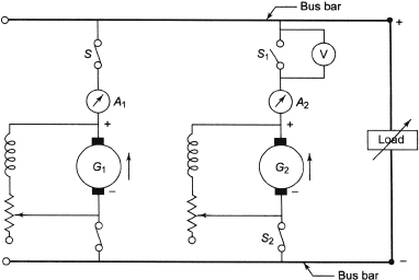
Figure 4.43 Two-shunt Generators in Parallel
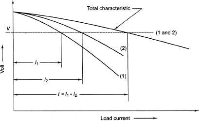
Figure 4.44 Characteristics of Shunt Generators in Parallel
Due to the drooping characteristic of shunt generators, these generators are well suited for parallel operation. Figure 4.44 shows the characteristics of two shunt generators 1 and 2. Generator 1 has more drooping characteristic than generator 2. Neglecting very small voltage drop across the connecting leads, the terminal voltages of the two generators connected in parallel must be identical. For a common terminal voltage, generator 1 supplies the load I1 and generator 2 supplies the load I2. Therefore, the generator having more drooping characteristic carries the smaller load.
A condition may arise that temporarily causes generator 1 to take more than its share of load. This condition might arise for a temporary increase in the speed of its prime mover, or due to momentary change of load on the system. After restoring the normal condition, generator 1 would tend to operate at some point a on its characteristics. This results in a drop in its terminal voltage, which tends to make it take less load. Moreover, at the time generator 1 takes more load, generator 2 must take less load. The total load remains constant and generator 2 tends to operate at some point b on its characteristics. This raises its terminal voltage and causes it to take more load. Therefore, any tendency of one generator to take more than its share of load results in changes of voltage in the system which opposes this tendency. Hence, the shunt generators in parallel may be said to be in stable equilibrium. The reaction of the system is such as to hold the generators in parallel.
When the machines have unequal emfs on no load, the distribution of currents between them can be determined analytically as follows:
| Let, | R be the resistance of the combined load, |
| E1 be the emf of generator 1, | |
| E2 be the emf of generator 2, | |
| Vt be the terminal voltage of the two machines, | |
| R1 be the armature resistance of generator 1 and | |
| R2 be the armature resistance of generator 2. |
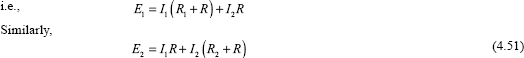
We have
![]()
![]()
![]()
![]()
Solving Equations (4.50) and (4.51), we have
![]()
![]()
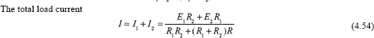
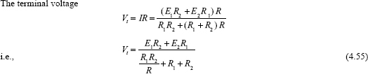
From Equation (4.55) the following cases can be drawn.
Case I: When the load is open circuited, R = ∞and V t = V 0 = the no-load terminal voltage.
![]()
From Equations (4.52) and (4.53), we have I = I c (Circulating current)
![]()
Case II: When load is short circuited, R = 0.
From Equation (4.54), we have
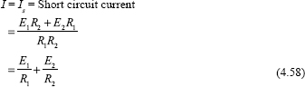
DC shunt generators having drooping external characteristic perform well when they are connected in parallel. If any fault occurs in any prime mover and the speed gets reduced, there will be a reduction in the emf of this machine. The second machine will be overloaded without showing any tendency for unstable operation.
4.39 PARALLEL OPERATION OF SERIES GENERATORS
These generators are not usually operated in parallel. They are put in parallel for electric traction purposes to provide electric breaking of motors. Figure 4.45 shows two series generators put in parallel operations under normal working conditions, that is, on the rising portion of external characteristics. If the load current shared by machine 1 is increased, the induced emf will also increase, which will lead machine 1 to share the greater load current and it relieves the other machine. This causes the emf of machine 1 to increase and the emf of machine 2 to decrease continuously. When the emf of the machine 2 is less than the terminal voltage, it receives current and its polarity gets reversed, which makes the emfs of the two machines to act in series around the load circuit of the generators having a very low resistance virtually acting as a short circuit on the two machines.
If the field coils are connected in parallel using equalizing bus bars having negligible resistance shown in Figure 4.45(a), this will make the currents in the field windings of two machines equal. The increase in the current of generator 1 leads to an increase in the current of generator 2; hence, the emf of generator 2 also increases preventing machine 1 to share more load. There is no tendency to relieve machine 2 from sharing its load as in the previous case.
If there is any fault developed by the prime mover of machine 2 and is not driving the machine 2, machine 2 is slowed down only until its emf reduces to a value less than its terminal voltage. Therefore, machine 2 acts as a separately excited motor due to the equal currents in the field windings because they are connected in parallel and will continue to run on light load.
Figure 4.45(b) shows that the field coils are cross-connected when the series motors are connected in parallel. In case of any increase in the current of the armature of generator 1, the increased current flows through the field coil of generator 2. This increases the emf of machine 2, which opposes the change in load sharing trying to stabilize the operation of the two machines at the original operating point itself or near to it. This gives more positive and better operation than in the case shown in Figure 4.45(a).

Figure 4.45 Series Generators in Parallel
4.40 PARALLEL OPERATION OF COMPOUND GENERATORS
The under-compound generators have drooping characteristic, and hence it is possible to operate them in parallel without any difficulty. The level- and over-compound generators cannot be operated in parallel satisfactorily.
If they are operated in parallel, inherently they are unstable. Any increase in the load current in one generator strengthens the field flux, and hence increases the generated voltage. It causes the machine to take up still greater load. For a fixed load, the other generator sheds part of its load, which results in the weakening of its field and it sheds more load. If this process is continued cumulatively, one machine can run the entire load and it can drive the other as a differentially compounded motor at an excessively high speed.
To get stable operation of compounded generators in parallel, the series field windings are connected in parallel using equalizers that are low-resistance connections. These are usually provided in the form of another bus bar on the switch board, as shown in Figure 4.46.
Example 4.11 Two DC shunt generators operating in parallel deliver a total current of 250 A. One of the generators is rated 50 kW and the other 100 kW. The voltage rating of both machines is 500 V and have regulations of 6 per cent (smaller one) and 4 per cent, respectively. Assume linear characteristic. Determine (i) the current delivered by each machine and (ii) the terminal voltage.
Solution
![]()
Full-load voltage drop = 0.06 x 500 = 30 V.
Voltage drop per ampere of current supply = 30/100 = 0.3 V/A.
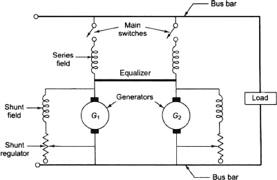
Figure 4.46 Two-compounded Generators in Parallel
For 100 kW generator:
![]()
Full-load voltage drop = 0.04×500 = 20 V
Voltage drop per ampere of current supply = 20/200 = 0.1 V/A.
Let 50 kW and 100 kW generators supply current I1 A and I2 A, respectively at the terminal voltage of Vt V
Therefore, we can write the following equations:
![]()
![]()
![]()
Solving Equations (1) and (2), we have
I1 = 62.5 A and I2= 187.5 A.
Substituting I1 = 62.5 A in Equation (1), we have
Vt= 500 - 0.3 * 62.5 = 481.25 V
Example 4.12 Two DC shunt generators with emfs 120 V and 115 V, armature resistances of 0.05 Ω and 0.04 Ω and field resistances of 20 Ω and 25 Q, respectively are in parallel, supplying a total load of 25 kW. How do they share the load?
Solution
Let the terminal voltage of the generators be Vt
Substituting I 1 in Equation (1), we have
4.41 USES OF DC GENERATORS
- Separately excited generators: This type of generators have special applications such as electroplating, electrorefining of materials because separate supply is required for field excitation.
- Shunt generators:This type of generators are used in battery charging and ordinary lighting purposes.
- Series generators: This type of generators is used commonly as boosters on DC feeders, as current generators for welding and arc lamp.
- Cumulatively compounded generators: This type of generators is used for domestic lighting purposes and to transmit energy over long distances.
- Differential compound generators: This type of generators is rarely used. They are used for special applications such as electric arc welding.
4.42 INDICATIONS OF AN OVERLOADED GENERATORS
The following are the indications of overloading:
- Excessive sparking at brushes.
- Overheating of the armature and other parts of the generator.
4.43 CAUSES OF OVERLOADING
The following are the causes of overloading:
- Excessive voltage due to over excitation of field magnets or too high speed of the prime mover.
- Excessive current due to bad feeding of load or short circuit/ground in the generator itself or in the external load circuit.
- Reversal of polarity.
4.44 CAUSES OF SPARKING AT BRUSHES OF A DC MACHINE
The following are the most probable causes:
- Inadequate pressure on brushes.
- Incorrect position of the brushes.
- Unequal brush spacing.
- Carbon brushes short circuit more segments at time.
- Brushes not properly bedded.
- Worn out brushes.
- Wrong grade of brushes.
- Commutator is not fully round.
- Rough commutator surface.
- Projection of intersegment micas.
- Segments short circuited by carbon filling.
- Oil and dirt on commutator surface.
- Play in the armature.
- Earth fault in armature windings.
- Overloading of armature.
- Reversed interpole polarity.
4.45 CAUSES OF EXCESSIVE HEATING OF GENERATOR ON RUNNING
The following are the probable causes of excessive heating of generator on running:
- Sparking at the brushes.
- Weak insulation in the lamination.
- Short circuit in field and armature winding.
- Defective bearing.
4.46 CAUSES OF HEATING OF ARMATURE
The following are the causes of heating of armature:
- Eddy current.
- Moisture absorption in insulation of armature winding.
- Unequal strength of field poles.
- Operating at above rated voltage and below normal speed.
4.47 CAUSES FOR ABNORMAL SOUND IN DC GENERATOR
The following are the most probable causes for abnormal sound in DC generators:
- Unequal resistances of armature or field coils.
- Loose fitting of field cores with yoke or frame.
- Improper fitting of end covers.
- Loose fitting of foundation.
4.48 REASONS FOR RAPID BRUSH WEAR IN A DC MACHINE
The following are the causes for the rapid brush wear in DC machine:
- Rough surface of the commutator.
- Imperfect contact with the commutator.
- Excessive pressure of the brushes.
- Severe sparking.
ADDITIONAL SOLVED PROBLEMS
Example 4.13 A DC shunt generator having terminal voltage 250 V, delivers load current 195 A. The armature and shunt field resistances are 0.05 Ω. and 50 Ω, respectively. Calculate (i) the shunt field current, (ii) the armature current, (iii) the generated emf in armature and (iv) the load resistance.
Solution

Example 4.14 A long-shunt compound DC generator having terminal voltage 300 V delivers a load current of 60 A. The armature, series field and shunt field resistances of the generator are 0.05 Ω, 0.04 Ω. and 200 Ω, respectively. Calculate the generated voltage and the armature current if the contact voltage drop per brush is 1 V.

The armature current and the generated emf are 61.5 A and 307.535 V, respectively.
Example 4.15 A short-shunt compound generator having terminal voltage 250 V delivers a load current of 40 A. The armature, series field and shunt field resistances are 0.05 Ω, 0.04 Ω and 100 Ω, respectively. Calculate the generated emf and the armature current if there is voltage drop of 1 V per brush.
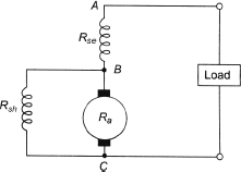
Solution
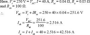
Eg=VBC+ IaRa+2× 1=251.6+42.516× 0.05+2=255.73 V
Therefore, the armature current and the generated voltage are 42.516 A and 255.73 V
Example 4.16 An eight-pole lap-wound DC generator having 760 conductors, and a useful flux of 35 mWb/pole is driven at 500 rpm. Calculate the generated emf.
Solution
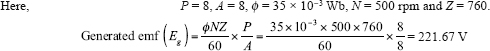
Example 4.17 The useful flux of an eight-pole lap connected DC generator is 40 mWb. Determine the number of conductors on the armature periphery if it has no-load voltage of 250 V and rotates at a speed of 500 rpm.
Solution
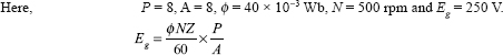
![]()
Example 4.18 An eight-pole lap-wound DC generator has 70 slots in its armature with 22 conductors per slot. The ratio of pole arc to pole pitch is 0.64. The diameter of the bore of the pole shoe is 0.48 m. The length of the pole shoe is 0.28 m. The air gap flux density is 0.32 Wb/m2 and the generated emf in the armature is 400 V Find the speed of the generator.
Solution
Here, P = 8, number of slots = 70, conductors per slot = 22.
Therefore, the total number of conductors = 70 × 22 = 1,540.
The ratio of pole arc to pole pitch = 0.64.
Diameter of the bore of the pole shoe = 0.48 m and the length of the pole shoe = 0.28 m
Air gap flux density = 0.32 Wb/m 2
emf generated ( Eg ) = 400 V
Speed of rotation ( N ):
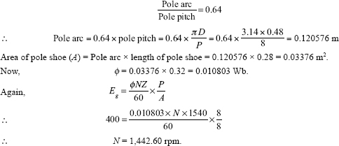
Example 4.19 A four-pole DC shunt generator having 676 wave-connected armature conductors runs at a speed of 600 rpm and supplies a load resistance of 10 Ω at a terminal voltage of 200 V. The armature and field resistances are 0.34 Ω. and 100 Ω, respectively. Calculate the following:
- The armature current.
- The generated emf.
- The flux/pole.
Solution
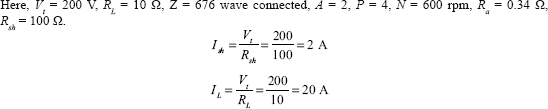
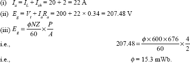
Example 4.20 A six-pole DC shunt generator supplies full-load current at a terminal voltage of 250 V The armature and field resistances are 0.04 Ω and 100 Ω, respectively. It runs at a speed of 1,000 rpm and has 700 lap-connected conductors. The voltage across armature resistance is 7.2 V. Find the following: (i) the load current, (ii) the emf generated and (iii) the flux/pole. Neglect brush contact drop.
Solution
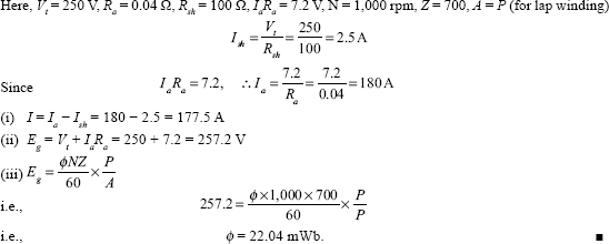
Example 4.21 A six-pole, long-shunt, wave-connected DC generator supplies 22 kW at terminal voltage of 220 V. The armature, series field and shunt field resistances are 0.05 Ω, 0.04 Ω and 110 Ω, respectively. Find the armature current and the generated emf. Assume 1 V per brush for contact drop.
If the speed of the armature is 1,000 rpm and the flux per pole is 7.8 mWb, calculate the number of conductors of the armature.
Solution
Here, P = 6, power output = 22 kW, Vt = 220 V, Ra = 0.05 Ω, Rse = 0.04 Ω, Rsh = 110 Ω, N = 1,000 rpm, φ = 7.8 × 10⁻³ Wb, contact drop per brush = 1 V, parallel path (A) = 2 due to wave connection of conductors.
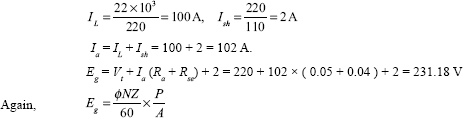
Example 4.22 A six-pole DC shunt generator has the following data:
Field resistance = 120 Ω, armature resistance = 0.8 Ω, number of conductors = 350 (wave connected), flux/pole = 0.02 Wb.
Load resistance across the terminals = 12 Ω, armature rotates at 1,000 rpm. Calculate the power absorbed by the load.
Solution

Example 4.23 A separately excited DC generator has terminal voltage 250 V with constant field excitation. If the load changes from 200 kW to 125 kW, find the percentage reduction in the speed. The armature resistance is 0.015 Ω and the total contact drop at brushes is 2 V. Neglect the armature reaction. The flux and the total number of armature conductors remain constant.
Solution
Terminal voltage (Vt) = 250 V, Ra = 0.015 Ω, total contact drop at brushes = 2 V Since the flux and total number of armature conductors remain constant, we have
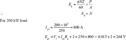
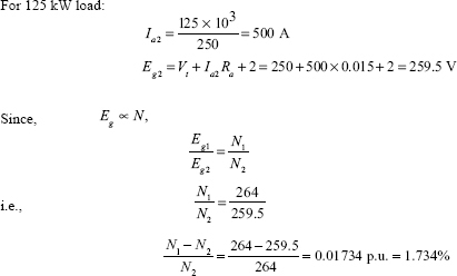
Therefore, reduction in speed is 1.734 per cent.
Example 4.24 A separately excited DC generator having constant excitation supplies power to a constant resistance load. It delivers 150 A at 400 V at a speed of 1,000 rpm. If current is reduced to 100 A, determine the speed. Total contact drop of brush is 2 V Neglect the armature reaction. Armature resistance of the generator is 0.12 Ω.
Ia1 = 150 A, N 1 = 1,000 rpm, Vt = 400 V, Ra = 0.12 Ω, Ia2 = 100 A, total contact drop for brush = 2 V.
The value of load resistance 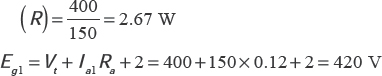
For load current 100 A, the terminal voltage becomes
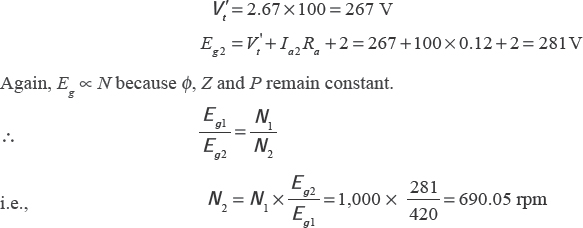
The speed at load of 100 A is 690.05 rpm.
Example 4.25 A long-shunt DC dynamo having terminal voltage of 250 V at 1,000 rpm supplies 25 kW. The resistances of armature, shunt field and series field are 0.04 Ω, 50 Ω and 0.05 Ω, respectively. Calculate (i) Cu-losses, (ii) iron and friction losses and (iii) the torΩue exerted by the prime mover if it has efficiency 89 per cent of the above load.
Solution

(i) Armature Cu-loss ![]()
Series fi eld Cu-loss ![]()
Shunt fi eld Cu-loss ![]()
![]() Total Cu-loss = 441 + 551.25 + 1,250 = 2,242.25 W
Total Cu-loss = 441 + 551.25 + 1,250 = 2,242.25 W
(ii) The output power = 25,000 W
![]()
Total losses = 28,089.89 – 25,000 = 3,089.89 W
![]() Iron and friction losses = 3,089.89 – 2,242.25 = 847.64 W
Iron and friction losses = 3,089.89 – 2,242.25 = 847.64 W
(iii) Let T be the torque exerted by the prime mover.
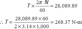
Example 4.26 A 10 kW, six-pole DC generator develops an emf of 200 V at 1,500 rpm. The armature has a lap-connected winding. The average flux density over a pole pitch is 0.9 T. The length and diameter of the armature are 0.25 m and 0.2 m, respectively. Calculate (i) the flux per pole, (ii) the total number of active conductors in the armature and (iii) the torque developed by the machine when the armature supplies a current of 50 A.
Solution
Eg = 200 V, N = 1,500 rpm, P = 6
A = 6 (because generator is lap wound)
L = 0.25 m and d = 0.2 m, B = 0.9 T
(i) If Z = number of conductors, pole pitch ![]()
Angle subtended by pole shoe ![]()
Arc length of the pole shoe ![]()
Area of the pole shoe = 0.130834 × 0.2 = 0.026168 m2
![]() Flux per pole = Flux density × Area of pole shoe
Flux per pole = Flux density × Area of pole shoe
= 0.9 × 0.026168 = 0.0235512 Wb
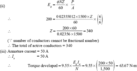
Example 4.27 A 40 kW, 400 V, four-pole DC generator has a two-layer s1mplex lap w1nd1ng rn30 slots w1th 12 conductors 1n each layer. If the brushes are g1ven an actual lead of 10°, calculate the following:
- Demagnet1z1ng AT/pole.
- Cross-magnet1z1ng AT/pole.
- Number of turns per pole on the compensat1ng w1nd1ng 1f the pole arc to p1tch 1s 0.8 and brushes
Solution
Z = 2 × number of slots × conductors/slot = 2 × 30 × 12 = 720
Number of parallel paths (A) = 4.
Brush lead (θm) = 10°
Armature current (Ia) ![]()
Current in each conductor conductor ![]()
(i) Demagnetizing AT/pole:
![]()
(ii) Cross-magnetizing AT/pole:

(iii) Number of turns per pole for compensating winding:
AT pole for compensating winding ![]()
Therefore, the number of turns per pole for compensating winding ![]()
Example 4.28 Two 240V DC generators operate in parallel. The first generator has a terminal voltage of 280 V on no load and 240 V when supplying 40 A. The second generator has a voltage of 300 V when on no load and 240 V when supplying 50 A. Calculate the following:
- The current supplied by each generator.
- The output voltage.
- The output kW of each machine.
The total load current is 60 A.
Solution
- Generator 1:
Voltage drop for 40 A = 280 – 240 = 40 V
Therefore voltage drop per ampere
Generator 2:
Voltage drop for 50 A = 300 – 240 = 60 V
Therefore voltage drop per ampere
Let I1 and I2 be the output currents of generator 1 and generator 2, respectively. Let Vt be the common terminal voltage.
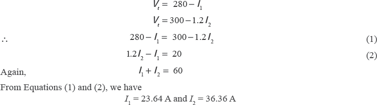
- Output of each generator.
Vt = 280 - I 1 = 280 - 23.64 = 256.36 V
Vt = 300 - 1.2 I 2 = 300 - 1.2 × 36.36 = 256.36 V
- Output of generator 1,
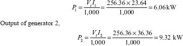
Example 4.29 Two DC shunt generators having armature and field resistances of 0.05 Ω and 100 Ω, respectively are operating in parallel. The emf induced in one machine is 250 V, whereas that in the other is 260 V, supplying a common load of 1,500 A. Calculate the following:
- The terminal voltage.
- The output of each machine.
Eg1 = 250 V and Eg2 = 260 V, Ra = Ra1 = Ra2 = 0.05 Ω and Rsh = 200 Ω, I = 1,500 A. Let Vt the common terminal voltage.
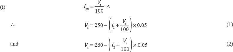
where I1 and I2 are the currents supplied by the generator 1 and generator 2, respectively.
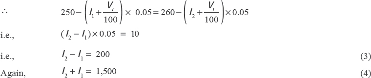
From Equations (3) and (4), we have
I1 = 650 A and I2 = 850 A.
Substituting the value of I1 in Equation (1), we have
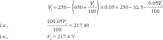
Therefore, the terminal voltage is 217.4 V.
(ii) Output of generator 1,
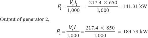
SIGNIFICANT POINTS
- Shunt Generator:
Ia = IL + I sh
Eg = Vt + IaRa
- Series Generator:
Ia = Ise = IL
Eg = Vt + Ia(R a +Rse )
- Induced emf:

- Efficiency:
- Mechanical efficiency:
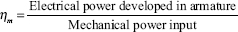
- Electrical efficiency:
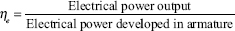
- Commercial or overall efficiency:
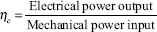
- Maximum efficiency:
Generator efficiency is maximum when
Constant loss = Cu-loss or variable loss.
The load current at which maximum frequency occurs is given by

- Demagnetizing and cross-magnetizing ampere-turns:
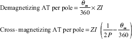
- Number of compensating winding:
The number of armature-turns immediately under one pole
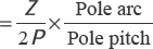
Approximately, the number of armature-turns immediately under one pole is given by

Therefore, the number of AT/pole for compensating winding is given by
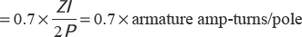
- Value of reactance voltage:
Reactance voltage or self-induced voltage
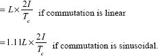
SHORT QUESTIONS AND ANSWERS
Ans. A DC generator is a rotating machine that converts mechanical energy into electrical energy and delivers DC.
Q.2 On what principle does the DC generator work?
Ans. The DC generator woks on the principle of Faraday's laws of electromagnetic induction.
Q.3 What are the differences between a DC generator and an alternator?
Ans. The differences between a DC generator and an alternator are shown below:
- In a DC generator field is static and armature is rotating, whereas in an alternator either field or armature can be made rotating, usually field.
- In DC generator generated alternating emf is rectified to DC by the arrangements of commutator. This kind of arrangement is not required in alternator.
- In DC generator a closed type of winding is arranged on the armature, but alternator coils are not arranged in closed fashion.
- A closed type of winding arrangement on armature is required in DC generator, whereas in the alternator coils are not arranged in closed fashion.
Q.4 What are the main parts of a DC generator?
Ans. The mains parts of DC generators are shown below: Stationary parts: (i) Yoke or body, (ii) Eye bolts, (iii) Pole shoes, (iv) Field winding, (v) Rocker ring, (vi) Carbon brushes, (vii) Brush holder and (viii) Side covers. Rotating parts: (i) Shaft, (ii) Armature core, (iii) Armature windings, (iv) Commutator, (v) Ventilating fan and (vi) Bearings.
Q.5 Mention the parts which form the magnetic circuit.
Ans. (i) Yoke, (ii) Pole cores, (iii) Armature core and (iv) Air gaps (between the poles and armature core).
Q.6 What percentage of flux per pole does the yoke carry?
Ans. The yoke carries about 50 per cent of total flux per pole.
Q.7 What do you mean by magnetic leakage and leakage co-efficient of a DC machine?
Ans. In a DC machine a portion of the total flux developed in the poles completes its path through the air without entering the armature core, and this is known as magnetic leakage. The ratio of the total flux developed in the poles to the total useful flux entering the armature core is called the leakage co-efficient of a DC machine. The value of leakage co-efficient lies between 1.1 and 1.2.
Q.8 How many types of pole shoes are used in DC generators?
Ans. (i) Solid core made out of either cast iron or cast steel.
(ii) Laminated core built of thin laminations of annealed steel revetted together under hydraulic pressure.
Q.9 Why is the pole shoe curved?
Ans. The pole shoes are curved to give uniform air gap around the armature core.
Q.10 What are the functions of pole shoes in a DC machine? Ans. Pole shoes have the following functions:
- These support the field coils.
- These reduce the reluctance of the magnetic path.
- These achieve uniform flux distribution in the air gap by spreading out the flux.
Q.11 What will be the effect of increasing the air gap?
Ans. Reluctance will be increased. Therefore, the machine will draw more current in case of a motor and the machine will give less output in case of a generator.
Q.12 What are the factors on which the actual flux distribution depends?
Ans. The actual flux distribution depends upon (i) size of air gap, (ii) shape of pole shoes and (iii) clearance between the tips of the adjacent pole shoes.
Q.13 What are the functions of the armature core?
Ans. The armature core houses the armature windings and provides a low reluctance path for the magnetic lines of force.
Q.14 Is the armature core made of solid homogeneous material?
Ans. No, it is made of laminations of silicon steel.
Q.15 Why is the armature core laminated?
Ans. Armature core is laminated to reduce eddy current losses.
Q.16 Why are holes provided in the armature core?
Ans. Holes are provided in the armature core to reduce the weight of the core as well as to provide air circulation for cooling the core.
Q.17 Why is the armature core not made of wood?
Ans. Armature core is not made of wood because of its high reluctance and incapability of bearing high rotational torque.
Q.18 State the uses of lap and wave windings?
Ans. Lap winding is used for low-voltage and high-current DC machines, whereas wave winding is used for low-current and high-voltage DC machines.
Q.19 What is commutator?
Ans. Commutator is a cylindrical structure attached to the armature and mounted on the same shaft, segments of which are separated from one another by mica insulation and connected to armature coils through risers.
Q.20 What is dummy coil and why is it used?
Ans. Dummy coils are inactive filler coils. These are placed in the excess slots not required by the armature winding. These are not connected to the rest of the winding and commutator segments, but are taped. Dummy coils are used in the armature to get mechanical balance of the armature.
Q.21 What are the different types of DC generators according to their field excitation?
Ans. There are two types:
- Separately excited generators
- Self-excited generators
Q.22 What do you mean by self-excited generator?
Ans. A generator in which the field coils are excited by the generator's armature current itself, is known as self-excited generator.
Q.23 How does a self-excited generator produce emf at starting?
Ans. At starting, some residual magnetism left with the pole induces some emf in the armature, which causes some current in the armature, a part or whole of which, passing through the field, further strengthens the field flux and gradually the voltage is built up.
Q.24 What are the types of self-excited generators?
Ans. (i) Series generator, (ii) Shunt generator and (iii) Compound generator.
Q.25 What do you mean by series generator?
Ans. A generator in which the field windings, consisting of a few turns, is connected in series with the armature, that is, same current will flow through the armature, the field and the load, is said to be a series generator.
Q.26 What will be the effect if the resistance of series field winding is high?
Ans. The voltage at the external load point will be less due to consumption of a major part of the generated voltage in the series field winding having high resistance.
Q.27 How is the shunt field winding wound?
Ans. Shunt field winding is wound with a large number of turns of thin wire having sufficient high resistance to bear the generated voltage as it is connected across the armature.
Q.28 What is the usual value of shunt field current?
Ans. The usual value of the shunt field current is about 2to5 per cent of the total full-load current.
Q.29 Give the expression of generated emf of a DC generator.
Ans.
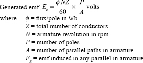
Q.30 What are the factors on which the emf of a DC generator depends?
Ans. The induced emf depends upon the following factors:
- The intensity of the magnetic field.
- The length of the armature conductors and the number of turns.
- The rate at which the armature conductors cut off the magnetic field or the speed of rotation in rpm.
Q.31 What are the losses in a DC machine?
Ans. There are three types of losses:
- Cu-losses →(Armature copper loss + Field copper loss)
- Iron losses →(Hysteresis loss + Eddy current loss)
- Mechanical losses → (Frictional + Windage)
Q.32 What is hysteresis loss?
Ans. The loss of energy in the form of heat, to overcome the molecular magnetic friction during reversal of magnetization of the armature core is called hysteresis loss. It depends upon the volume and grade of iron, maximum value of flux density and frequency of magnetic reversal.
Q.33 What is eddy current loss?
Ans. The loss of energy in the form of heat, which is caused by the flow of eddy current induced in the armature, pole and magnetic cores by the changing emf is called eddy current loss. The eddy current loss depends upon the range of the variation of flux density, the frequency of the variation of flux thickness of the iron lamination and the volume of the magnetic material. The loss varies directly as the square of the thickness of lamination.
Q.34 How is the eddy current in an armature core minimized?
Ans. Eddy current is minimized by laminating the armature core.
Q.35 What should be the place of lamination?
Ans. The armature core should be laminated at right angles to its axis.
Q.36 Why are eddy currents induced in the armature core of a DC machine?
Ans. Eddy currents are induced due to relative rotation between the field and the armature.
Q.37 What is the usual formula for calculating eddy current losses?
Ans. The eddy current loss We = KeBm2f2Vlt2
where K = Constant depending upon the electrical resistance of the magnetic material and the units employed in the expression,
Bm = Maximum flux density,
f = Frequency of magnetic cycles per second,
t = Thickness of the magnetic material and
Vl = Volume of the magnetic material.
Q.38 Does a change in speed affect iron losses and how?
Ans. Yes. hysterisis loss directly varies with the speed and eddy current loss varies with the square of the speed of the machine.
Q.39 What are stray losses?
Ans. Magnetic and mechanical losses are collectively known as stray losses. They are also known as rotational losses.
Q.40 What is the cause of mechanical losses in the armature?
Ans. The cause of mechanical losses in an armature is the speed of the armature.
Q.41 What is the relation between mechanical losses and speed of the armature?
Ans. Windage loss is proportional to the square of the speed of the armature, but frictional loss is proportional to the speed of the armature.
Q.42 Why is the output power of a DC generator always less than the input power?
Ans. Output power of a DC generator is always less than its input power because of the copper losses, iron and frictional losses and windage losses, which occur during running of the generator.
Q.43 What are the power stages in a DC generator?
Ans. Mechanical power input - Iron and frictional losses = Electrical power developed in armature (EI), Electrical power developed in armature - Copper losses = Electrical power output (VIII)
Q.44 What is the condition for maximum efficiency in a DC generator?
Ans. The efficiency is maximum when variable losses = constant losses.
Q.45 What is an equalizer ring?
Ans. An equalizer ring is a balancing ring made of copper conductors fitted at the driving end of the armature. It may also be a separate winding behind the commutator of a DC machine connected to two or more points of the armature windings to provide a low-resistance path at the same potential.
Q.46 Where are equalizer rings used in a DC generator and why?
Ans. Equalizer rings are used in lap winding and duplex, triplex wave winding of a DC machine to avoid unequal distribution of current at the brushes as well as to get sparkless commutation.
Q.47 What is the relation between the numbers of commutation segments and the number of armature coils in a DC machine?
Ans. In DC machines the number of commutator segments is equal to the number of armature coils.
Q.48 What is the function of a commutator?
Ans. Function of a commutator is to facilitate the collection of current from the armature conductors and to convert the alternating emf induced in the armature conductors into unidirectional emf in the external load circuit.
Q.49 What is the main purpose of using carbon brushes in a DC machine?
Ans. Carbon brushes are used to improve the commutation process.
Q.50 Where are copper brushes used in a DC machine instead of carbon brushes?
Ans. Copper brushes are used in a DC machine where high currents and low voltage are involved.
Q.51 What is the magnetic neutral axis (MNA)?
Ans. The MNA is defined as the axis which is at right angles to the main pole flux passing through the armature along which no emf is produced in the armature conductors. It is also known as the axis of commutation.
Q.52 What is geometrical neutral axis (GNA)?
Ans. The GNA is the axis, which bisects the angle between two adjacent poles.
Q.53 What is commutating plane?
Ans. It is the magnetic neutral plane (MNP).
Q.54 What is the position of collecting maximum emf?
Ans. Maximum emf is collected at magnetic neutral plane.
Q.55 Why are the brushes shifted from the geometrical neutral axis in a DC generator?
Ans. The brushes are shifted from the geometrical neutral axis in a DC generator to avoid sparking on the commutator.
Q.56 What is armature flux?
Ans. When the generator is loaded, the armature carries its load current that produces a magnetic flux around the armature, which is called the armature flux.
Q.57 What do you mean by back torque of a DC generator and what are its effects? Ans. Back torque of a DC generator means the torque developed in the armature due to load current in opposite direction to the direction of rotating of prime time mover. Back torque determines the power requirement of the prime mover due to which power of the prime mover is kept more than the maximum generator output.
Q.58 What is armature reaction?
Ans. The effect of magnetic field set up by armature current on the distribution of magnetic lines of force produced by the main field poles of a generator is called armature reaction.
Q.59 What is the function of compensating windings?
Ans. The function of compensating windings is to neutralize the cross-magnetizing effect of armature reaction, particularly in the zones outside the influence of the interpoles, and thus maintain a uniform flux distribution under the faces of the main poles.
Q.60 What are the factors that create difficulties in the process of commutation of a non-interpolar DC machine?
Ans. The cross magnetizing effect of armature reaction and the self-induced emf in the coil undergoing commutation known as the reactance voltage create difficulties in the process of commutation of a non-interpolar DC machine.
Q.61 What are inperpoles and how are they connected?
Ans. Interpoles or commutating poles are small narrow poles situated midway between the main poles and are connected in series with the armature.
Q.62 What is the polarity of interpoles relative to that of main poles in a DC machine?
Ans. The polarity of interpoles in case of generators is the same as that of the main poles further ahead in the direction of rotation, whereas in case of motors their polarity is the same as that of the main poles further behind in the direction of rotation of the machine.
Q.63 Why is the air gap of interpoles made larger than that of the main poles?
Ans. Since both the armature reaction and the emf of self-induction in the coils undergoing commutation are proportional to the armature current, the flux density necessary to compensate for them, produced by the interpoles, may also be proportional to the armature current to keep the interpole flux nearly proportional to the armature current at all loads, so the air gap between the interpoles and the armature is made larger.
Q.64 What is the difference between compensating winding and interpoles?
Ans. Although they are connected in series and their emf are such as to neutralize armature reaction, the interpoles additionally supply mmf to counteract the reactance voltage induced in the coil undergoing commutation.
Q.65 What are the important characteristics of a DC generator? Ans. The three important characteristics are:
- No-load saturation characteristic (E0/I)
- Internal or total characteristic, (E/I)
- External characteristic (V/I)
Q.66 What do you mean by no-load saturation characteristic?
Ans. It is the magnetic characteristic of open-circuit characteristic that gives the relation between the no-load generated emf in armature (E0) and the field or exciting current at a given fixed speed.
Q.67 What do you understand by external characteristic?
Ans. It is the performance characteristic that gives the relation between the terminal voltage (V) and the load current (Iz).
Q.68 What are the conditions for building up of a self-excited shunt generator?
Ans. The conditions are as follows:
- There must be some residual magnetism in the poles.
- The shunt field windings should be correctly connected to the armature for the given direction of rotation so that the induced current can reinforce the emf produced initially due to residual magnetism.
- If the generator is excited in open circuit, its shunt field resistance should be less than the critical resistance.
- If excited on load, its shunt field resistance should be more than a certain minimum value of resistance, which is given by internal characteristic.
Q.69 Can a shunt generator build up its voltage without residual magnetism?
Ans. A shunt generator cannot build up its voltage without residual magnetism.
Q.70 Can a DC generator be made to build up with reversed direction of rotation?
Ans. Yes, a DC generator can be made to build up in reverse direction of rotation.
Q.71 Why does the voltage of a shunt generator drop as load is applied to its terminals?
Ans. (i) The terminal voltage is less than the induced emf by the resistance drop in the armature.
(ii) Armature reaction weakens the field and so reduces the induced emf.
(in) The drop in terminal voltage due to resistance drop and armature reaction results in a decreased field current, which in turn reduces the induced emf.
Q.72 What types of generators would you like to install in (i) hotels and office and (ii) in power houses?
Ans.
- Hotels and office buildings - For short distances such as in hotels and office buildings level-compound generators are used because the voltage drop over small lengths of the feeder is negligible.
- Power houses - To supply power from the power houses, it is required to maintain constant voltage at the end of a long feeder. Hence, over-compound generators are best suited for this purpose.
Q.73 What will be the effect on the terminal voltage when the series field is short circuited at full load in case of (i) cumulative compound and (b) differential compound generator?
- Due to reduction in the resultant flux in the air gap the terminal voltage will be reduced.
- Due to the rise in the resultant flux in the air gap the terminal voltage will rise.
Q.74 What do you mean by parallel operation of DC generators?
Ans. Parallel operation of DC generators means running two or more DC generators in parallel on the same bus.
Q.75 What are the conditions to be fulfilled for parallel operation of two or more DC shunt generators?
Ans. The following three essential conditions should be ensured before paralleling DC shunt generators:
- The terminal voltage of the generators must be equal.
- The polarities must be same, that is, positive should be connected to positive and negative to negative.
- The generator characteristics must be similar in form, and each must have the same voltage drop from no load to full load.
Q.76 What are the conditions to be fulfilled before paralleling two DC compound generators?
Ans. The conditions are as follows:
- The terminal voltages must be same.
- The polarities must be same.
- The generator characteristics must be similar.
To maintain proper division of load from no load to full load, the following conditions must be satisfied in addition to the above conditions: - The regulation of each armature must be the same.
- The series field resistance must be inversely proportional to the generator ratings.
Q.77 What are the causes of overloading?
Ans. Overloading is caused by the following:
- Excessive voltage due to over excitation in field magnets on high speed of the prime mover.
- Excessive current due to bad feeding of load or short circuit in the generator itself or in the external load circuit.
- Reversal polarity.
SUPPLEMENTARY PROBLEMS
1. A 20 kW DC compound generator works on full load with a terminal voltage of 250 V. The armature, series and shunt windings have resistances of 0.05 Ω, 0.025 Ω and 100 Ω, respectively. Calculate the total emf generated in the armature when the machine is connected as short shunt.
[Ans. 256.126 V]
2. A DC shunt generator has an induced voltage on open circuit of 127 V. When the machine is on load, the terminal voltage is 120 V. Find the load current if the field circuit resistance is 15 Ω and armature resistance is 0.02 Ω. Ignore armature reaction.
[Ans. 342 A]
3. A six-pole lap-wound DC generator has 70 slots with 20 conductors per slot. The ratio of pole arc to pole pitch is 0.68. The diameter of the pole shoe is 0.46 m. The length of the pole shoe is 0.3 m. If the air gap flux density is 0.3 Wb/m2 and the emf induced in the armature is 400 V, find the speed at which it runs.
[Ans. 1,163 rpm]
4. A 110 V DC shunt generator has a full-load current of 100 A, shunt field resistance of 55 Ω and constant losses of 500 W. If full-load efficiency is 88 per cent, find the armature resistance. Find the load current corresponding to maximum efficiency.
[Ans. 0.078 Ω, 96.1 A]
5. A DC shunt generator has a full-load current of 196 A at 220 V. The stray losses are 720 W and the shunt field resistance is 55 Ω. It has full-load efficiency of 88 per cent. Find the armature resistance and the load current corresponding to maximum efficiency.
[Ans. 0.107 Ω, 122.3 A]
6. A 250 V, 500 kW, eight-pole DC generator has a lap-wound armature with 480 conductors. Calcu- late the demagnetizing and cross-magnetizing AT per pole at full load if brushes are given a forward lead of 7.5° (mechanical).
[Ans. 2,500 AT, 5,000 AT]
7. A four-pole wave-wound DC shunt generator runs at 1,000 rpm when supplying 330 lamps each rated at 60 W, 110 V. It has a shunt field current of 2 A. There are 90 commutator segments and brush width is equal to 1.1 commutator segments. The self-inductance of each coil is 0.025 mH. Determine the reactance voltage if the commutation is (i) linear and (ii) sinusoidal.
[Ans. 6.2 V, 6.89 V]
8. A separately excited DC generator gave the following data for open-circuit characteristic at 1,000 rpm.
![]()
The armature resistance including brushes is 0.5 Ω. If the generator is now shunt connected and is driven at 1,100 rpm, then for a total shunt field resistance of 180 Ω, calculate (i) no-load emf and (ii) the output current and shunt field current for a terminal voltage of 190 V (neglect armature reaction).
[Ans. (i) 221 V (ii) 43.94 A, 1.06 A]
9. Two DC shunt generators run in parallel together to supply 2,500 A. The machines have armature resistances of 0.04 Ω and 0.025 Ω, field resistances of 25 Ω and 20 Ω and induced emfs of 440 V and 420 V, respectively. Find the bus bar voltage and output of each machine.
[Ans. 388.7 V, 492.54 kW, 479.21 kW]
10. Two DC shunt generators and a battery are working in parallel. The open-circuit voltage, armature and field resistances of generators are 250 V, 0.02 Ω, 120 Ω and 248 V, 0.10 Ω and 120 Ω, respectively. If the generators supply the same current when the load on the bus basis is 50 A, calculate the emf of the battery if its internal resistance is 0.16 Ω.
[Ans. 248.2 V]
MULTIPLE-CHOICE ΩUESTIONS AND ANSWERS
1. The rotating part of a DC machine is
(a) armature (b) field (c) both (a) and (b) (d) none of these
2. The actual generated voltage in a DC generator is
(a) direct (b) alternating (c) partly (a) and (b) (d) none of these
3. DC machines are characterized by
(a) magnetic poles (b) armature (c) electric brushes (d) commutator
4. The function of a commutator in a DC machine is
(a) to provide easy speed control (b) to improve commutation
(c) to convert alternating voltage to direct voltage (d) to convert ac current to DC current
5. The laminated parts of a DC machine are armature and
(a) pole shoe (b) core (c) yoke (d) pole
6. Residual magnetism is necessary in a DC
(a) shunt motor (b) series motor
(c) separately excited generator (d) shunt generator
7. If a shunt generator delivers 100 A at 200 V and the resistance of the shunt field and armature are 100 Ω and 0.01 Ω, respectively, the generated emf will be
(a) 205 V (b) 212 V (c) 201.02 V (d) 208 V
8. The condition for maximum efficiency of a DC generator is
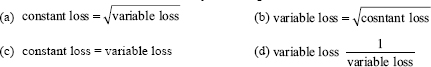
9. The main cause that delays or retards the quick reversal of current is
(a) the reactance voltage
(b) resistance of the brush being large
(c) the air gap between the brushes and the commutator segments
(d) none of these
10. If the armature current is increased to double its previous value and the time of commutation is halved, the reactance voltage will
(a) remain the same (b) be doubled (c) be halved (d) become four times
11. DC shunt generator has
(a) slightly drooping characteristic (b) constant voltage characteristic
(c) appreciably rising characteristic (d) appreciably drooping characteristic
12. The function of interpoles of a DC generator is to neutralize
(a) reactance voltage (b) current unbalance at the pole tip
(c) cross-magnetizing effect of armature reaction (d) none of these
13. For charging batteries, we use
(a) shunt generator (b) series generator
(c) compound generator (d) any of the above
14. In a DC generator, sparking at brushes results due to
(a) armature reaction (b) reactance voltage in coil undergoing commutation
(c) winding distribution (d) high constant resistance at the brushes
15. The copper losses of a DC shunt generator amount to the following percentage of full-load losses:
(a) 10 to 20% (b) 20 to 25% (c) 30 to 40% (d) none of these
16. Stray losses in a DC generator are the same as
(a) magnetic losses (b) mechanical losses
(c) either (a) or (b) (d) sum of (a) and (b)
17. Standing or constant losses of a DC shunt generator are
(a) stray losses (b) field losses of shunt generator
(c) armature losses of a compound (d) both (a) and (b)
18. The voltage of a DC generator may conveniently be increased by
(a) decreasing the air gap flux density (b) increasing the speed of rotation
(c) decreasing the speed of rotation (d) both (a) and (b)
19. If external resistance is added to the field of a DC shunt generator, it results in
(a) decrease in the voltage of the generator (b) increase in the power delivered
(c) increase in the voltage of the generator (d) increase in the speed of the generator
20. Hysteresis loss in a DC generator may be reduced by
(a) using material having small hysteresis loop (b) laminating the core material
(c) both (a) and (b) (d) none of these
21. During maximum efficiency, the load current of a DC generator is givenby
![]()
22. Overall efficiency of a DC generator is usually in the order of
(a) 70 to 75% (b) 75 to 85% (c) 80 to 90% (d) 85 to 95%
23. The armature current of a DC shunt generator is
![]()
24. For supplying power to short distances such as in office buildings, generators used are
(a) series generators (b) under-compounded generators (c) over-compounded generators (d) flat-compounded generators
25. In DC generators, the effect of armature emf on the main pole flux distribution is to
(a) produce no distribution
(b) distort it
(c) shift the zero crossing of resultant flux density wave in the direction of rotation
(d) shift the zero crossing of resultant flux density wave against the direction of rotation
26. A four-pole DC generator is running at 1,500 rpm. The frequency of current in the armature winding is
(a) 25 Hz (b) 35 Hz (c) 50 Hz (d) 60 Hz
27. The internal characteristic of a generator is plotted between the
(a) field current and voltage generated at no load
(b) armature current and voltage generated after armature reaction
(c) field current and voltage generated on load
(d) armature current and voltage actually generated at the output terminals
28. Level-compounded DC generator is used for the following application.
(a) Electric arc welding (b) Battery charging
(c) Electric traction (d) Lighting
29. Hysteresis loss in electric machines is reduced by (1) and eddy current loss by (2)
(a) (1) less flux, (2) less current
(b) (1) special steel (2) thin insulated lamination
(c) (1) more poles (2) increased speed
(d) (1) and (2) by increased winding in rotor and stator
30. Hysteresis and eddy current losses in electric machines depend on
(a) flux density (b) speed (c) speed and flux density (d) voltage only
31. Among the three losses - electrical, magnetic and mechanical -
(a) mechanical loss is minimum
(b) all the three losses are equal
(c) magnetic losses are highest Terminal voltage
(d) mechanical loss is the minimum at about 15 per cent of total losses
32. The characteristics of a compound DC generator are shown in Figure 1. Identify the curves.
(a) (I) Series (II) Dropping (III) Parabolic
(b) (I) Under compounding (II) Over compounding (III) Level compounding
(c) (I) Over compounding (II) Level compounding (III) Under compounding
(d) (I) Shunt (II) Series (III) Series-parallel
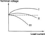
33. In a series generator the field resistance is 650 Ω and the load resistance is 800 Ω.
(a) The machine will not excite
(b) The machine will deliver a low voltage
(c) The machine will deliver a high voltage
(d) None of these
34. The chief difference in the external characteristics of a series and shunt DC generator is that
(a) it becomes unstable beyond a certain load current
(b) it has dropping characteristics
(c) it has two critical resistances
(d) there is no difference
35. In the series field generator, the resistance should be (i) while for the shunt field generator it should
be (ii)
(a) (i) high (ii) low (b) (i) low (ii) high (c) (i) and (ii) same (d) immaterial
36. In the armature conductors of a DC generator
(a) maximum emf is produced (b) maximum current is produced
(c) minimum current is produced (d) minimum emf is produced
37. If P be the number of poles of a DC generator, cross magnetizing AT per pole is equal to
![]()
38. The number of AT per pole for compensating winding of a DC generator is given by
![]()
39. To get a constant voltage output at all loads, we use
(a) series generator (b) shunt generator
(c) level-compound generator (d) short-shunt compound generator
40. In the commutation process
(a) current reverses (b) voltage reverses
(c) both (a) and (b) (d) partly (a) and (b)
41. The main reason for delay in reversal of current in a DC generator is
(a) the air gap between the brushes and the commutator surface
(b) reactance voltage
(c) both (a) and (b)
(d) none of these
42. To improve commutation, the following point (s) is (are) valid
(a) reduce the number of turns in armature and segments of commutator
(b) increase the resistance of brushes
(c) neutralize the reactance voltage by producing a reverse emf in the coil undergoing commutation
(d) all of these
43. The regulation of an ideal DC generator is
(a) 20% (b) 15% (c) 25% (d) none of these
44. Choose the correct statement.
(a) DC series generator is more popular than the shunt generator
(b) DC shunt generator is more popular than the series generator
(c) DC compound generator is the most popular
(d) All of these
45. The terminal voltage of DC shunt generator drops due to
(a) armature resistance (b) armature reactance
(c) weakening of field due to (b) (d) all of these
46. The critical resistance of a DC generator can be increased by
(a) increasing its armature resistance (b) increasing its speed
(c) increasing its field current (d) all of these
47. The function of an equalizer ring in a DC generator is
(a) to avoid unequal distribution of current at the brushes
(b) to get sparkless commutation
(c) partly (a) and (b)
(d) both (a) and (b)
48. The function of interpole or compole of a DC generator is
(a) to neutralize the demagnetizing effect of armature reaction
(b) to neutralize the reactance voltage and help in commutation process
(c) to neutralize the cross-magnetizing effect of armature reaction
(d) all of these
49. Equalizer ring is used in
(a) wave-wound armatures only (b) lap-wound armatures only (c) both (a) and (b)
50. The main reason for voltage not building up in a DC series generator is
(a) reversed terminal of field winding (b) short-circuited terminal
(c) disconnected load (d) reversed terminal of armature winding
51. For shifting load from one shunt generator to the other running in parallel, the simple method is
(a) adding resistance in their armature circuit (b) adjusting their field rheostat
(c) using equalizer connection (d) none of these
52. The maximum generated voltage of a DC generator is 650 V; the limitation is due to
(a) starter (b) commutator (c) field winding (d) armature winding
53. The function of equalizing connections of a lap-wound DC generator is
(a) to avoid unequal distribution of currents at brushes
(b) to avoid short-circuit current
(c) to neutralize the armature reaction
(d) all of these
54. For a specified open-circuit voltage of a DC generator, the short-circuit current will be maximum when it is
(a) separately excited (b) shunt connected
(c) commutatively over compounded (d) differentially compounded
55. In DC generators the polarities of the interpole is
(a) same as that of the main poles behind (b) same as that of the main pole ahead
(c) opposite to that of the main pole ahead (d) none of these
56. For building up voltage, residual magnetism is essential in field systems of all types of DC generator except
(a) series (b) shunt (c) compound (d) separately excited
57. The terminal voltage of a DC series generator running at rated speed and at no load is eΩual to (a) rated voltage (b) half of its rated voltage (c) zero (d) very little voltage
58. For parallel operation, the polarities of two generators
(a) must be the same (b) must oppose each other
(c) may or may not be the same (d) none of these
59. Generators are quite often run is parallel because of
(a) greater reliability (b) greater efficiency
(c) capability to meet greater demand (d) all of these
60. Find the type of generator that most suits parallel operation.
(a) Shunt generator (b) Series generator
(c) Compound generator (d) All of these
61. The critical resistance of a DC generator is the resistance of the field winding of the generator
(a) at which it can supply maximum power
(b) beyond which it just does not develop any voltage
(c) at which it develops maximum voltage
(d) all of these
62. The number of conductors for a wave-wound armature of a four-pole dynamo, having a flux of 106 lines and generating a voltage of 240 V when driven at 800 rpm is
(a) 900 (b) 400 (c) 200 (d) 300
Answers
| 1 (a) | 2 (b) | 3 (d) | 4 (c) | 5 (a) | 6 (d) |
| 7 (c) | 8 (c) | 9 (a) | 10 (d) | 11 (a) | 12 (a),(c) |
| 13 (a) | 14 (b) | 15 (c) | 16 (d) | 17 (d) | 18 (b) |
| 19 (a) | 20 (a) | 21 (c) | 22 (d) | 23 (d) | 24 (d) |
| 25 (c) | 26 (c) | 27 (b) | 28 (b),(d) | 29 (b) | 30 (c) |
| 31 (a) | 32 (c) | 33 (a) | 34 (c) | 35 (b) | 36 (d) |
| 37 (b) | 38 (a) | 39 (c) | 40 (a) | 41 (b) | 42 (d) |
| 43 (d) | 44 (b) | 45 (d) | 46 (b) | 47 (d) | 48 (c) |
| 49 (b) | 50 (b) | 51 (b) | 52 (b) | 53 (a) | 54 (a) |
| 55 (b) | 56 (d) | 57 (c) | 58 (a) | 59 (d) | 60 (a) |
| 61 (a) | 62 (a) |