9 Single-phase Motors and Special Machines
Single-phase supply is mainly used for lighting purposes in offices, shops, schools, houses. Besides lighting purposes, it has tremendous uses in our day-to-day life. Domestic applications include mixers, automatic washing machines, electric iron, hair dryers and others. The power rating of these types of machines is very small. These motors are also called fractional kilowatt motors because some of them have rating less than a kilowatt. The aim of this chapter is to introduce the construction, working principle and applications of these motors.
9.1 CLASSIFICATION OF SINGLE-PHASE INDUCTION MOTORS
Fractional kilowatt motors have the following classifications:
- (i) Single-phase induction motors:
(a)Resistance split type, (b) capacitor split type and (c) shaded pole type - (ii) Single-phase synchronous motors:
(a)Reluctance motors and (b) hysteresis motors - (iii) Single-phase induction motors:
(a)AC series motors and (b) universal motors - (iv) Special purpose motors:
(a)Stepper motors and (b) servomotors
9.2 PRODUCTION OF ROTATING FIELD
Figure 9.1 shows two windings A and B. These windings are displaced in such a way that the magnetic fields produced in space are 90° apart. Let the magnetic field produced by the two windings be equal in magnitude and 90° apart in time. These are represented by:
![]()
These two magnetic fields produce a resultant magnetic field having a constant magnitude Φm, which is rotating, as shown in Figure 9.2.
If the windingsnn A and B are displaced in space by 90° and produce fields such that they are not equal in magnitude and not 90° apart in time, the resultant magnetic field is a rotating magnetic field having variable magnitude throughout the revolution. The non-uniform magnetic field produces a non-uniform torque causing the operation to be noisy. A motor producing non-uniform rotating field has less starting torque compared with that of a motor of the same rating producing a uniform rotating field.
.jpg)
.jpg)
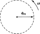
Figure 9.2 Resultant Magnetic Field
9.3 WORKING PRINCIPLE OF SINGLE-PHASE INDUCTION MOTOR
For operation as a motor, there must be two fluxes that will interact with each other and produce the torque. The field winding in DC motor produces the main flux. The DC supply is given to the armature and armature flux is produced. The electromagnetic torque is produced due to the interaction of the above two fluxes. However, in single-phase induction motors, no DC supply is applied to the rotor and single-phase AC supply is applied to the stator only. Therefore, stator produces alternating flux which is known as main flux. This flux links with the rotor conductors and emf is induced in it due to transformer action. Since the rotor is a closed circuit, this emf drives the current through it resulting in rotor flux. Since the second flux is produced according to induction principle due to induced emf, the motor is termed as induction motor. The main differences of DC and AC motors are:
- No separate DC supply is required to rotor in single-phase induction motor, whereas separate DC supply is required to armature in a DC motor.
- DC motors are self-starting, whereas single-phase induction motors are not self-starting.
With the help of double revolving field theory and cross-magnetic field theory, we can explain why single-phase induction motors are not self-starting.
9.4 DOUBLE REVOLVING FIELD THEORY
The pulsating magnetic fields produced by the single-phase induction motors can be resolved into two rotating magnetic fields with the help of double revolving magnetic field theory. All the magnetic fields have equal magnitude and they rotate in opposite directions. The resultant torque is the sum of the two torques.
The equation of alternating magnetic field having axis fixed in space is represented by
where αmax is the amplitude of the sinusoidally distributed air gap flux.
.jpg)
.jpg)
.jpg)
.jpg)
.jpg)
Figure 9.3 Forward and BackwardFields
Equation (9.1) can be written as:
Equation (9.2) has two terms. The first term and second term represent the revolving field moving in the negative and positive direction, respectively, having amplitude equal to 1/2 αmax. The fields in the positive and negative a direction are called forward and backward rotating fields both rotating at a synchronous speed ωs (2π ns).
Therefore, the pulsating magnetic field is resolved into forward and backward rotating magnetic fields having equal magnitude and rotating at synchronous speed. Therefore, the rotor is stationary.
The above facts are represented by Figure 9.3.
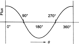
In Figure 9.3(a), both fluxes A and B are in phase with the reference. Therefore, the net flux is maximum. In Figure 9.3(b), both fluxes are at an angle θ with the reference. In Figure 9.3(c), both fluxes are at an angle of 180°. Hence, the resultant flux is zero. In Figure 9.3(d), both fluxes are at an angle of 0° but in the direction opposite to Figure 9.3(a). Hence, resultant flux is once again maximum but in the opposite direction of Figure 9.3(a). In Figure 9.3(e), both fluxes are at an angle of 180° but the position of fluxes A and B are opposite to Figure 9.3(a). Figure 9.4 represents the resultant flux.
Therefore, we can conclude that the single-phase induction motor with single stator winding cannot produce self-starting torque. Although the rotor is stationary, let us give it an initial rotation in either direction. The torque due to rotating magnetic field in the initial direction will be greater than the torque due to rotating magnetic field in the other direction. Therefore, a net positive torque is produced in the direction of initial rotation, and hence the motor will continue to run in the same direction of initial rotation.
9.5 ROTOR SLIP WITH RESPECT TO TWO ROTATING FIELDS
After starting the induction motor by means of auxiliary means, a resultant torque is produced and it will keep running in the same direction of one of the fields. The direction in which the rotor is started initially is known as forward field by definition.
The slip (sf) of the rotor with respect to the forward rotating field is given by
![]()
where ns and n are the synchronous speed and rotor speed, respectively.
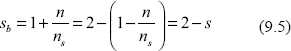
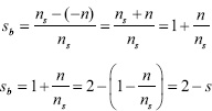
The slip (sb) of the rotor with respect to the backward rotating field is given by
From Equation (9.4), we have:
.jpg)
.jpg)
Figure 9.5 Rotor Equivalent Circuit
In single-phase induction motor, the speed of the rotor is less than the synchronous speed. Equations (9.3) and (9.5) represent the motor (a operation and the braking region. Figures 9.5(a) and 9.5(b) shows the rotor equivalent circuits corresponding to the forward and backward rotating fluxes, respectively.
Figure 9.6 shows the torque-speed characteristics of single-phase induction motor.
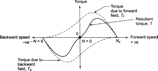
Figure 9.6 Torque-speed Characteristics of Single-phase Induction Motor
9.6 EQUIVALENT CIRCUIT OF SINGLE-PHASE, SINGLE-WINDING INDUCTION MOTOR
Auxiliary windings are connected to induction motors to make them self-starting. Therefore, single-phase induction motors, in fact, are two-phase motors. Figure 9.7 shows the equivalent circuit of a single-phase induction motor having stationary rotor. In Figure 9.7, core loss branch has not been shown because core loss branch is assumed to be lumped with the mechanical and stray losses as a part of rotational losses of the motor.
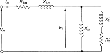
Figure 9.7 Equivalent Circuit of Single-phase Induction Motor at Standstill
In Figure 9.7
Rlm: Resistance of main rotor winding
Xlm: Leakage reactance of the main stator winding
XM: Magnetising reactance
R'2: Standstill rotor resistance to main stator winding
X'2: Standstill rotor leakage reactance to main stator winding
V: Applied voltage
Im: Main winding current
Since the pulsating magnetic field is resolved into backward and forward fields having equal and opposite fluxes with the motor, the magnitude of each rotating flux is one–half of the alternating flux. Therefore, it is assumed that the two rotating fluxes are acting on two separate rotors. Hence, we can assume that the single–phase induction motor consists of two rotors having a common stator winding and two imaginary rotors. At standstill, the impedance of each rotor referred to stator winding is 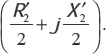 Figure 9.8 shows the equivalent circuit of single–phase induction motor at standstill with the effect of separating forward and backward rotating fluxes.
The emfs induced in the main stator winding by the forward and backward fluxes are Emf and Emb', respectively. The resultant-induced emf (Em) in the stator winding is given by
![]()
Since the circuits of rotors due to the forward and backward fields are identical at standstill, we have
![]()
If the motor is started with the help of auxiliary windings and the auxiliary windings are switched out after reaching certain speed, the effective rotor resistance depends on the slip. Let s be the slip due to the forward field. The effective rotor resistances due to forward and backward fields are ![]() and
and  respectively. The equivalent circuit is shown in Figure 9.9, taking into account forward and backward fields.

Figure 9.8 Effect of Separating Forward and Backward Rotating Fluxes at Standstill
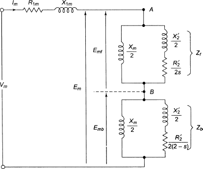
Figure 9.9 Equivalent Circuit Due to Forward and Backward Fields During Running
The rotor impedance due to the forward field is 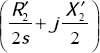 and it is in parallel with
 ![]() . Again, the rotor impedance due to the backward field is
. Again, the rotor impedance due to the backward field is 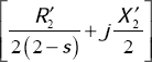 and it is in parallel with
 ![]() .
.
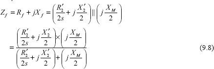
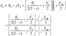
Now, equivalent impedance (Zf) of imaginary rotor due to forward rotating field is
and the equivalent impedance (Zb) of imaginary rotor due to backward rotating field is
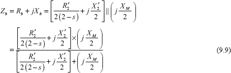
Figure 9.10 shows the simplified circuit.
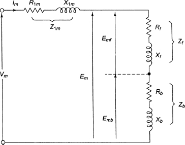
Figure 9.10 Simplified Circuit
From Figure 9.10, the current in stator winding is given by
![]()
9.7 POWER DEVELOPED AND LOSSES OF SINGLE-PHASE, SINGLE-WINDING INDUCTION MOTOR
To calculate the losses as well as the power of single-phase, single-winding induction motor, let us con-sider Figure 9.10. The torque due to backward field opposes the torque due to forward field. The total air gap power of single-phase induction motor is given by
![]()
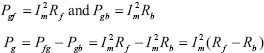
where Pgf and Pgb are the air gap power due to forward and backward fields, respectively.

The torque due to forward field is given by
![]()
Again, the torque due to backward field is given by
![]()
where ωs represents the synchronous speed.
The resultant torque is given by
![]()
The Cu loss of the single-phase motor is given by
![]()
where Prf and Prb are the Cu loss of the rotor due to forward and backward fields, respectively. The mechanical power developed in induction motor is given by
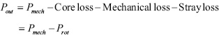
![]()
Shaft output power is given by
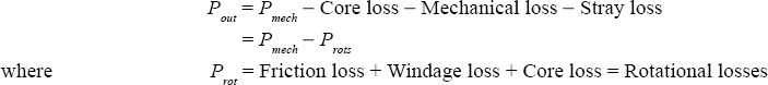
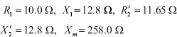
Example 9.1 The equivalent circuit parameters of a 230 V, 50 Hz, single-phase induction motor having friction, windage loss and core loss of 50 W are given below:
![]()
Calculate (i)input current, (ii)power factor, (iii)developed power, (iv)output power and (v)efficiency for a slip of 0.04.
Solution
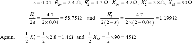
For forward field,
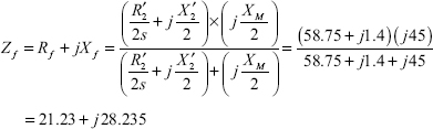
and the equivalent impedance (Zb) of imaginary rotor due to backward rotating field is

- Input current
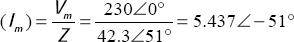
- Power factor = cos(-51°) = 0.629[lagging]
- Developed power =

- Output power = 580.76 - 50 = 530.76 W
- Input power =

![]()
9.8 DETERMINATION OF EQUIVALENT CIRCUIT PARAMETERS
To determine the parameters of the equivalent circuit of induction motor, the blocked rotor test and no-load test are carried out. These tests are similar to the tests for induction motor except for capacitor start motor because in capacitor start motor, these tests are conducted with auxiliary circuit open.
9.8.1 Blocked Rotor Test
During this test, rotor is kept blocked and a low voltage supply is given to the stator to maintain the rated current in main winding. The voltage (Vx), current (Ix) and power (Px) are measured. During the blocked rotor test, s = 1 and can be neglected compared with ![]() . Figure 9.11 shows the equivalent circuit of the single-phase induction motor during blocked rotor test.
. Figure 9.11 shows the equivalent circuit of the single-phase induction motor during blocked rotor test.
From Figure 9.11, the equivalent series resistance (R0) of the motor is given by
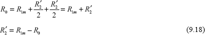
The effective rotor resistance at the line frequency can be calculated because R1m is already measured.
The equivalent series reactance (X0) of the motor is given by
![]()
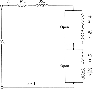
Figure 9.11 Equivalent Circuit of the Single-phase Induction Motor During Blocked Rotor Test
As we cannot separate Xlm and X'2, let us make the following simplified assumption:
![]()
Therefore, the parameters R2, X1m and X'2 can be calculated from blocked rotor test.
9.8.2 No-load Test
In this test, motor is run without load at rated voltage and frequency. The rated voltage is applied and the voltage (V0), current (I0) and power (P0) are measured. During no-load test s ![]() 0 and hence
0 and hence ![]() is large compared with
is large compared with ![]() . Figure 9.12 shows the equivalent circuit of the induction motor. From Figure 9.12, the equivalent reactance at no-load is given by
. Figure 9.12 shows the equivalent circuit of the induction motor. From Figure 9.12, the equivalent reactance at no-load is given by
![]()
XM can be calculated because X1m and X'2 have already been calculated from blocked rotor test. The no-load power factor is given by
![]()
The no-load equivalent impedance is given by
![]()
and the no-load equivalent reactance is given by
![]()
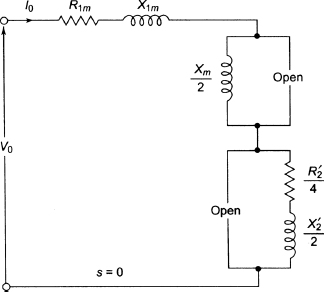
Figure 9.12 Equivalent Circuit of Induction Motor
Example 9.2 The test results of a 230 V, single-phase induction motor are given below:
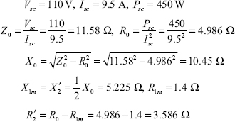
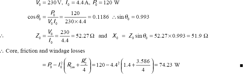
Blocked rotor test: 110 V, 9.5 A, 450 W
No-load test: 230 V, 4.4 A, 120 W
The starting winding is kept open during blocked rotor test and stator winding resistance is 1.4 Q. Find the equivalent circuit parameters and the core, friction and windage losses.
Solution
Blocked rotor test:
No-load test:
9.9 SPLIT-PHASE INDUCTION MOTORS
Figure 9.13 shows a split-phase induction motor which has a cage rotor and two stator windings (main winding and auxiliary winding). The main winding has very low resistance and high reactance, whereas the auxiliary winding has very high resistance and low reactance. The impedance of the auxiliary winding is very highly resistive in nature. The main winding is reactive in nature. The current (Im) through the main winding lags behind the voltage by an angle θm, whereas the current through the starting winding (Ist) is almost in phase with the voltage, as shown in Figure 9.14. Therefore, a time phase difference between Im and Ist exists which is of the order of 30° and not 90°. This phase difference is sufficient to produce a rotating magnetic field. The rotating magnetic is not uniform because the currents in the two windings are not the same. The starting torque is small and it is of the order of 1.5 to 2 times the rated running torque. During starting, both the windings are connected in parallel and supply is given. When the speed of the motor is about 70 to 80 per cent of synchronous speed, the starting winding is automatically disconnected from the supply. That is why auxiliary winding is also called starting winding. A centrifugal switch is used to disconnect the starting winding for motors having rating about 100 W or more. For smaller motors, a relay is connected in series with the main winding. During starting a heavy current flows through the coil which makes its contacts close and the starting winding is brought in circuit. When the motor achieves 70 to 80 per cent of synchronous speed, the current through the relay decreases and the relay opens resulting in disconnection of auxiliary windings from the supply. Now the motor runs on the main winding. Figure 9.15 shows the torque–speed characteristic of split–phase induction motor.
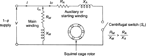
Figure 9.13 Split-phaseInductionMotor
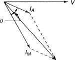
Figure 9.14 Phasor Diagram
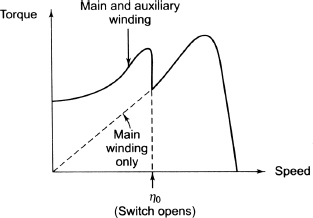
Figure 9.15 Torque-speed Characteristic of
Split-phase Induction Motor
The starting torque and the maximum or pull-out torque of this type of motors are of the order of 1.5 to 2.5 times of the full-load torque at about 75 per cent of synchronous speed. The staring current of the split-phase motors is generally 7 to 8 times of full-load current. To get the reversal of rotation, the motor at first is brought to rest and the line connections of either the main or auxiliary windings are reversed.
9.10 CAPACITOR MOTORS
A capacitor is used in series of auxiliary windings of single-phase induction motor so that the phase difference between the currents in main and auxiliary windings gets an appreciable value. The three different types of capacitors are discussed as follows.
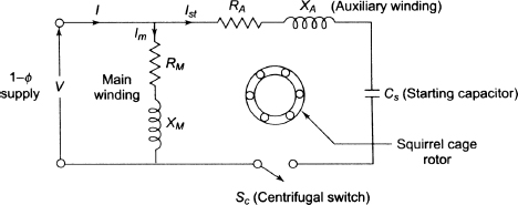
Figure 9.16 Capacitor-start Motor
9.10.1 Capacitor-start Motors
A capacitor-start motor is shown in Figure 9.16 having cage rotor and two stator windings – main winding and auxiliary winding. A properly selected capacitor (Cs) is connected in series with the auxiliary winding so that the current through the main winding (Im) lags behind the current of auxiliary winding (Ist) by an angle of 90°, as shown in Figure 9.17 and hence the motor acts like a balanced two-phase motor.
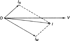
Figure 9.17 Phasor Diagram
As soon as the motor reaches 70 to 80 per cent of synchronous speed, the auxiliary winding, as well as the starting capacitor (Cs), is disconnected from the supply automatically by the centrifugal switch (Sc) which is mounted on the shaft. Therefore, the capacitor (Cs) is used only for starting purposes. The starting torque developed by the capacitor–start motor is higher than the split–phase induction motor which is of the order of 3 to 4.5 times of the full–load torque. To obtain the high starting torque, the value of starting capacitor must be large. The starting capacitor is of electrolytic type and is of the order of 250 μF Figure 9.18 shows the torque–speed characteristic of capacitor–start motor. To get reversal of rotation, the motor must be brought to rest at first and the line connection must be interchanged. This type of motor is suitable for loads of high inertia and hence is suitable for compressors, pumps, refrigerators, conveyors and others.
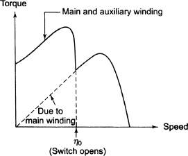
Figure 9.18 Torque-speed Characteristic
of Capacitor-start Motor
9.10.2 Capacitor-start Capacitor-run Motors
Figure 9.19(a) shows the capacitor-start capacitor-run induction motor having cage rotor and two stator windings – main winding and auxiliary windings. The motor has two capacitors Cs and Cr and these are connected in parallel at starting. The angle between the currents through the main winding and auxiliary winding is 90°. The value of Cs should be large to get high starting torque. It is short time rated and electrolytic in nature. Since the rated line current is smaller than the normal current during normal operation, the value Cr must be small. The capacitor stays in the circuit permanently and it has oil-filled paper con-struction. The capacitor is disconnected from the supply as the motor achieves 70 to 80 per cent of synchronous speed. This type of motor is quiet and smooth running and has higher efficiency compared with the motors running only on main windings. Figure 9.19(b) shows the phasor diagrams of capacitor-start capacitor-run induction motor.
.jpg)
.jpg)
Figure 9.19 (a) Capacitor-start Capacitor-run Motor (b) Its Phasor Diagram
Figure 9.20 shows the torque-speed characteristic of capacitor-start capacitor-run induction motor.
These motors are used for refrigeration, compressors and pumping equipment.
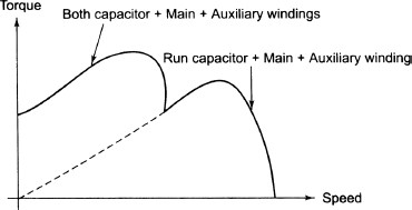
Figure 9.20 Torque-speed Characteristics of Capacitor-start Capacitor-run
Induction Motor
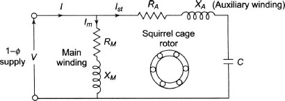
Figure 9.21 Permanent Split Capacitor Induction Motor
9.11 PERMANENT SPLIT CAPACITOR MOTORS
Figure 9.21 shows the permanent split capacitor induction motor having cage rotor and two stator windings - main winding and auxiliary windings. This type of motor has one capacitor (C) connected in series with the auxiliary windings permanently, and hence this type of motor is called single value capacitor motor. This type of motor has no starting switch and operates in the same way as capacitor-start capacitor-run induction motor. It produces a uniform torque and is less noisy during operation.
This type of motor is used for air conditioners to drive refrigerator compressors and fans and blowers of heaters. This type of motor has the following advantages:
- Higher efficiency
- Higher pull-out torque
- Higher power factor
- No centrifugal switch
The main limitations are:
- Low starting torque
- For continuous running, electrolytic capacitor cannot be used and paper capacitor of equivalent rating has larger size and costs more.
9.12 SHADED POLE MOTOR
The effect of shaded coil is to retard a portion of flux in the poles in time phase, so that there is a sweeping of the flux across the pole face in the direction of the shading of the coil, as shown in Figure 9.22.
.jpg)
.jpg)
Figure 9.22 Arrangement of Shaded Poles
The fluxes in the unshaded part of the pole and in the shaded part of the pole cut the rotor conductors and induce currents, which in turn produce a torque sufficient to start the motor. The shaded pole produces a weak starting torque and is used with fractional horse power motors, such as fan motors and shaving motors. Figure 9.23 shows the torque-speed characteristics of a shaded pole motor.
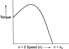
Figure 9.23 Torque-speed Characteristics
of a Shaded Pole Motor
This type of motor is cheap, having low starting torque, low power factor and low efficiency. This type of motor is used for small fans, advertising displays, toy motors, film projectors, record players, hair dryers, photocopying machines, and so on.
9.13 SINGLE-PHASE SYNCHRONOUS MOTORS
We know that synchronous motors have constant speed characteristic. Small-capacity synchronous motors are smaller in size and do not require DC excitation to rotor. There are two types of single-phase synchronous motors, namely, reluctance motors and hysteresis motors.
9.13.1 Reluctance Motors
Figure 9.24 shows a reluctance motor which is similar to a single-phase induction motor. The stator has both the windings - main winding and auxiliary windings. This type of motors has variable air gap and no DC supply is required to rotor. Salient-pole type of structure is given to the rotor, and it carries short-circuited copper bars acting like a squirrel cage rotor of induction motor. The starting torque is produced by any of the phase splitting methods. Air gap decides the reluctance of the magnetic path. Hence, more the air gap, Figure 9.24 Reluctance Motor more is the reluctance and less the air gap, less is the reluctance. The reluctance is greatest when the magnetic field of the stator magnetic field aligns with the cut out portion of the rotor, whereas it is least when it aligns with the centre portion of the rotor teeth. Therefore, the reluctance of the magnetic circuit is a function of the rotor position with respect to the axis of the stator field, that is, a function of the air gap. The rotor starts to rotate like a normal induction motor after giving the supply. The starting torque of this type of motor is very high and is solely dependent on the position of the rotor. Figure 9.25 shows the torque-speed characteristic of reluctance motor.
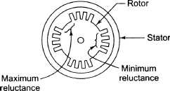
Figure 9.24 Reluctance Motor
This type of motor is used in control apparatus, automatic regulators, clocks and all kinds of timing devices, recording instruments, teleprinters and gramophones.
This type of motor has the following advantages:
- Less maintenance
- No requirement of DC supply
- Robust construction
- Constant speed characteristic
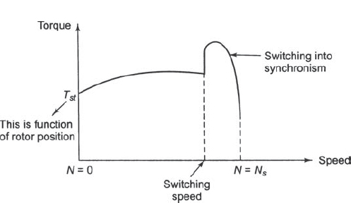
Figure 9.25 Torque-speed Characteristic of Reluctance Motor
This type of motor has the following limitations:
- Less efficiency
- Poor power factor
- Less capacity to drive loads compared with 3-phase synchronous motors
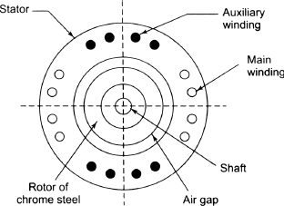
Figure 9.26 Hysteresis Motor
(Cross-section View)
9.13.2 Hysteresis Motor
Hysteresis motor is a synchronous motor having non-projected poles which does not need any DC excitation to rotor, as shown in Figure 9.26. The stator carries the main winding and auxiliary windings to produce the rotating magnetic field. The stator can also be of shaded pole type. The rotor is made of hard magnetic material such as chrome steel or alnico for high retentiv-ity and is of smooth cylindrical structure. The rotor has no winding and the material of the rotor must have high hysteresis loop area, as shown in Figure 9.27.
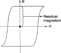
Figure 9.27 Hysteresis Loop for Rotor Material
After giving supply to the stator, the rotating magnetic field is produced that induces poles in the rotor. Since hysteresis phenomena is dominant in rotor material, rotor pole axis lags behind the rotating magnetic field. Therefore, the rotor poles get attracted towards the moving stator field poles and hence rotor gets subjected to torque known as hysteresis torque which is constant at all speeds. The rotor pole strength remains constant when the stator field axis moves forward. Therefore, higher is the hysteresis torque if higher is the retentivity. At the beginning, the rotor starts rotating due to the combined effect of hysteresis torque and torque due to eddy current induced in the rotor. The rotor pulls into synchronism when the speed of the rotor is near the synchronous speed. Magnetic locking between the rotor and stator is ensured by high retentivity. The motor either rotates at synchronous speed or not at all due to the principle of magnetic locking. The starting torque and running torque are almost equal in this motor.
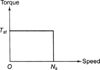
Figure 9.28 Torque-speed Characteristic of Hysteresis Motor
Figure 9.28 shows the torque-speed characteristic of hysteresis motor.
This type of motor has the following advantages:
- There are no mechanical vibrations because the rotor has no teeth and no winding.
- It can accelerate the high inertia load.
- There is possibility of multi-speed operation using gear train.
- The operation is quiet and noiseless due to absence of vibrations.
This type of motor is used for sound-recording instruments, sound-producing equipments, tape recorder, high-quality record players, teleprinters, timing devices and so on, because this type of motor has noiseless operation.
9.14 SERIES MOTOR OR UNIVERSAL MOTOR
A series motor can be run from either DC or AC (single-phase) supply, as shown in Figure 9.29 provided both stator and rotor cores are laminated to limit iron loss.
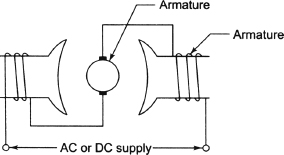
Figure 9.29 Universal Motors
Since both field flux and armature current change their magnitude and sign simultaneously, their product is always positive, even if both parameters individually are negative. Therefore, the torque produced by series motor is in the same direction for each half cycle of AC and is pulsating. We know:
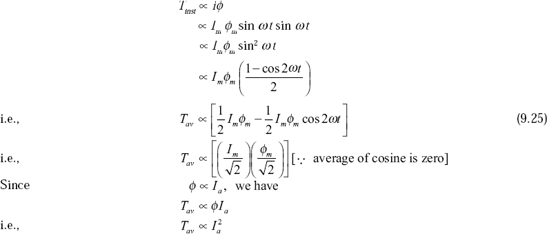
From Equation (9.25), it is seen that the instantaneous torque has an alternating compo-nent, whose frequency is double that of supply frequency. Figure 9.30 shows the field polarity is alternating with armature current variation.
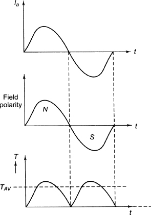
Figure 9.30 The Field Polarity Alternating
with Armature Current Variation
9.14.1 Circuit Model and Phasor Diagram
The net emf induced in the armature is the sum of the transformer emf and that due to leakage inductance (xa) and is given by
![]()
Since Et is caused by cross-flux whose origin is an armature current, the two must be in phase.
![]()
The net inductive emf in the armature circuit is
![]()
The circuit model of the AC series motor is shown in Figure 9.31.
9.14.2 Torque
As stated earlier, the torque developed is pulsating in nature with an average value and a predominant second harmonic component. The average torque is given by
![]()
Being a series motor, Eb ∝ Ia and the torque is therefore proportional to square of armature current, which becomes directly proportional at high armature current, because of saturation.
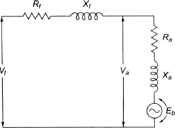
Figure 9.31 Circuit Model of AC Series Motor for AC Operation
9.14.3 Phasor Diagram and Performance Characteristics
In AC series motor, there will be a series drop in armature and field, along with reactance drop due to both in addition to rotational emf. Vector diagram of AC series motor is shown in Figure 9.32.
Ra, Rf = resistances of armature and field winding, respectively
Xa, Xf = reactances of armature and field winding, respectively
and Eb = rotational back emf produced in the armature
It will be seen that the field and armature reac-tances increase the angle of lag and, therefore, cause reduction in power factor. For given value of torque and applied voltage, value of armature current, as well as of the field flux, will be constant. It may also be observed that the back emf in AC series motor is less than that in DC series motor. Since field flux remains constant, reduction in emf in AC series motor would suggest that its speed for given developed torque is less than that of DC series motor.
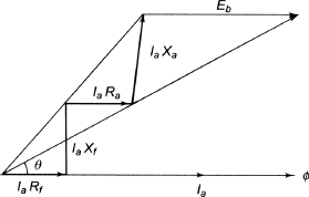
Figure 9.32 Phasor Diagram of AC Series Motor
Figure 9.33 shows speed-torque characteristics of AC and DC series motors. It will be observed that the whole performance revolves on the point that back emf in AC series motor should be made, as far as possible, equal to the back emf in DC series motor. This would mean reducing the armature and field reactances. Field reactance can be reduced by using less number of turns on the field, which will in turn reduce field flux. However, to develop the same torque, the number of turns on the armature has to be increased in the same ratio. This would reduce field reactance and increase armature reactance. To cancel the effect of armature reactance, compensating winding is used.
The power factor of a series motor is rather poor because of the large reactances of field and armature (Xf and Xa). The power factor at low speed is very poor which is due to the small value of rotational back emf, and as such applied voltage has to be balanced by field and armature reactances which will now be high. However, power factor of AC series motor is higher at higher speeds and it is about 0.95.
The arrangement of main field winding connected in series with the compensating winding for an AC series motor is shown in Figure 9.34. The axis of this winding is along the brush axis and the wind-ing must be spread over the full pitch for effective neutralisation of cross-flux. The arrangement also shows an interpole winding connected in series with the other two windings, whose effect is only over the interpolar region.
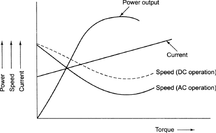
Figure 9.33 Performance Characteristic of Series Motor AC Operation
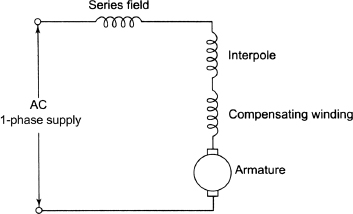
Figure 9.34 Series Motor with Compensating Winding and Interpole Winding Connected to AC Mains
The no-load speed of a universal motor is very high (about 20,000 rpm). Hence, the motor is smaller in size than other types for a given load. Universal motors are used where light weight is important as in vacuum cleaners, portable tools and so on.
9.14.3.1 Constructional features
- (i) It has less number of turns on the field and more number of turns on the armature. The number of turns on the armature is regulated by adapting lap winding and using large number of poles, especially for traction motors.
- (ii) It has compensating winding, which cancels the magnetic effect of armature current.
- (iii) Since field is weak, it has small air gap.
- (iv) To reduce transformer emf which gives commutating problem, these motors are run preferably from
 cycles for 25 cycles supply.
 - (v) These motors are suitable for maximum 400-V supply voltage.
9.15 STEPPER MOTOR
The important property of stepper motor is to convert a train of input pulses, that is, a square wave pulse, into a precisely defined increment in the shaft position where each pulse moves the shaft through a fixed angle. Therefore, stepper motor is an electromechanical device that actuates a train of step movements of shaft in response to a train of input pulses where the step movement may be angular and linear and one-to-one relationship exists between the input pulse and step movement of the shaft. The angle through which the motor turns or shaft moves for each pulse is known as the step angle which is expressed in degrees. As the step angle is dependent on the number of input pulses, the motor is suitable for controlling position by controlling the number of input pulses. Therefore, this system is used to control the position which is known as position control system. There are three types of stepper motors:
- Variable reluctance stepper motor
- Permanent magnet stepper motor
- Hybrid stepper motor
9.15.1 Variable Reluctance Stepper Motor
This is the most basic type of stepper motor and helps to explain the principle of operation of stepper motor. The stator of the motor is usually for three phases having six salient poles with concentrated exciting windings around each one of them. The stator has laminated construction and is assembled in a single stack. The number of poles of stator and rotor are different to secure the ability of the motor for bi-directional rotation and self-starting capability. The rotor is made of slotted steel laminations. Let Ns and Nr be the number of stator poles and rotor poles. For three phase, the number of rotor poles in terms of stator poles is given by
![]()
where q is the number of stator phases or stacks. Figure 9.35 shows the stepper motor having four salient-pole rotor.
The basic diagram has been shown in Figure 9.36 where the coils are wound in such a way that diametrically opposite poles are connected in series. The three phases are energised from a DC supply with the help of switches.
9.15.1.1 Operation
The operation depends on various reluctance positions of rotor with respect to stator. If one phase of the stator is excited, it produces a magnetic field. Its axis lies along the poles, the phase around which it is excited. The rotor moves in the direction of minimum reluctance and such a position indicates the position where the axis of magnetic field of stator tallies with the axis passing through any two poles of the rotor. The phases A, B and C are energised in sequence one after the other with the help of switches SW1, SW2 and SW3, respectively.
When the phase AA´ is excited with the switch SW1 closed, the magnetic axis lies along the vertical direction or along the poles formed by AA′. The rotor adjusts itself in the direction of minimum reluctance position, as shown in Figure 9.37.
Next the phase BB´ is excited with switch SW2 closed and the switch SW1 open to de-energise AA′. The stator magnetic axis shifts along the poles formed due to BB′. Now the rotor will try to align in the direction of minimum reluctance position and hence turns through an angle of 30° in the anti-clockwise direction.
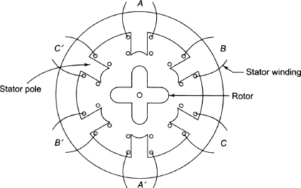
Figure 9.35 Schematic Arrangement of Variable Reluctance Stepper Motor
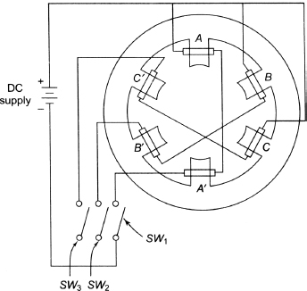
Figure 9.36 Basic Driving Circuit
.jpg)
.jpg)
.jpg)
Figure 9.37 Operation of Variable Reluctance Stepper Motor
Next the phase CC´ is excited with the switch SW3 closed and the switch SW2 open. The stator magnetic axis shifts along the poles formed due to CC´. Now the rotor will try to align in the direction of minimum reluctance position and hence turns through an angle of 30° in the anti-clockwise direction.
If we successively excite the three phases in a specified sequence, the motor takes 12 steps to complete one revolution. Let i be the current through the phase excited and L be the inductance of the relevant phase at an angle θ. The torque developed by the motor is expressed by:
![]()
From the above, we can conclude the following:
- By exciting the stator phases, it is possible to rotate the rotor in a particular direction.
- The rotor rotates in the anti-clockwise direction, if the phase sequence is A-B-C-A....
- The rotor rotates in the clockwise direction, if the phase sequence is A-C-B-A....
- If all the three phases are excited once, the distance through which the rotor is moved is known as rotor tooth pitch.
- Rotor tooth pitch

- The step angle (as)

In the above discussion, we have seen that the rotor rotates through an angle of 30° when each phase is excited simultaneously. Now if two phases are excited simultaneously, that is, AA' and BB', the stator magnetic field axis shifts to a mid-position rather than along BB' resulting in the rotor being aligned along it, that is, through an angle of 15°. Usually, the step angle is reduced by ![]() and
and ![]() . This technique is known as micro-stepping.
. This technique is known as micro-stepping.
9.15.1.2 Multi-stack stepper motor
Figure 9.38 shows the cross-sectional view of multi-stack stepper motor. For a m stack motor, the motor is divided into a number of magnetically isolated sections known as stacks along its axial length. If m is the number of stacks, that is, the number of phases, and Nr is the number of rotor poles, the step angle is given by
![]()
Following are the advantages of variable reluctance induction motor:
- High torque-to-inertia ratio
- Fast dynamic response
Figure 9.38 Cross-sectional View of Multi-stack Stepper Motor
- High rates of acceleration
- Simple and low cost
- Efficient cooling arrangement
- Robust rotor construction due to absence of brushes
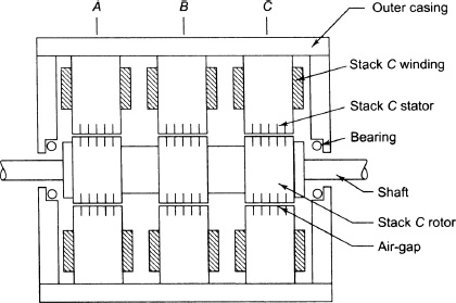
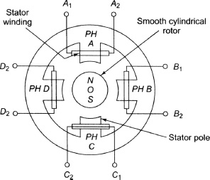
Figure 9.39 Four-phase Permanent Magnet Stepper Motor
9.15.2 Permanent Magnet Stepper Motor
This type of motor has multi-polar stator, as shown in Figure 9.39, having four stator poles. The exciting coils are wound around the poles. The number of slots per pole per phase is usually taken as one in such multi-polar machines.
The rotor is generally taken as cylindrical pole type, but it may be salient or smooth cylindrical type. The rotor is made of ferrite material which is permanently magnetized, and hence this motor is called permanent magnet stepper motor. Figure 9.40 shows the basic driving circuit for four-phase permanent magnet stepper motor to provide the voltage pulses to the stator winding of stepper motor, as shown in Figure 9.39.
Just after the application of the voltage pulses to various phases with the help of driving circuit, the rotor starts rotating through a step for each input voltage pulse. After closing the switch SW1 to excite phase A, we get N pole in phase A and the rotor starts to rotate in such a way that the magnetic axis of the permanent magnet rotor adjusts with the magnetic axis of stator as depicted in Figure 9.37(a). Next phase B is excited after closing the switch SW2 and disconnecting phase A. The rotor further adjusts its own magnetic axis with N poles of phase B. Therefore, it rotates through an angle of 90°, as shown in Figure 9.37(b). Similarly, if the phases C and D are excited, the rotor rotates through an angle of 90° in clockwise direction for excitation of each phase. Therefore, repetition of such sequence results in a step motion of a permanent magnet stepper motor. The major disadvantage of stepper motors is that they cannot be constructed with permanent magnet rotors with large number of poles and small steps are not possible. In order to overcome this, variable reluctance type stepper motor is used.
9.15.3 Hybrid Stepper Motor
The hybrid stepper motor is based on the principles of the permanent magnet and variable reluctance stepper motors. The rotor flux in hybrid stepper motor is generated by the permanent magnet and is directed by the rotor teeth to the appropriate parts of the air gap. The permanent magnet that is placed in the middle of the rotor is magnetised in the axial direction. Each pole of the magnet is surrounded by soft-toothed laminations. Figure 9.41 shows the construction of hybrid stepper motor.
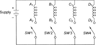
Figure 9.40 Basic Driving Circuit for Permanent Magnet Four-phase Stepper Motor
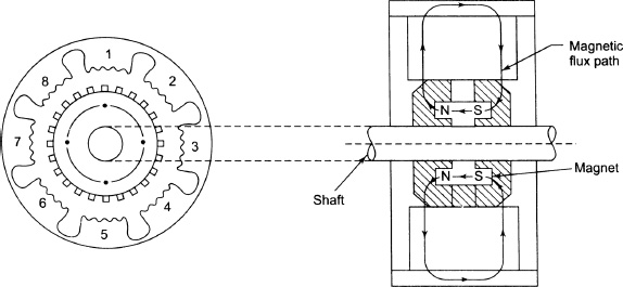
Figure 9.41 Hybrid Stepper Motor
There are generally eight poles on the stator and each pole has between two and six teeth and there is two-phase winding. The coils on poles 1, 3, 5 and 7 are connected in series to form phase A, whereas coils on poles 2, 4, 6 and 8 are connected in series to form phase B. If phase A carries positive current, stator poles 1 and 5 become South while 3 and 7 become North. Therefore, the rotor teeth with South and North polarity align with the teeth of stator poles 3 and 7 and 1 and 5, respectively. If phase B is excited and phase A is de-energised, the rotor will move by one quarter of tooth pitch. Torque is produced in a hybrid motor due to interaction of stator- and rotor-produced fluxes. Since the rotor field is produced by permanent magnet, it remains constant. Hence, the motor torque is proportional to the phase current. Following are advantages of the hybrid stepper motor:
- Step angle is very small. It is 1.8°.
- Higher torque per unit volume. It is greater than that of reluctance motor.
- There is some detent torque due to the permanent magnet.
9.16 CHARACTERISTICS OF STEPPER MOTORS
The characteristics of stepper motor are classified as follows:
- Static characteristic
- Dynamic characteristic
Torque displacement characteristic and torque current characteristic are known as static characteristic, as shown in Figure 9.42.
The torque stepping rate characteristic is known as dynamic characteristic, as shown in Figure 9.43.
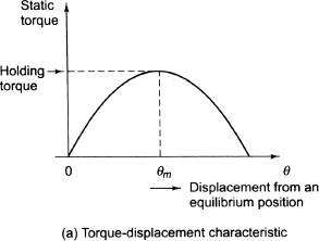
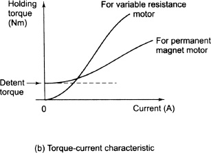
Figure 9.42 Static Characteristic
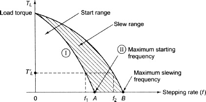
Figure 9.43 Dynamic Characteristic
9.17 DC SERVOMOTORS
DC motor converts electrical energy to mechanical energy. The motor is the opposite of a generator though a DC motor can be used both as a generator and as a motor.
AC motors have the following disadvantages:
- (i) Non-linear characteristic.
- (ii) Difficult to control its position through continuous speed or torque changes.
- (iii) These disadvantages are absent in DC motors. The disadvantages of DC motors are as follows:
- (iv) Maximum torque is limited by commutation and not by heating as with other motors.
- (v) During collection of armature current by brush through commutator, arcing occurs. In course of time, this sparking causes pitting. Modern science has advanced a lot to reduce wear and tear and maintenance costs.
- (vi) Brush and commutator requirement makes the DC motor expensive.
- (vii) A basic requirement for motor is high torque and low inertia (mass) or a high torque-to-inertia ratio. This is achieved by reducing diameter and increasing length. Again modern technology has produced low-weight rotors, ironless rotors and electronic rotors.
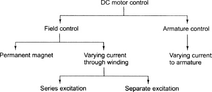
Figure 9.44 Excitation of DC Servomotors
9.17.1 Excitation of DC Servomotors
Figure 9.44 shows armature and field control of DC motor. Table 9.1 compares armature and field control of DC motor.
9.17.2 Armature-controlled DC Servomotor
Figure 9.45 shows an armature-controlled DC motor. Control signal is applied to the armature terminals.
Let
| Ra | be the armature resistance in ohm, |
| La | be the inductance of armature in henry, |
| ia | be the armature current, |
| if | be the fi eld current, |
| ea | be the applied voltage, |
| eb | be the motor torque and |
| J, f | be the inertia and friction parameters of the motor and load, respectively. |
Table 9.1 Comparison of Armature and Field Control of DC Motor
| Armature Control | Field Control |
| • Large amount of current is required as the source has to meet the full power requirements of motor | • Requirement of current is small |
| • Back emf provides damping | • Damping has to be provided by motor and load |
| • Time constant on account of inductance of winding is less | • Time constant will be more because large winding is required to produce the necessary flux |
| • Speed of response of motor to changing current is fast | • Speed of response to changing current is slow |
| • Easy to provide constant fi eld current | • Diffi cult to provide constant current to armature because of back emf |
| • Effi ciency is high | • Effi ciency is low |
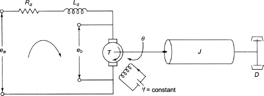
Figure 9.45 Equivalent Diagrams of Armature-controlled DC Servomotor
- Air gap flux (Φ) is proportional to if

i.e.,

- Torque is proportional to flux (Φ) and armature current (ia).


- Back end (eb ) is proportional to speed.
![]()
Applying KVL to armature circuit, we have:
![]()
The load torque equation is given by
![]()
To find ![]() , let us take Laplace transform of Equations (9.29), (9.30) and (9.31).
, let us take Laplace transform of Equations (9.29), (9.30) and (9.31).
From Equation (9.29), we have:
![]()
From Equation (9.30), we have:
![]()
From Equation (9.31), we have:
![]()
From Equation (9.33), we have:
![]()
Putting the value of Eb (s) in Equation (9.35), we have:
![]()
Substituting Ia (s) into Equation (9.34), we have:
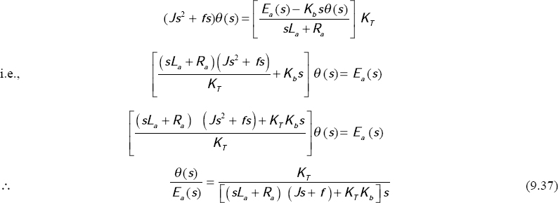
From Equation (9.37), we get:
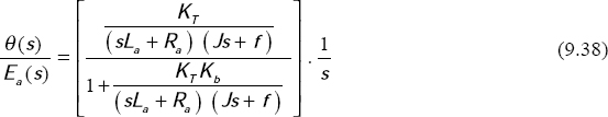
The block diagram of Equation (9.38) is shown in Figure 9.46.
In Equation (9.37) if La is small, neglecting La we have:
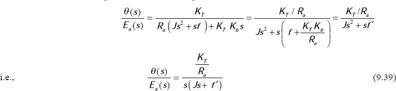
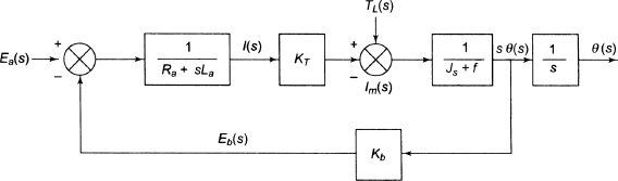
Figure 9.46 Block Diagram of Armature-controlled DC Motor
where
![]()
Equation (9.39) can also be written as:
![]()
where
![]()
and
![]()
9.17.3 Field-controlled DC Servomotors
Figure 9.47 shows field-controlled DC servomotor. In this figure,
Rf is the fi eld winding resistance in ohm,
Lf is the fi eld winding inductance in henry,
ef is the fi eld-controlled voltages in volt,
if is the fi eld current in ampere,
TM is the torque developed by the motor N-m,
J is the equivalent moment of inertia of motor and load referred to motor shaft in kg-m2,
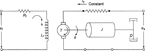
Figure 9.47 Field-controlled DC Servomotors
f is the viscous coeffi cient of motor and load referred to motor shaft in ![]() and
and
θ is the angular displacement of motor shaft in radiation. Since armature current is fed from a constant current source in the field-controlled motor, we have
The field circuit equation is expressed by:
![]()
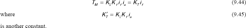
The torque equation is expressed by:
![]()
Taking Laplace transform of Equations (9.46) and (9.47) and assuming zero initial conditions, we have
![]()
and
![]()
From Equations (9.48) and (9.49), we have
![]()
![]()
where![]() is the motor gain constant,
is the motor gain constant, ![]() time constant of field circuit and
time constant of field circuit and![]() = mechanical time constant.
= mechanical time constant.
Figure 9.48 shows block diagram of field-controlled DC motor, as shown in Figure 9.47.
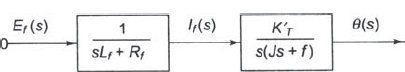
Figure 9.48 Block Diagram of Field-controlled DC Motor
9.18 AC SERVOMOTORS
An AC servomotor is basically a two-phase induction motor, as shown in Figure 9.49. A two-phase servomotor differs from a normal induction motor as follows.
The rotor of the servomotor is built with high resistance so that its X/R ratio is small and the torque- speed characteristic is nearly linear in contrast to the highly non-linear characteristic with large X/R ratio. Conventional induction motor with high X/R ratio is used for servo applications, but because of the positive slope for part of the characteristic, the system using such a motor becomes unstable. The rotor construction is usually squirrel cage or drag-cup type having small diameter to reduce inertia.

Figure 9.49 Two-phase AC Motor
The two-phase AC motor has two windings at right angles to each other and the two windings are supplied with voltages with 90° phase difference through a capacitor. The diameter of the rotor is small but the length of the rotor is long to reduce inertia for faster motor response. The frequency is normally 50 or 400 Hz. Voltage whose amplitude can be varied but of the same frequency is applied to the other winding. The flux will be rotating at the frequency of supply at synchronous speed ![]() This rotating flux cuts to produce a varying flux and reacts with the stator flux causing the rotor to rotate in a smooth manner. From the speed-torque curve, the stall torque Ts = Kmec
This rotating flux cuts to produce a varying flux and reacts with the stator flux causing the rotor to rotate in a smooth manner. From the speed-torque curve, the stall torque Ts = Kmec
![]()
Km is different for different ec
![]()
As in the case of DC motors,
![]()
i.e.,
![]()
Figures 9.50 and 9.51 show flux by control and reference winding and torque-speed characteristic, respectively.
Transfer function,
![]()
K = Km / D = motor gain constant
Tm =J/D = motor time constant
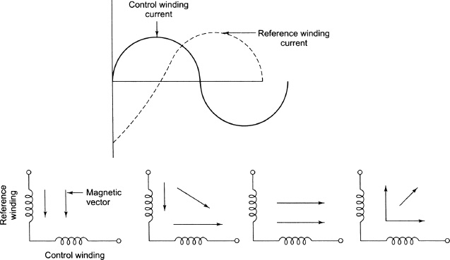
Figure 9.50 Flux by Control and Reference Winding
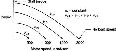
Figure 9.51 Torque-speed Characteristic
The block diagram is shown in Figure 9.52.
D is the viscous damping coefficient due to motor and load. The damping is high if the slope of the T-ω curve is steep. For Tm s|< < 1, the servomotor acts as an integrator![]()

Figure 9.52 Block Diagram
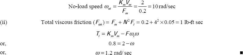
Example 9.3 An AC servomotor has both windings excited with 115V AC. It has a stall torque of 2 lb ft and its coefficient of viscous friction is 0.2 lb ft sec.
- (i) Determine its no-load speed.
- (ii) It is connected to a constant load of 0.8 lb-ft and the coefficient of viscous friction of 0.05 lb-ft sec. through a gear pass with a ratio of 4. Calculate the speed at which the motor will run.
9.19 SERVOMECHANISM
Servomechanism is a power amplifying feedback control system. The controlled variable in it is a mechanical position or time derivative of position such as velocity and acceleration.
The essential parts of servomechanism are as follows:
- (i) A transducer to convert angular position to an electrical signal.
- (ii) An amplifier to improve the signal strength.
- (iii) Device to develop torque such as motor.
- (iv) Devices to transmit torque to load such as gears.
9.19.1 Positional Servomechanism
In a positional servomechanism, the position of the load must be maintained both under steady-state and transient conditions.

Figure 9.53 Positional Servomechanism
In Figure 9.53,
| θr(t) | is reference angular position, rad |
| er | is input reference voltage at which the marked position of load is placed |
| ef | is feedback voltage due to feedback gear angular position |
| e | is error signal = eR – ef |
| Ka | is gain of servoamplifier |
| Km | is motor constant lb-ft or N-m/V or A |
| Jm | is motor inertia, kg-m2 |
| Dm | is damping friction of motor in N-m/rad/s |
| Nm | is gear teeth of motor |
| θm | is motor shaft angular position in rad |
| Nt | is gear teeth of load |
| Jl | is moment of inertia of load kg-m2 |
| Dl | is damping viscous friction of load N-m/rad/s |
| rl | is additional torque on load |
| Nf | is gear teeth of feedback |
| θf | is angular position of feedback gear in rad |
The two potentiometers must be identical in their electrical characteristics and connected in parallel with their positions set at the initial marked position of load. Figure 9.54 shows the block diagram of a servomotor.
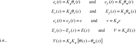
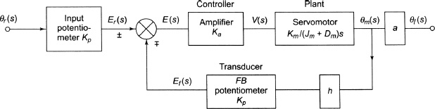
Figure 9.54 block diagram of sevometer
![]()
Gear train to feedback
![]()
It is possible to transfer the load due to feedback gear to the motor as follows:
![]()
If we include the load,
![]()
Since we are interested to feedback loop only, we can write:
The block diagram is reduced, as shown in Figure 9.55.
The servomotor may be either DC or two-phase AC servomotor. In a DC motor, the armature voltage is controlled by a DC amplifier and the field is provided by a permanent magnet.
Figure 9.56 shows the waveform diagram.
In AC system, the reference voltage is AC and the amplifier is an AC amplifier. The motor demodulates the signal so that the feedback signal is DC. The final waveform θl (s) will be same as for DC.
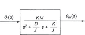
Figure 9.55 Reduced Block Diagram of a Servomotor
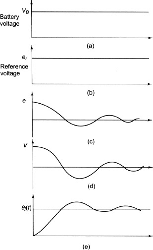
Figure 9.56 Waveform of a Servomotor
9.19.2 Rate Servomechanism
The derivative of the position, that is, velocity, is monitored and kept constant here, having velocity as the controlled variable. Figure 9.57 shows the schematic diagram of a rate servomechanism.
The system consists of a motor whose shaft speed θ(ω) is to be held constant, the load attached to the shaft, a tachometer coupled to the motor shaft whose generated voltage is fed along with reference voltage and the difference error voltage amplified and applied to the DC motor to correct it to the desired speed.
Taking the input-output relationship of each block, for the amplifier block, output voltage is given by
![]()
For the tachometer,

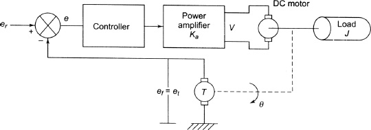
Figure 9.57 Rate Servomechanism
where Ka is the amplifier gain and Kg is tachometer constant
![]()
The torque developed by the motor must be equal to the torque due to inertia and damping.
![]()
Solving for er we have:
![]()
In the steady state ![]() therefore, we have,
therefore, we have,
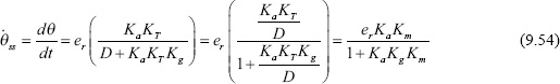
where![]() is called the velocity gain constant which relates steady-state motor speed to armature voltage and hence is a velocity gain. Its unit is (rad/s)V The time constant (τc) of the closed-loop system is defined by:
is called the velocity gain constant which relates steady-state motor speed to armature voltage and hence is a velocity gain. Its unit is (rad/s)V The time constant (τc) of the closed-loop system is defined by:
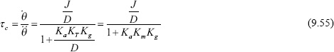
where KaKmKg is the open-loop gain.
If KaKmKg is very large, or, KaKmKg 1, we get, from Equation (9.54):
![]()
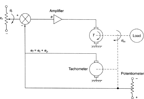
Figure 9.58 Damping by Derivative Feedback
The steady-state speed depends only on input voltage and the characteristic of the tachometer.
9.19.3 Damping by Derivative Feedback
The slope of the speed-torque curve gives the viscous damping or damping coefficient. The feedback introduced by the voltage generated by a tachometer is a derivative feedback as Vg = Kgw. Figure 9.58 shows damping by derivative feedback.
The error voltage is given by
![]()
Equating the torques, we get:
![]()
Kd is the amplifier gain of the voltage from tachometer.
Solving θr
![]()
where K = KaKmKg is the open-loop gain.
Damping ratio from the second-order Equation (9.58) after dividing throughout by J/K is
![]()
![]()
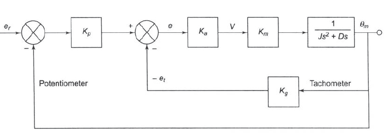
Figure 9.59 Block Diagram
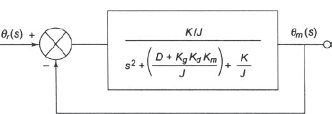
Figure 9.60 Simplified Block Diagram
For potentiometer alone, we can write:

Therefore, damping ratio is increased by KgKdKm by feeding back negatively the tachometer voltage. Figure 9.59 shows the block diagram.
If we take Laplace transform of Equation (9.58), we get
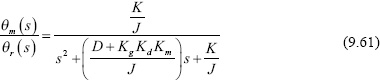
Figure 9.60 shows simplified block diagram of Equation (9.61).
Example 9.4 Figure E9.1 shows a schematic diagram of an automatic control system where the angular position of an antenna is controlled.
The system has the following data:
The gear ratio (N1/N2) = 0.1, voltage gain of the amplifier (A) = 1,000
Motor torque constant = 0.25 N-m/A of field current
Field winding resistance (Rf) = 20 ohm
Self-inductance of winding (Lf) = 1 H
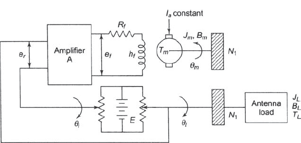
Figure E9.1
Error detector sensitivity = 0.02 V/1° error
Moment of inertia of load (JL) = 50 × 10-6 kg-m2
Moment of inertia of motor (JM) = 0.5 × 10⁻⁶ kg-m2
Viscous friction coeffi cient of load (BL) = 0.9 × 10⁻⁵ N-m/rad/s
Viscous friction coeffi cient of motor (Bm) = 0.1 × 10⁻⁷ N-m/rad/s
Determine the transfer function relating input displacement θi and output displacement θ0.
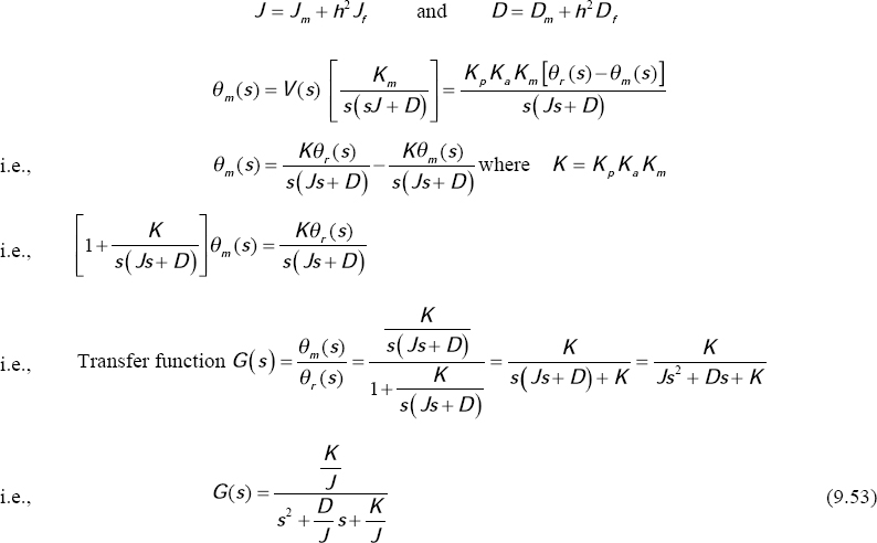
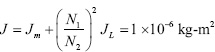
![]()
Equivalent moment of inertia referred to motor shaft is
Similarly, equivalent viscous friction referred to motor shaft is
![]()
Figure E9.2 shows the block diagram of the system.
The open-loop transfer function is given by
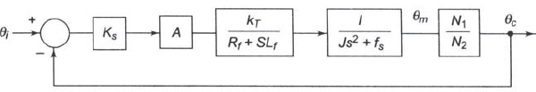
Figure E9.2
The closed-loop transfer function is given by
![]()
SIGNIFICANT POINTS
The slip (sf) of the rotor with respect to the forward rotating field is given by
![]()
where ns and n are the synchronous speed and rotor speed, respectively.
The slip (sb) of the rotor with respect to the backward rotating field is given by
Equivalent impedance(Zf) of imaginary rotor due to forward rotating field is

and the equivalent impedance (Zb) of imaginary rotor due to backward rotating field is
If Pgf and Pgb are the air gap power due to forward and backward field, respectively, we can write:
The torque due to forward field is given by
![]()
Again, the torque due to backward field is given by
![]()
where ωs represents the synchronous speed.
The resultant torque is given by
![]()
The Cu loss of the single-phase motor is given by
![]()
where Prf and P rb are the Cu loss of the rotor due to forward and backward field, respectively.
The mechanical power developed in induction motor is given by
![]()
Shaft output power is given by
where
![]()
SHORT QUESTIONS AND ANSWERS
Q.1 How are the 1-phase AC motors made self-starting?
Ans. 1-phase AC motors are made self-starting by providing auxiliary winding in parallel with main winding.
Q.2 Where and why is a centrifugal switch used in a split-phase motor?
Ans. It is placed on the shaft of the rotor and electrically connected with the auxiliary winding. When the motor achieves 70 to 80 per cent of its synchronous speed, it disconnects the auxiliary winding.
Q.3 What types of windings are used in split-phase motor?
Ans. Double-layer chain or concentric type winding is used in split-phase motor.
Q.4 Why and where is a capacitor used in the one-phase AC motor?
Ans. It is used in series with the auxiliary winding to give a phase displacement between starting and main winding so that starting torque is improved.
Q.5 What type of rotor is used in a capacitor-start motor?
Ans. Squirrel cage rotor is used in a capacitor-start motor.
Q.6 How can the direction of rotation of capacitor-start motor be reversed?
Ans. By reversing either the running or starting winding that leads to the supply lines, the direction of rotation of a capacitor-start motor can be reversed.
Q.7 What is a permanent capacitor motor?
Ans. It is a one-phase AC motor having two windings and a permanent capacitor. It has no centrifugal switch.
Q.8 State the uses of permanent capacitor motors?
Ans. Permanent capacitor motors are used for ceiling fans and table fans where starting torque is not high.
Q.9 What is a shaded-pole motor?
Ans. It is a single-phase AC motor. A portion of the stator core is encircled by a copper ring.
Q.10 What type of row is used in capacitor-start capacitor-run shaded-pole motor?
Ans. Squirrel cage rotor is used in capacitor-start capacitor-run shaded pole motor.
Q.11 What is a universal motor? Why is it called so?
Ans. The 1-phase fractional horse power motors ranging from ![]() HP in which field winding and armature windings are connected in series are called universal motors. Since these motors can
HP in which field winding and armature windings are connected in series are called universal motors. Since these motors can
be used with both DC and AC supply, they are called universal motors.
SUPPLEMENTARY PROBLEMS
- The constants of a 1/4-HP, 230-V, 4-pole, 50-Hz, single-phase induction motors are as follows:
The total load is such that the machine runs at 3 per cent slip, when the applied voltage is at 210 V. The iron losses is 35.5 W at 210 V Find the following:
(a) input current, (b) power developed, (c)shaft power (if mechanical losses are 7 W) and (d) efficiency[Ans. (a) 1.8586 A, (b) 166.2 W, (c) 159.2 W, (d) 62.85%]
- A 230-V, 380-W, 4-pole, single phase induction motor gave the following test results:
No-load test: 230V 84W 2.8A
Blocked rotor test: 110V 460W 6.2AThe stator winding resistance is 4.6 Q and during the blocked rotor test, two auxiliary windings are kept open. Determine the equivalent circuit parameters?
[Ans. R1 = 4.6 Ω, R′2 = 7.067 Ω, X 1 = X′2 = 6.68 Ω, Xm = 143.75 Ω]
MULTIPLE-CHOICE QUESTIONS AND ANSWERS
- In a double revolving field theory of single-phase induction motor, if the slip of the forward motor is s, then the slip of backward motor is
(a) 2s (b) s ( c) 2 - s (d) s - 2 - In case of a split-phase motor, the phase shift between current in two windings is around
(a) 30° (b) 70° (c) 90° (d) 120° - Which one of the following capacitor-start split-phase motor will have the largest value of capacitance?
- Compared with a resistor split-phase motor, a capacitor-start motor has
(a) higher starting torque (b) lower starting torque
(c) higher running torque (d) lower running torque - If a capacitor-start induction motor is switched on to supply with its capacitor replaced by an inductor of equivalent reactance, the motor will
(a) not start at all (b) start and run at rated speed
(c) start and run slowly (d) start with humming noise - Capacitor-start capacitor-run induction motor is basically a
(a) AC series motor (b) two-phase motor
(c) synchronous motor (d) commutator - The main drawback of two capacitor-type induction motor is
(a) low power factor (b) poor starting torque
(c) pulsating torque (d) high cost - In comparison with resistance-start induction motor, the permanent capacitor motor,
(a) has better power factor (b) is more expensive
(c) has better starting torque (d) all of these - In comparison with capacitor-start capacitor-run motor, the permanent capacitor motor has
(a) poor power factor (b) poor starting torque
(c) simple construction and low cost (d) all of these - The rotating magnetic field in a shaded pole motor is developed by using
(a) shading coils (b) salient poles
(c) a capacitor (d) damper windings - The phase splitting in a shaded pole motor is obtained by placing a shading coil at the slot cut around the
(a) smaller part of the hole (b) larger part of the hole
(c) both the parts of the hole (d) any of the above - In a shaded pole motor, shading coils are used to
(a) reduce winding losses (b) reduce friction losses
(c) produce rotating magnetic field (d) protect against sparking - In a shaded pole squirrel cage induction motor, the flux in the shaded part always
(a)leads the flux in the unshaded pole segment
(b)is in phase with the flux in the unshaded pole segment
(c)lags the flux in the unshaded pole segment
(d)none of the above - Consider the following statements regarding fractional horse power shaded pole motor:
1. Its direction of rotation is from unshaded to shaded portion of the poles.
2. Its direction is from shaded to unshaded portion of the poles.
3. It can remain stalled for short periods without any harm.
4. It has a very poor power factor.
Of these statements
(a) 1, 3 and 4 are correct (b) 2, 3 and 4 are correct
(c) 2 and 4 are correct (d) 1 and 4 are correct - The direction of shaded pole motor can be reversed by
(a) reversing supply terminals
(b) shifting any shading coil to the other half of the pole
(c)shifting two shading coils to the other half of the pole
(d)shifting all the shading coils to the other half of the pole - The wattage rating for a ceiling motor will be in the range
(a) 50 to 250 W (b) 250 to 500 W (c) 50 to 150 W (d) 10 to 20 W - What will happen if a single-phase supply is connected to an ordinary DC series motor?
(a) It will not run at all (b) It will run, but not satisfactorily
(c) The armature will burn out (d) The field winding will burn out - AC series motors are built with as few field turns as possible to reduce
(a) flux (b) eddy current losses (c) reactance (d) speed - A universal motor runs at
(a) higher speed with DC supply and with less sparking
(b) higher speed with AC supply and with less sparking
(c) same speed with both AC and DC supplies
(d) higher speed with AC supply but with increased sparking at the brushes - Speed of a universal motor is
(a) dependent on frequency of supply (b) proportional to frequency of supply
(c) independent of frequency of supply (d) none of the above - The speed of a universal motor can be controlled by
(a) introducing a variable resistance in series with the motor
(b) tapping the fields at various points
(c) centrifugal mechanism
(d) all of the above - 14. In repulsion motors, brush angle with respect to magnetic axis is kept at
(a) 0° to 15° (b) 15° to 45° (c) 90° (d) 180° - The torque-speed characteristic of a repulsion motor resembles which of the following DC motor characteristic?
(a) separately excited (b) shunt (c) series (d) compound - In a single-phase repulsion motor power factor is
(a) always leading (b) high at low speed (c) high at high speed (d) always unity - In a single-phase repulsion motor by shifting the brush position
(a) speed and direction of rotation can be controlled
(b) only speed can be controlled
(c) speed, torque and direction of rotation can be controlled
(d) only torque can be controlled by varying the speed at constant output power