▶ 12.2 Internet Transport Protocols
The “hourglass” diagram in Chapter 10 (Figure 10.17) illustrates how internet protocols support a broad range of networking technologies at the bottom and a broad range of applications at the top. Almost all of these rely on the standard network and transport protocols. IP provides global addressing for internet hosts. TCP and the User Datagram Protocol (UDP) provide data transport between processes on any two of those hosts.
Both TCP and UDP headers carry port numbers that indicate the process sending or receiving the packet at a host. Often the port numbers connect client processes to server processes. When a client opens a connection to a particular server, the client’s protocol stack randomly selects the source port. The destination port is chosen according to the application protocol being used; port 80 is traditionally used for web traffic, while port 25 is used to send an email.
User Datagram Protocol
Not all network traffic requires reliable connections. If a particular application simply needs to exchange unreliable datagrams, we don’t use TCP, because it involves unnecessary overhead and possible delays. Some application protocols inherently detect lost or damaged packets and retransmit them as needed. These application protocols use UDP instead of TCP. FIGURE 12.1 displays the contents of the UDP header.

FIGURE 12.1 UDP packet fields.
FIGURE 12.2 shows a UDP header expanded in Wireshark. As with other simple headers, we learn very little of interest by expanding the header. The principal information is in the port numbers.

FIGURE 12.2 UDP header displayed in Wireshark.
© Wireshark Foundation
Some might wonder why we should bother having a UDP format at all; it would seem that an application could simply use the IP header itself. The UDP header primarily provides source and destination port numbers. The protocol stack uses port numbers to associate TCP connections with processes; UDP allows it to use the same strategy to deliver UDP packets to processes.
End-to-End Transport Protocols
TCP and UDP are purely end-to-end protocols. No conventional internet router or other intermediate node needs to pay attention to transport headers or those beyond it inside the packet. FIGURE 12.3 illustrates this clearly; routers do not require a protocol layer above IP in order to carry traffic between networks.

FIGURE 12.3 Routing and internet protocol layering.
In practice, certain types of network devices do pay attention to higher layer packet headers. Firewalls and NAT devices, for example, use TCP and UDP port numbers. Large-scale sites also may use special “load balancing” routers that distribute traffic among multiple servers; these often use higher level headers to route the traffic. Network intrusion detection systems also look at multiple packet headers to try to detect an attack. (See Section 14.4.2.)
12.2.1 Transmission Control Protocol
A transport protocol uses timeouts and ACKs to ensure reliable packet delivery, and TCP is the internet protocol that ensures reliable transport. People often refer to the internet protocol stack as “TCP/IP” to acknowledge the presence of both reliable transport (TCP) and internet routing (IP). FIGURE 12.4 shows the major contents of a TCP packet.

FIGURE 12.4 Major TCP packet fields.
Here is a summary of the fields shown:
■ Source port—the port number assigned to the sending process.
■ Destination port—the port number at the receiving process.
■ Sequence number (SEQ)—number assigned to the first byte in the packet; each subsequent byte in the packet is assigned the corresponding sequential number.
■ Acknowledgment number—the sequence number of the next byte to be received from the sender.
■ Size—the size of the TCP header.
■ Status—a set of flags indicating the roles performed by this packet.
■ Window size—indicates the amount of data the sender can accept on this connection.
■ Checksum—the checksum for the TCP header and data field.
■ Urgent pointer—points to “urgent” data; rarely used.
These same fields appear in the TCP header when expanded by Wireshark. FIGURE 12.5 shows an expanded TCP header.

FIGURE 12.5 TCP header displayed in Wireshark.
© Wireshark Foundation
Sequence and Acknowledgment Numbers
The sequence and acknowledgment numbers help ensure reliable transmission of all data. The sender sequentially numbers each byte sent in a TCP connection. A packet’s SEQ field carries the sequence number of the first byte in each packet. The recipient keeps track of the sequence number of each byte received. The acknowledgment number reports the highest sequence number of all bytes received plus one. When a TCP packet acknowledges data from an earlier packet, Wireshark provides a link to that earlier packet in its “SEQ/ACK Analysis.”
There is an interesting difference between the packet’s actual contents and Wireshark’s expanded header. Sequence numbers and acknowledgment numbers are shown relative to the start of the connection. Thus, byte 1 in the connection yields sequence number 1 in the expanded Wireshark header.
In fact, when TCP opens a connection, it tries to select a random and hard-to-predict starting sequence number. In the 1990s, attacks developed against firewalls that sent privileged keyboard commands. The receiving hosts accepted the commands, because the source IP address appeared to belong to a trustworthy host. In fact, the source address was forged; the recipient accepted the packet because the attacker accurately guessed the right TCP sequence number. This tricked the recipient’s protocol stack into believing that the trusted host had sent the packet as part of an opened connection. This was called the IP spoofing attack.
Window Size
A fundamental problem in networking is that hosts never operate at exactly the same speed. One host may be a little faster at sending data than the other is at receiving data. If a host sends data too fast, the recipient may lose data as it uses up its available RAM. This is the flow control problem.
The window size tells the recipient host how many bytes the sending host may accept in return traffic. Each TCP packet a host receives will acknowledge all bytes received and report the window size: the number of additional bytes it can handle.
TCP Connections
Any connection goes through three stages: setup, operation, and termination. The Status flags in a TCP packet indicate its role in the connection. FIGURE 12.6 shows the complete history of a TCP connection as displayed by a Wireshark packet summary pane.
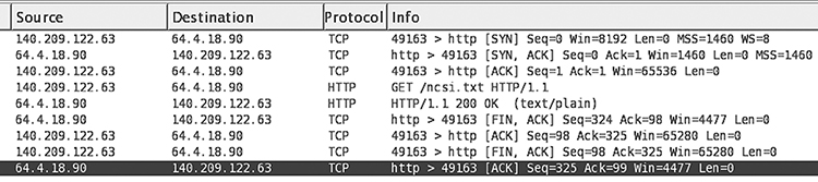
FIGURE 12.6 A TCP connection summarized by Wireshark.
© Wireshark Foundation
Now let us examine this simple connection. Because connections typically take place in a client/server environment, we will call the initiator the client and the recipient the server. The client opens the TCP connection to the server by exchanging a three-way handshake: three packets with particular Status flag settings:
■ Client sends first packet: SYN (“Synchronize”) flag set
■ Server sends second packet: both SYN and ACK flags set
■ Client sends third packet: ACK flag set
The fourth packet contains data sent by the client to the server (“GET/ncsa.txt”). The fifth packet contains data sent to the client by the server (“HTTP/1.1”). The final packets exchange the FIN (“Finish”) TCP flag to close the connection.
FIGURE 12.7 expands the contents of the TCP flags field. This particular packet has the ACK and the “Push” flags set. The “ACK” flag means that the packet acknowledges an earlier one. The Push flag indicates that the sending application is finished sending data for now.

FIGURE 12.7 TCP flags displayed by Wireshark.
© Wireshark Foundation.
Connection Timeout
Packet delivery is unreliable and host computers also are unreliable. This poses a challenge for network protocols. A host might begin a protocol exchange with another and a packet might get lost. The hosts must be able to recover, instead of waiting forever for a response.
For example, a client begins a three-way handshake, sending a SYN packet to a server. The server responds with the SYN/ACK packet. Then the client shuts down and never responds. This yields a half-open connection. The server doesn’t quite open the connection, because the final ACK never arrived. The server eventually times out the connection and discards it. Properly designed network protocols provide timeouts for all message exchanges.
12.2.2 Attacks on Protocols
When hosts perform a network protocol, they are like children playing a game while blindfolded. The players can communicate, but those wearing blindfolds can’t really tell what is happening. They are limited to spoken messages and can’t really see what the others do.
In network protocols, we try to exchange enough messages to tell the hosts what has happened. We don’t want to send messages that aren’t absolutely necessary. We optimize performance by sending fewer and smaller messages, but we also increase the risk of confusion and chaos.
The oldest internet protocols assumed that neither participant was malicious or was trying to trick the other host. Protocols were implemented in the simplest and most obvious ways. This assumption changed dramatically in the late 1980s and the 1990s.
Classic internet protocols, those developed in the early 1980s, often contained vulnerabilities. The IETF has overseen improvements in many protocols to eliminate problems and weaknesses. In other cases, we simply can’t trust the protocol unless we restrict it to a trustworthy network, or protect it with cryptography. (See Chapter 13.) Attackers have exploited protocols to perform three general types of attacks:
Exploit one host’s assets to attack a different victim host.
Use up the victim host’s resources directly.
Masquerade as another host or user.
Section 10.1.3 notes that a host’s internet connection greatly increases its attack surface. That section identified attack vectors in general terms (“worms” and “botnets”). The rest of this section introduces specific examples of attacks on network protocols.
Internet Control Message Protocol
The Internet Control Message Protocol (ICMP) provides status messages that report errors detected while routing internet packets. It also implements the typical “ping” operation and gives routers a way to redirect packets sent by hosts. ICMP packets reside inside IP packets, replacing transport packets like TCP or UDP.
Ping Attacks
To perform a “ping,” a host typically sends an ICMP Echo Request packet. The packet contains a block of data that the recipient copies into an Echo Reply and sends back to the original sender. FIGURE 12.8 illustrates such a packet displayed in Wireshark.

FIGURE 12.8 A “ping” packet shown in Wireshark.
© Wireshark Foundation
The receipt of the Echo Reply quickly shows that the hosts can reach each other and provides a simple measurement of the transmission delay. Ping has, in fact, been involved in a variety of attacks over the years, mostly causing denial of service.
■ Ping Floods
In a “ping flood,” one or more hosts conspire to flood a victim with ping requests. The flood of requests keeps the victim’s protocol stack and network very busy. Any ping responses the host produces will simply add to the network’s congestion. Some networks block pings, or all ICMP messages, to avoid such attacks.
■ Smurf Attack
This is a variant of the ping flood in which a single attacker tricks other hosts into attacking the victim. The result is a ping flood, engulfing the victim in a DDOS attack. The attacker sends a forged ping request packet; the source host address points at the victim, not the attacker. The destination is a broadcast address. This sends the ping request to every computer that receives the broadcast. Thus, every one of these computers sends a ping reply at the victim. The attacker can overwhelm the victim by sending a steady stream of such packets, prompting a continuing flood directed at the victim.
Internet routing standards expect gateways to discard broadcast packets. This should limit smurf attacks to internal sources. Moreover, hosts often are configured to ignore ping requests sent to broadcast addresses.
■ Ping of Death
The “ping of death” is not actually a protocol weakness. It was caused by mishandling of too-large messages, so it was a form of buffer overflow error. The weakness persisted in many protocol stacks until the late 1990s, because it relied on a series of circumstances that never occurred in typical operation. The problem disappeared as protocol stacks were patched to correct the flaw.
Redirection Attacks
ICMP provides error messages so that a router can direct traffic away from itself and toward a different host. Routers may transmit such messages if there are two or more routers visible to the host, but the host sends some of its traffic to the wrong one.
Once an attacker redirects traffic away from the correct router and toward a subverted host, the attacker can intercept, examine, and modify the victim’s network traffic. This allows the attacker to take over a victim’s TCP connections and masquerade as the victim host or its user.
TCP/IP Attacks
Even though it is simple to forge the source IP address of a UDP packet, it is much harder to believably forge the source of a TCP packet. In general, attackers shouldn’t be able to hijack a connection unless they subvert a router that carries the connection’s traffic.
■ SYN Flood Attack
The attacker sent a series of SYN packets to the victim, each specifying a different socket. The source addresses were usually forged, because there was no need to process the responses. Each SYN packet produced a half-open connection. The connection persisted until the protocol stack timed it out.
The attack was very effective when it first emerged in 1996, because victim hosts only had a small number of data structures to handle incoming connections, and those were very quickly used up. Attackers sent SYNs much faster than the victim host would detect and close the half-open connections.
The general solution was to improve management of half-open connections. For example, some hosts would discard and reuse the oldest half-open connection if another request came in.
■ Source Routing Attack
This is a clever variant of the redirection attacks just noted: The IP header contains an option for “source routing,” which allows the sender to direct the traffic through a series of hosts. The attacker forges a packet from a trustworthy host and puts the attacker’s host on the packet’s route. The attacker directs the packet at the victim. The victim typically will respond using the source route provided in the original packet. This takes the packet back to the attacker’s host, enroute to the trustworthy host. The attacker’s host simply processes the packet and doesn’t forward it further.
There are various approaches to address this risk. For example, hosts might want to discard source routing information when talking to a trusted host. More often, however, we want to rely on cryptographic authentication of the trusted host, which we see in Chapter 13.
■ IP Spoofing Attacks
In general, “IP spoofing” refers to any attack that forges the sender’s IP address. In an earlier section, we examined a particular spoofing attack that relied on predicting TCP sequence numbers. The attack attempted to send the minimum number of packets necessary to open a connection and provide data; in this case, a series of keyboard commands that enabled the attacker to penetrate the victim host. Because the source address belonged to a trusted host and the sequence numbers looked correct, the victim accepted the data as a legitimate keyboard command from the trusted host.
In a practical attack, the attacker may open other connections with the victim host to detect the pattern by which the host assigns sequence numbers. Then the attacker floods the victim with packets, each containing a guess at the correct sequence number. Traditionally, the erroneous packets were simply discarded, while the correctly guessed packet was accepted.