
4
The Boot-Up Procedure
Now that the mechanisms, tools, and methodologies are in place, it is finally time to start looking at the procedures required to run the software on the target. Booting up an embedded system is a process that often requires knowledge of the specific system and the mechanisms in play. Depending on the target, there are a few indications we need to look for in the manual to find out what the system expects from the developer to successfully boot executables from the flash memory. This chapter will focus on the description of the boot process, with emphasis on the case of the Cortex-M microcontroller, which we decided to use as a reference platform. In particular, we will cover the following topics:
- The interrupt vector table
- Memory layout
- Building and running the boot code
- Multiple boot stages
By the end of this chapter, you will have an overview of main-loop embedded development.
Technical requirements
You can find the code files for this chapter on GitHub at https://github.com/PacktPublishing/Embedded-Systems-Architecture-Second-Edition/tree/main/Chapter4.
The interrupt vector table
The interrupt vector table, often abbreviated to IVT or simply IV, is an array of pointers to functions associated by the CPU to handle specific exceptions, such as faults, system service requests from the application, and interrupt requests from peripherals. The IVT is usually located at the beginning of the binary image and thus is stored starting from the lowest address in the flash memory.
An interrupt request from a hardware component or peripheral will force the CPU to abruptly suspend the execution and execute the function at the associated position in the vector. For this reason, these functions are called interrupt service routines (or simply ISRs). Runtime exceptions and faults can be handled in the same way as hardware interrupts, so special service routines are associated with internal CPU triggers through the same table.
The order of the ISRs enumerated in the vector, and their exact positions depend on the CPU architecture, the microcontroller model, and the peripherals supported. Each interrupt line corresponds to a predefined interrupt number and, depending on the microcontroller features, may be assigned a priority.
In a Cortex-M microcontroller, the first 16 positions in memory are reserved for storing the pointers to system handlers, which are architecture-dependent, and associated to different types of CPU runtime exceptions. The lowest address is used to store the initial value of the stack pointer, and the next 15 positions are reserved for system services and fault handlers. However, some of these positions are reserved and not connected to any event. The system exceptions that can be handled using separate service routines in a Cortex-M CPU are as follows:
- Reset
- Non-Maskable Interrupt (NMI)
- Hard fault
- Memory exception
- Bus fault
- Usage fault
- Supervisor call
- Debug monitor event
- PendSV call
- System tick
The order of the hardware interrupts, starting from position 16, depends on the microcontroller configuration and, thus, on the specific silicon model, as the interrupt configuration refers to specific components, interfaces, and external peripheral activities.
A fully populated vector of external interrupt handlers for STM32F407 and LM3S targets can be found in this book’s code repository.
Startup code
In order to boot a workable system, we need to define the interrupt vector and associate pointers with defined functions. A typical startup code file for our reference platform places the interrupt vector in a dedicated section using the GCC section attribute. As the section will be put at the beginning of the image, we must define our interrupt vector starting with the reserved space for the initial stack pointer, followed by the system exception handlers.
The zeros correspond to the positions of the reserved/unused slots:
__attribute__ ((section(".isr_vector")))
void (* const IV[])(void) =
{
  (void (*)(void))(END_STACK),
  isr_reset,
  isr_nmi,
  isr_hard_fault,
  isr_mem_fault,
  isr_bus_fault,
  isr_usage_fault,
  0, 0, 0, 0,
  isr_svc,
  isr_dbgmon,
  0,
  isr_pendsv,
  isr_systick,
From this position on, we define the interrupt lines for the external peripherals as follows:
  isr_uart0,
  isr_ethernet,
  /* … many more external interrupts follow */
};
The startup code must also include the implementation of every symbol referenced in the array. The handler can be defined as void procedures with no arguments, in the same format as the signature of the IV:
void isr_bus_fault(void) {
  /* Bus error. Panic! */
  while(1);
}
The interrupt handler in this example never returns, as a result of an unrecoverable bus error, and hangs the system forever. Empty interrupt handlers can be associated to both system and external interrupts using weak symbols that can be overridden in the device driver modules by simply defining them again in the relevant code section.
Reset handler
When the microcontroller is powered on, it starts the execution from the reset handler. This is a special ISR that does not return but rather performs initialization of the .data and .bss sections, and then calls the entry point of the application. The initialization of the .data and .bss sections consists of copying the initial value of the variables in the .data section in flash onto the actual section in RAM where variables are accessed at runtime and filling the .bss section in RAM with zeros so that the initial value of static symbols is guaranteed to be zero as per C convention.
The source and destination addresses of the .data and .bss sections in RAM are computed by the linker when generating the binary image and exported as pointers using the linker script. The implementation of isr_reset may look similar to the following:
void isr_reset(void)
{
  unsigned int *src, *dst;
  src = (unsigned int *) &_stored_data;
  dst = (unsigned int *) &_start_data;
  while (dst != (unsigned int *)&_end_data) {
    *dst = *src;
    dst++;
    src++;
  }
  dst = &_start_bss;
  while (dst != (unsigned int *)&_end_bss) {
    *dst = 0;
    dst++;
  }
  main();
}
Once the variables in the .bss and .data sections have been initialized, it is finally possible to call the main function, which is the entry point of the application. The application code ensures that main never returns by implementing an infinite loop.
Allocating the stack
In order to comply with the application binary interface (ABI) of the CPU, it is required to assign space in memory for the execution stack. This can be done in different ways, but usually, it is preferable to mark the end of the stack space in the linker script and associate the stack space to a specific area in RAM, not in use by any section.
The address obtained through the END_STACK symbol, exported by the linker script, points to the end of an unused area in RAM. As mentioned earlier, its value must be stored at the beginning of the vector table, at address 0 in our case, just before the IV. The address of the end of the stack has to be constant and cannot be calculated at runtime because the IV content is stored in the flash memory and thus cannot be modified later on.
Properly sizing the execution stack in memory is a delicate task that includes the assessment of the whole code base, keeping in mind stack usage from local variables and the depth of the call trace at any time during the execution. The analysis of all the factors related to stack usage and troubleshooting will be part of a wider topic that is covered in the next chapter. Our simple startup code provided here has a stack size that is big enough to contain the local variables and the function call stack, as it is mapped by the linker script as far as possible from the .bss and .data sections. Further aspects of the placement of the stack are considered in Chapter 5, Memory Management.
Fault handlers
Fault-related events are triggered by the CPU in the case of execution errors or policy violations. The CPU is able to detect a number of runtime errors, such as the following:
- Attempting to execute code outside the memory areas marked as executable
- Fetching data or the next instruction to execute from an invalid location
- Illegal loading or storing using an unaligned address
- Division by zero
- Trying to access unavailable coprocessor functionalities
- Attempting to read/write/execute outside the memory areas allowed for the current running mode
Some core microcontrollers support different types of exceptions depending on the type of error. The Cortex-M3/M4 can distinguish between bus errors, usage faults, memory access violations, and generic faults, triggering the related exception. In other, smaller systems, fewer details are available on the type of runtime error.
Very often, a fault will make the system unusable or unable to continue the execution due to the CPU register values or the stack being corrupted. In some cases, even placing a breakpoint inside the exception handler is not sufficient to detect the cause of the problem, making debugging harder. Some CPUs support extended information on the cause of the fault, which is available through memory-mapped registers after the exception occurs. In the case of the Cortex-M3/M4, this information is available through the Configurable Fault Status Register (CFSR), which is mapped at address 0xE000ED28 on all Cortex-M3/M4 CPUs.
Memory violations may be non-fatal if the corresponding exception handler implements some kind of recovery strategy and can be useful to detect and react to the fault at runtime, which is especially useful in multithreaded environments, as we will see in more detail in Chapter 9, Distributed Systems and IoT Architecture.
Memory layout
The linker script, as we already know, contains the instructions for the linker on how to assemble the components of an embedded system. More specifically, it describes the sections mapped in memory and how they are deployed into the flash and the RAM of the target, as in the example provided in Chapter 2, Work Environment and Workflow Optimization.
In most embedded devices, and in particular our reference platform, the .text output section in the linker script, which contains all the executable code, should also include the special input section dedicated to storing the IV at the very beginning of the executable image.
We integrate the linker script by adding the .isr_vector section at the beginning of the .text output section before the rest of the code:
.text :
{
  *(.isr_vector)
  *(.text*)
  *(.rodata*)
} > FLASH
Defining a read-only area in flash, which is dedicated to the vector table, is the only strict requirement for our system to boot up properly, as the address of the isr_reset function is retrieved by the CPU at boot time from the 0x04 address in memory.
Right after the definition for the text and read-only areas in flash, the linker script should export the value of the current address, which is the beginning of the .data output section stored in flash. This section contains the initial value of all the global and static variables that have been initialized in the code. In the example linker script, the beginning of the .data section is marked by the _stored_data linker script variable, as follows:
_stored_data = .;
The data section will eventually be mapped in RAM, but its initialization is done manually in the isr_reset function by copying the content from flash to the actual region designated to the .data section in RAM. The linker script provides a mechanism to separate the Virtual Memory Address (VMA) and the Load Memory Address (LMA) for a section, using the AT keyword in the definition of the section. If no AT keyword is specified, the LMA is, by default, set to the same address as the VMA. In our case, the VMA of the .data input section is in RAM and exported using the _start_data pointer, which will be used by isr_vector as the destination address when copying the values of the symbols stored from flash. The LMA of .data, though, is located in the flash memory, so we set the LMA address to the _stored_data pointer in flash, while defining the .data output section:
.data : AT (_stored_data)
{
  _start_data = .;
  *(.data*)
  . = ALIGN(4);
  _end_data = .;
} > RAM
For .bss, there is no LMA, as no data is stored in the image for this section. When including the .bss output section, its VMA will automatically be set to the end of the .data output section:
.bss :
{
  _start_bss = .;
  *(.bss*)
  . = ALIGN(4);
  _end_bss = .;
  _end = .;
} > RAM
Finally, in this design, the linker is expected to provide the initial value for the execution stack. Using the highest address in memory is a common choice for a single-threaded application, even though, as discussed in the next chapter, this may cause problems in the case of stack overflow. For this example, however, this is an acceptable solution, and we define the END_STACK symbol by adding the following line to the linker script:
END_STACK = ORIGIN(RAM) + LENGTH(RAM);
To better understand where each symbol will be placed in memory, variable definitions can be added to the startup file in different places within the code. This way, we can check the locations where the variables are stored in memory when running the executable in the debugger for the first time. Supposing that we have variables stored in both the .data and .bss output sections, the memory layout for the example startup code may look like the following:

Figure 4.1 – Memory layout in the example startup code
When the executable is linked, the symbols are automatically set at compile time to indicate the beginning and the end of each section in memory. In our case, variables indicating the beginning and the end of each section are automatically assigned to the right value, depending on the size of the sections that the linker will include when creating the executable. Since the size of each section is known at compile time, the linker is able to identify those situations where the .text and .data sections do not fit into the flash, and a linker error is generated at the end of the build. Creating a map file is useful for checking the size and the location of each symbol. In our boot-up example code, here is how the .text section appears within the map file:
.text 0x0000000000000000 0x168
0x0000000000000000 _start_text = .
*(.isr_vector)
.isr_vector 0x0000000000000000 0xf0 startup.o
0x0000000000000000 IV
*(.text*)
.text 0x00000000000000f0 0x78 startup.o
0x00000000000000f0 isr_reset
0x0000000000000134 isr_fault
0x000000000000013a isr_empty
0x0000000000000146 main
Similarly, we can find the boundaries of each section, exported by the linker script at compile time:
0x0000000000000000 _start_text = .
0x0000000000000168 _end_text = .
0x0000000020000000 _start_data = .
0x0000000020000004 _end_data = .
0x0000000020000004 _start_bss = .
0x0000000020000328 _end_bss = .
0x0000000020000328 _end = .
The .rodata input section, which is empty in this minimalist example, is mapped in the flash memory area, in between .text and the data LMA. This is reserved for constant symbols because constants do not have to be mapped in RAM. It is advisable to enforce the const C modifier when defining constant symbols because RAM is often our most precious resource, and in some cases, even sparing a few bytes of writable memory by moving constant symbols to the flash can make a difference in the project development, as flash memory is usually much bigger, and its usage can be easily determined at linking time.
Building and running the boot code
The example provided here is one of the simplest executable images that can be run on the target. To assemble, compile, and link everything together, we can use a simple makefile that automates all the steps and allows us to focus on our software life cycle.
When the image is ready, we can transfer it to the real target or alternatively, run it using an emulator.
The makefile
A very basic makefile to build our startup application describes the final target (image.bin) and the intermediate steps required to build it. Makefile syntax is, in general, very vast, and covering all the functions provided by Make is outside the scope of this book. However, the few concepts explained here should be sufficient to get up and running on automating the build process.
Defining the targets for our makefile, in this case, is quite simple. The startup.c source file, containing the IV, some exception handlers, and the main and the global variables we used in the example, can be compiled and assembled into a startup.o object file. The linker uses the indications provided in the target.ld linker script to deploy the symbols in the correct sections, producing the .elf executable image.
Finally, objcopy is used to transform the .elf executable into a binary image, which can be transferred to the target or run using QEMU:

Figure 4.2 – Build steps and dependencies
The makefile should contain a few configuration variables to describe the toolchain. The = assignment operator allows you to set values for the variables when invoking the make command. Some of these variables are implicitly used as default during compilation and linking. It is common practice to define the toolchain prefix using the CROSS_COMPILE variable and use that as a prefix for the tools involved in the build process:
CROSS_COMPILE=arm-none-eabi-
CC=$(CROSS_COMPILE)gcc
LD=$(CROSS_COMPILE)ld
OBJCOPY=$(CROSS_COMPILE)objcopy
Changing the default cross compiler for this project can be done by running make and assigning a different value to the CROSS_COMPILE environment variable. All the names of the tools are prefixed by the CROSS_COMPILE variable expansion so that the build steps will use the components from the given toolchain. In the same way, we can define our default flags for the compiler and the linker:
CFLAGS=-mcpu=cortex-m3 -mthumb -g -ggdb -Wall -Wno-main
LDFLAGS=-T target.ld -gc-sections -nostdlib -Map=image.map
When invoked with no arguments, Make builds the first target defined in the image.bin makefile. A new target for image.bin can be defined as follows:
image.bin: image.elf
 $(OBJCOPY) -O binary $^ $@
The $@ and $^ variables will be replaced in the recipe with the target and the list of dependencies, respectively. This means that, in the example, the makefile will process the recipe as follows:
arm-none-eabi-objcopy -O binary image.elf image.bin
This is the command we need to produce a raw binary image from the .elf executable.
Similarly, we can define the recipe for image.elf, which is the linking step, depending on the startup.o compiled object file, and the linker script:
image.elf: startup.o target.ld
 $(LD) $(LDFLAGS) startup.o -o $@
In this case, we are not going to use the $^ variable for the list of dependencies, as the recipe includes the linker script in the linker command line using LDFLAGS. The recipe for the linking step will be expanded by main as follows:
arm-none-eabi-ld -T target.ld -gc-sections -nostdlib -Map=image.map startup.o -o image.elf
Using -nostdlib ensures that no default C libraries are linked automatically to the project, among those available in the toolchain, that would, by default, be linked in to produce the executables. This ensures that no symbols are automatically pulled.
The last step for resolving dependencies is compiling the source code into the object file. This is done in a makefile implicit recipe that eventually gets translated to the following when using the project default values:
arm-none-eabi-gcc -c -o startup.o startup.c -mcpu=cortex-m3 -mthumb -g -ggdb -Wall -Wno-main
Using the -mcpu=cortex-m3 flag ensures that the code produced is compatible with Cortex-M targets from Cortex-M3 onward. The same binary can, in fact, eventually be run on any Cortex-M3, M4, or M7 target, and it is generic until we do not decide to use any CPU-specific feature, or define hardware interrupt handlers, as the order of those depends on the specific microcontroller.
By defining a clean target, at any point in time, it is possible to start over from a clean slate, by removing the intermediate targets and the final image and running make again. The clean target is also often included in the same makefile. In our example, it looks as follows:
clean:
 rm -f image.bin image.elf *.o image.map
The clean target usually has no dependencies. Running make clean removes all the intermediate and final targets as instructed in the recipe, leaving the sources and the linker script untouched.
Running the application
Once the image is built, we can run it on a real target or using qemu-system-arm, as explained in Chapter 2, Work Environment and Workflow Optimization. Since the application will produce no output while running on the emulator, to investigate more about the actual behavior of the software, we need to attach a debugger to it. When running the emulator, qemu-system-arm must be invoked with the -S option, meaning stop, so that it will not start the execution until the debugger is connected. Since the CFLAGS variable in the previous step contains the -g option, all the symbol names will be kept in the .elf executable so that the debugger can follow the execution through the code line by line, placing breakpoints and checking the values for the variables.
Following the procedures step by step and comparing addresses and values with those in the .map files can be helpful in understanding what is happening and how the context changes through the entire boot sequence.
Multiple boot stages
Booting a target through a bootloader is useful in several cases. In a real-life scenario, being able to update the running software on devices in a remote location means that developers are able to fix bugs and introduce new features after the first version of the embedded system has been deployed.
This represents a huge advantage for maintenance when a bug is discovered in the field, or when the software has to be re-engineered to adapt to changes in requirements. Bootloaders may implement automatic remote upgrades and other useful features, such as the following:
- Loading of the application image from an external storage
- Verification of the integrity of the application image before boot
- Failover mechanisms in case of a corrupted application
Multiple bootloaders can be chained to perform a multiple-stage boot sequence. This allows you to have separate software images for the multiple boot stages, which can be uploaded to the flash independently. A first-stage boot, when present, is usually very simple and used to simply select the entry point for the next stage. However, in some cases, early stages benefit from slightly more complex designs to implement software upgrade mechanisms or other features. The example proposed here shows the separation between two boot stages, achieved using the functionalities available in many Cortex-M processors. The only purpose of this simple bootloader is to initialize the system for booting the application in the next stage.
Bootloader
The first-stage bootloader starts up as a normal standalone application. Its IV must be located at the beginning of the flash, and the reset handler initializes the associated .data and .bss memory sections, like in a normal single-stage boot. A partition at the beginning of the flash should be reserved for the .text and .data bootloader sections. To do so, the linker script for the bootloader will only include the beginning of the flash memory, and that of the application will have an offset of the same size.
The bootloader and the application will, in fact, be built into two separate binaries. This way, the two linker scripts can have the same name for sections, and differ only by the description of the FLASH partition in the linker memory. Nevertheless, the method suggested next is only one of the possible configurations: a more complex setup may benefit from exporting the full geometry using the start addresses and sizes of all the partitions.
If we want to reserve 4 KB for the bootloader partition, we can hardcode the FLASH area in the bootloader linker script as follows:
FLASH (rx) : ORIGIN = 0x00000000, LENGTH = 0x00001000
Similarly, the linker script of the application has an offset in the origin, hardcoded to the size of the bootloader, so that the .text output section of the application always starts at the 0x1000 address. From the application point of view, the whole FLASH area starts from the 0x00001000 address:
FLASH (rx) : ORIGIN = 0x00001000, LENGTH = 0x0003F000
The geometry of the flash, in this case, would be the following:
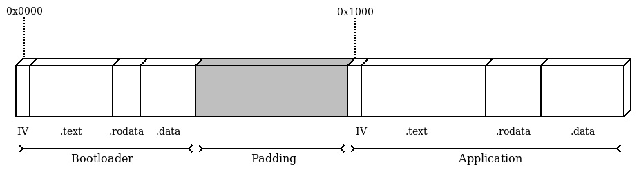
Figure 4.3 – Layout of the flash content, showing the sections of both the bootloader and the application
Bootloader and Application run separate code and can define their own IV based on the handler that will be used in the respective stage. The simplest example of a working bootloader can be realized by hardcoding the address of the application and jumping to the entry point, being the reset handler in the IV of the application stored with offset 4 inside the vector table.
The application may enforce its own memory layout. At startup, it will be able to initialize the new .data and .bss sections according to the new geometry and even define a new initial stack pointer and IV. The bootloader can obtain these two pointers by reading the first two words of the IV stored at address 0x1000:
uint32_t app_end_stack = (*((uint32_t *)(APP_OFFSET)));
void (* app_entry)(void);
app_entry = (void *)(*((uint32_t *)(APP_OFFSET + 4)));
Before jumping to the entry point of the application, we want to reset the main execution stack pointer to the end address of the stack. Since MSP is a special-purpose CPU register in the ARMv7-M architecture, it can only be written using the assembly instruction move special from register (msr). The following code is inlined in the bootloader to set the correct application stack pointer to the value stored in flash at the beginning of the application image:
asm volatile("msr msp, %0" ::"r"(app_end_stack));In Cortex-M3 and other, more powerful, 32-bit Cortex-M CPUs, a control register is present within the system control block area, which can be used to specify an offset for the vector table at runtime. This is the Vector Table Offset Register (VTOR), which is located at address 0xE000ED08. Writing the application offset to this register means that, from that moment, the new IV is in place, and the interrupt handlers defined in the application will be executed upon exceptions:
uint32_t * VTOR = (uint32_t *)0xE000ED08;
*VTOR = (uint32_t *)(APP_OFFSET);
When this mechanism is not available, like in Cortex-M0 microcontrollers, which do not have a VTOR, the application will still share the interrupt vector with the bootloader after it is started. To provide a different set of interrupt handlers, the relevant function pointers can be stored in a different area of the flash, and the bootloader can check whether the application had been started or not at every interrupt, and in case it was, call the respective handler from the table in the application space.
When handling pointers to interrupt handlers and other exception routines, it is important to consider that an exception can occur at any time while running the code, especially if the bootloader has enabled peripherals or activated timers in the CPU. To prevent unpredictable jumps to interrupt routine, it is advisable to disable all the interrupts while the pointers are being updated.
The instruction set provides mechanisms to temporarily mask all the interrupts. While running with the interrupt globally disabled, the execution cannot be interrupted by any exception, excluding NMI. In Cortex-M, interrupts can be temporarily disabled by using the cpsid i assembly statement:
asm volatile ("cpsid i");To enable the interrupt again, the cpsie i instruction is used:
asm volatile ("cpsie i");Running code with interrupts disabled should be done as much as strictly necessary, and not done only in special cases where other solutions are not available because it impacts the latency of the entire system. In this special case, it is used to ensure that no service routines are invoked while the IV is being relocated.
The last action performed by the bootloader in its short life is a direct jump to the reset handler in the application IV. Since the function will never return, and a brand-new stack space has been just allocated, we force an unconditional jump by setting the value CPU program counter register to start executing from the address of app_entry, which is pointed to by isr_reset:
asm volatile("mov pc, %0" :: "r"(app_entry));In our example, this function will never return, since we replaced the execution stack pointer value. This is compatible with the behavior foreseen by the reset handler, which will, in turn, jump to the main function in the application.
Building the image
Since the two executables will be built in separate .elf files, there are mechanisms to join the content of the two partitions together into a single image, to upload to the target, or to use in the emulator. The bootloader partition can be filled with zeros up to its size by using the --pad-to option of objcopy when converting the .elf executable into the binary image. Wearing the flash can be reduced by using the 0xFF value to fill the padding area, which can be obtained by passing the --gap- option fill=0xFF. The resultant image bootloader.bin will be exactly 4096 bytes so that the application image can be concatenated at the end of it. The steps to compose an image containing the two partitions are the following:
$ arm-none-eabi-objcopy -O binary --pad-to=4096 --gap-fill=0xFF bootloader.elf bootloader.bin
$ arm-none-eabi-objcopy -O binary app.elf app.bin
$ cat bootloader.bin app.bin > image.bin
Looking at the resultant image.bin file with a hexadecimal editor, it should be possible to identify the end of the bootloader within the first partition by recognizing the zero pattern that is used by objdump as padding, and the application code starting at address 0x1000.
By aligning the application offset to the start of a physical page in flash instead, it is even possible to upload the two images in separate steps, allowing you, for instance, to upgrade the application code, leaving the bootloader partition untouched.
Debugging a multi-stage system
The separation between two or more stages implies that the symbols of the two executables are linked into different .elf files. Debugging using both sets of symbols is still possible, but the symbols from both .elf files must be loaded in the debugger in two steps. When the debugger is executed using the symbols from the bootloader, by adding the bootloader.elf file as an argument, or using the file command from the GDB command line, the symbols of the bootloader are loaded in the symbol table for the debugging session. To add the symbols from the application .elf file, we can add the corresponding .elf at a later stage using add-symbol-file.
The add-symbol-file directive, unlike file, ensures that the symbols of a second executable are loaded without overwriting the ones previously loaded and allows you to specify the address where the .text section starts. In the system composed in this example, there is no clash between the two sets of symbols, as the two partitions do not share any area on the flash. The debugger can continue the execution normally and still have all the symbols available after the bootloader jumps to the application entry point:
> add-symbol-file app.elf
add symbol table from file "app.elf"(y or n) y
Reading symbols from app.elf...done.
Sharing the same names for sections and symbols between the two executables is legal, as the two executables are self-contained and not linked together. The debugger is aware of duplicate names when we refer to a symbol by its name during debugging. For example, if we place a breakpoint on main and we have correctly loaded the symbols from both executables, the breakpoint will be set on both locations:
> b main
Breakpoint 1 at 0x14e: main. (2 locations)
> info b
Num Type Disp Enb Address What
1 breakpoint keep y <MULTIPLE>
1.1 y 0x0000014e in main at startup_bl.c:53
1.2 y 0x00001158 in main at startup.c:53
Separate boot stages are completely isolated from each other and do not share any executable code. For this reason, software distributed with different licenses, even if not compatible with each other, can run in separate boot stages. As seen in the example, the two software images can use the same symbol names without creating conflicts, as they would have been running on two separate systems.
In some cases, however, multiple boot stages may have functionalities in common that can be implemented using the same library. Unfortunately, there is no simple way to access the symbols of the library from separate software images. The mechanism described in the next example provides access to shared libraries between the two stages by storing the symbols needed only once in the flash.
Shared libraries
Suppose that there is a small library providing general-purpose utilities or device drivers, which is in use by both the bootloader and the application. Even when the footprint is small, it is preferable not to have duplicate definitions of the same functions in the flash memory. The library can instead be linked in a dedicated section of the bootloader and referred to in a later stage. In our preceding two-stage example, we can safely place the API function pointers in an array starting at address 0x400, which is past the end of the interrupt vector we are currently using. In a real project, the offset must be high enough to be after the actual vector table in memory. The .utils input section is placed in the linker script in between the vector table and the start of .text in the bootloader:
.text :
{
  _start_text = .;
  KEEP(*(.isr_vector))
  . = 0x400;
  KEEP(*(.utils))
  *(.text*)
  *(.rodata*)
  . = ALIGN(4);
  _end_text = .;
} > FLASH
The actual function definitions can be placed in a different source file and linked in the bootloader. What is actually in the .utils section is a table containing the pointers to the actual address of the functions inside the .text bootloader output section:
__attribute__((section(".utils"),used))
 static void *utils_interface[4] = {
   (void *)(utils_open),
   (void *)(utils_write),
   (void *)(utils_read),
   (void *)(utils_close)
};
The layout of the bootloader now has this extra .utils section, aligned at address 0x400, containing a table with the pointers to the library functions that are meant to be exported for use from other stages:
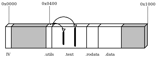
Figure 4.4 – Bootloader partition with the .utils section
The application expects to find the function table at the given address:
static void **utils_interface = (void**)(0x00000400);
The address of the single functions that have been stored in the bootloader is now available, but there is no information about the signature of these functions. For this reason, the application can only access the API properly if the pointers are converted to match the expected function signature. An inline wrapper can then be provided so that the application code can access the function directly:
static inline int utils_read(void *buf, int size) {
  int (*do_read)(void*, int) = (int (*)(void*,int))
    (utils_interface[2]);
  return do_read(buf, size);
}
In this case, the contract is implicitly shared between the two modules, and the correspondence between the function signatures is not checked at compile time, nor is the validity of the function pointer stored in flash. On the other hand, it is a valid approach to avoid binary code duplication and might be an effective way to reduce flash usage by sharing symbols across separate contexts.
Remote firmware updates
One of the reasons to include a bootloader in an embedded system design is often to provide a mechanism to update the running application from a remote location. As mentioned in the previous chapter, a reliable update mechanism is often a critical requirement for vulnerability management. On rich embedded systems running Linux, bootloaders are often equipped with their own TCP/IP stacks, network device drivers, and protocol-specific implementations to transfer kernel and filesystem updates autonomously. On smaller embedded systems, it is often convenient to assign this task to the application, which is in most cases already using similar communication channels for other functional purposes. Once the new firmware has been downloaded and stored in any non-volatile memory support (for example, in a partition at the end of the flash memory), a bootloader could implement a mechanism to install the received update by overwriting the previous firmware in the Application partition.
Secure boot
Many projects require a mechanism to prevent the execution of unauthorized or altered firmware that could have been compromised intentionally by an attacker in an attempt to take control of the system. This is a task for secure bootloaders, which use cryptography to verify the authenticity of a signature calculated on the content of the firmware image on board. Secure bootloaders implementing such mechanisms rely on a trust anchor to store a public key and require the use of a manifest that must be attached to the firmware image file. The manifest contains the signature that has been created by the owner of the private key associated with the public key stored in the device. Cryptographic signature verification is a very effective method to prevent unauthorized firmware updates, both from remote locations and from physical attacks.
Implementing a secure bootloader from scratch is a considerable amount of work. A few open source projects provide a mechanism to sign and verify images using cryptography algorithms. wolfBoot is a secure bootloader providing integrity and authenticity checks of the current firmware and the candidates for update installations. It provides a fail-safe mechanism to swap the two firmware partitions’ content during the update installation, to provide a backup in case of failed execution of the newly updated image. The bootloader comes with tools to generate the signature and attach the manifest to the file to be transferred to the device, and a wide range of configurable options, ciphers, and features.
Summary
Understanding the boot procedure is a key step toward the development of an embedded system. We have seen how to boot straight into the bare-metal application, and we have examined the structures involved in a multi-stage system boot, such as separate linker scripts with different entry points, the relocation of IVs via CPU registers, and shared code sections across stages.
In the next chapter, we will explore mechanisms and approaches for memory management that represent the most important factor to take into account while developing safe and reliable embedded systems.