7
Rotational Stresses
7.1 INTRODUCTION
High centrifugal forces are developed in machine components rotating at a high angular speed of the order of 100 to 500 rps. High centrifugal force produces high hoop and radial stresses in machine components such as rotors and blades of steam and gas turbines. It is almost necessary to analyse these stresses in such components because these are subjected to fatigue loading and creep strain. Many a times a component fails due to crack developed by fatigue and creep during operation. In this chapter we will analyse hoop and radial stresses in components like thin disc, long cylinder, or a disc of uniform strength rotating at high angular speeds.
7.2 ROTATING RING
Consider a ring of mean radius R, rotating about its axis O, with circular speed ω as shown in Figure 7.1. Say the section of the ring is rectangular with breadth b and thickness t as shown in the figure. Take a small element abcd, subtending an angle dθ at the centre, at angular displacement θ from x−x axis.
Volume of small element = Rdθbt
if weight density of ring = ρ
weight of small element = ρRbtdθ
where |
ρ = weight density, |
|
ω = angular velocity in rad/s, and |
|
g = acceleration due to gravity. |
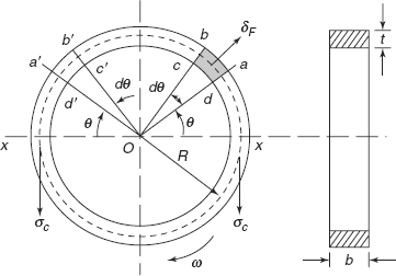
Figure 7.1 Rotating ring
Horizontal component of centrifugal force will be cancelled when we consider another small element a′b′c′d′ in second quadrant at an angle θ, but the vertical component of dF will be added.
Total vertical component or the bursting force on ring in vertical direction acting on horizontal diameter xx:
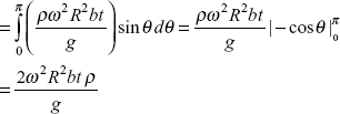
Say, σc is the hoop stress developed in horizontal section along xx.
Area of cross section resisting the force = 2bt
Resisting force ![]()
Circumferential or hoop stress developed in section of ring,
where V = linear velocity of ring at radius R = ωR.
Example 7.1 To develop substantial stress in ring, ω has to be very high.
Let us take a ring of mild steel with weight density of 7.8 gm/cc or 7800 kg/m3 or 76.44 × 10³ N/m3.
Solution: Say the yield point stress of mild steel is 280 N/mm2 and let us take σyp = σc, developed in ring
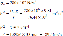
If we take ring radius equal to 0.5 m, then angular speed required to develop hoop stress of the order of 280 N/mm2 is
or 3620 revolutions per minute.
Exercise 7.1 Find the safe number of revolutions per minute for a thin ring of 2 metres in diameter if the stress in the ring is not to exceed 150 N/mm2.
Ans. [1324 rpm].
7.3 STRESSES IN A THIN ROTATING DISC
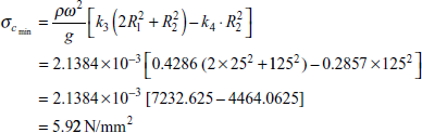
Consider a thin disc of inner radius R1 and outer radius R2, rotating at an angular speed ω about its axis o. The thickness t of the disc is small and it is assumed that stresses in the disc along the thickness do not vary and there is no axial stress developed in the disc; in other words the disc is under plane stress conditions. Take a small element abcd at a radius r, of thickness dr, subtending an angle dθ at the centre of the disc (Figure 7.2).
When the disc is rotating at a high speed, say radius r changes to r + u and the radius r + dr changes to r + u + dr + du. In other words, change in radius r is u and change in radial thickness dr is du. Say circumferential stress developed is σc at radius r.
Radial stress at radius r is σc.
Say ρ = weight density of thin disc.
weight of the small element = ρ(rdθ)tdr.
Centrifugal force on small element,
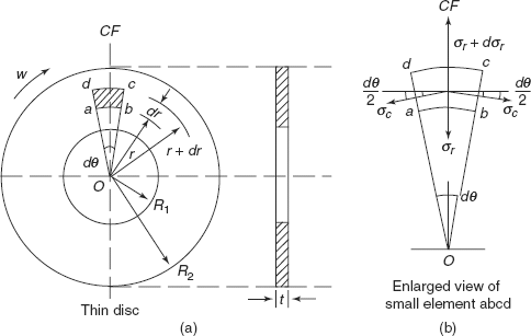
Figure 7.2 Thin rotating disc
Circumferential forces on faces ad and bc = σc dr t.
Radial force on face ab = σrr dθ t.
Radial force on face cd = (σr + dσr)(r + dr) dθ t.
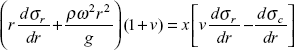
Resolving the forces along the vertical direction oCF as shown is Figure 7.2(b)
But angle dθ → o is very small
Moreover, r dθ is common on both sides; simplifying Eq. (7.1) and neglecting the term dσr dr, we get
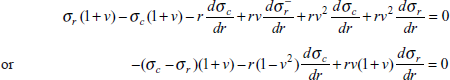
Dividing Eq. (7.2) throughout by dr, we get
or
Now considering the strains in circumferential and radial directions
Circumferential strain,
where E is Young’s modulus and v is Poisson’s ratio.
Radial strains,
or
Differentiating Eq. (7.4) with respect to r, we get
Equating Eqs (7.5) and (7.6), we get
After the simplification of this equation
Putting the value of (σc − σr) from Eq. (7.3) in Eq. (7.8)
Simplifying this equation
or
Integrating Eq. (7.9) we get
where A is constant of integration,
From Eq. (7.3)
Putting this value in Eq. (7.10) we get
or
Multiplying Eq. (7.12) by r throughout, we get
Integrating Eq. (7.13),
where B is another constant of integration
or
Radial stress,
From Eq. (7.10)
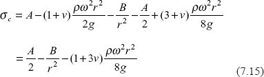
Putting the value of σr, we get
hoop stress
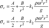
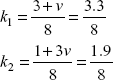
Let us take ![]() constant, and
constant, and ![]() another constant.
another constant.
Expressions for stresses will now be:
Radial stress
Constants A and B can be determined by using boundary conditions of a thin hollow disc:
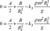
Radial stress σr = 0 at r = R1; and at r = R2
(normal stress on free surfaces is zero), therefore
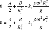
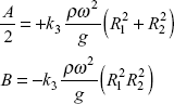
From these two equations, values of constants are
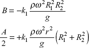
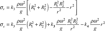
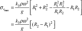
Final expressions for stresses for hollow disc are
where
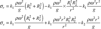
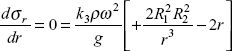
For radial stress to be maximum, ![]()
or
or
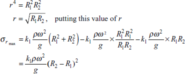
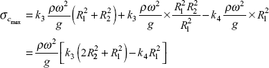
From the expression for σc, reader can find that maximum circumferential stress will occur at r equal to minimum value, i.e. r = R1, (inner radius).
Solid Disc
In a solid disc, at r = 0, i.e. at centre, stresses cannot be infinite, therefore constant B has to be zero otherwise ![]() will become infinite at centre. So, stresses are
will become infinite at centre. So, stresses are
Say outer radius of solid disc = R.
At outer surface, radial stress σr = 0. Therefore
Constant, ![]()
Stresses at any radius r,
obviously both the stresses are maximum at centre, i.e. at r = 0
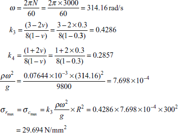
Example 7.2 A thin uniform steel disc of diameter 500 mm is rotating about its axis at 3000 rpm. Calculate the maximum principal stress and maximum in plane shear stress in the disc. Draw the circumferential stress and radial stress distribution along the radius of thin disc.
Given Poisson’s ratio,
Solution: Radius, R = 250 mm
Constants
Maximum principal stress σr, σc at centre
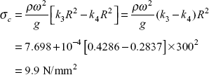
Expression for radial stress
Hoop stress
Distribution of radial and hoop stresses is shown in Figure 7.3. Maximum in plane shear stress occurs at outer radius
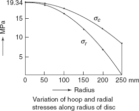
Figure 7.3 Example 7.2
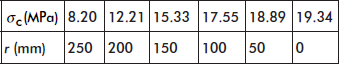
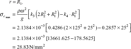
Example 7.3 A thin uniform disc of inner radius 50 mm and outer radius 200 mm is rotating at 6000 rpm about its axis. What are maximum hoop and radial stresses. Draw distribution of hoop and radial stresses along the radius of disc.
Solution:
R1, inner radius = 50 mm
R2, outer radius = 200 mm
Angular speed,
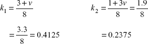
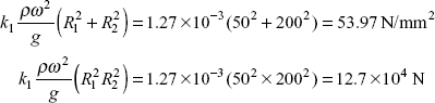
Constants,
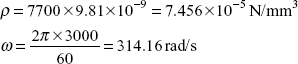
Weight density, ρ = 7800 × 9.81 × 10−9 N/mm3 = 7.65 × 10⁻⁵ N/mm3
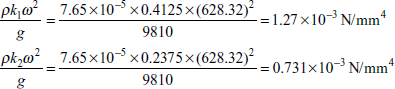
Let us calculate also
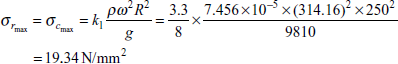
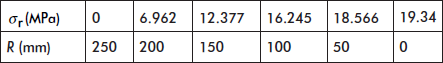
Radial stress
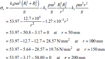
Maxm σr occurs at
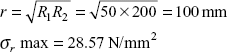
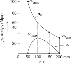
Figure 7.4 Variation of hoop and radial stresses along radious of disc
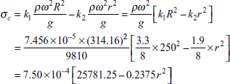
Circumferential Stress
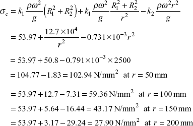
Note that maximum circumferential stress occurs at inner radius and minimum circumferential stress occurs at outer radius as is obvious from Figure 7.4.
Exercise 7.2 A thin uniform steel disc of radius 300 mm is rotating at 3000 rpm about its axis. Draw the radial and circumferential stress distribution along the radius of the disc. What are maximum values of these stresses.
Given ρ=0.078N/cm3, Poisson’s ratio = 0.3, g = 9.81 m/s2.
Ans. [σc max = 29.13 MPa, σc min = 12.36 N/mm2, σr max = 29.13 MPa, σr min = 0].
Exercise 7.3 A thin uniform disc of inner diameter 50 mm and outer diameter 250 mm is rotating at 10,000 rpm. Determine maximum and minimum values of hoop and radial stresses. Draw the stress distribution along radius of disc.
Given ρ = 0.0883N/cm3; v = 0.33, g = 9.81 m/s2.
Ans. [129.2, 30.90 MPa, 0, 41.084, 0 N/mm2].
7.4 DISC OF UNIFORM STRENGTH
Rotors of steam or gas turbines, on the periphery of which blades are attached, are designed as disc of uniform strength, in which the stress developed due to centrifugal forces are equal and constant independent of radius. In order to achieve the objective of uniform strength throughout, thickness of the disc is varied along the radius. Consider a disc of radius R, rotating at angular speed ω about its axis, as shown in Figure 7.5. Take a small element abcd subtending on angle dθ at the centre of disc. Disc is of uniform strength. Stress on faces ab, bc, cd, and da of small element is σ as shown. Thickness of element at radius r is t and say at radius r + dr thickness is t + dt.
Volume of small element = rdθtdr
Mass of the element = ![]()
Centrifugal force on small element,
Radial force on face ab = rdθtσ
Radial force on face cd = (r+dr) dθ(t+dt)σ
Forces on faces bc and da = rdθtσ
where σ is uniform stress.
These forces are inclined at an angle ![]() to horizontal direction as shown.
to horizontal direction as shown.
Resolving all these forces along the radial direction OCF
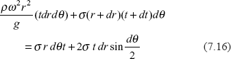
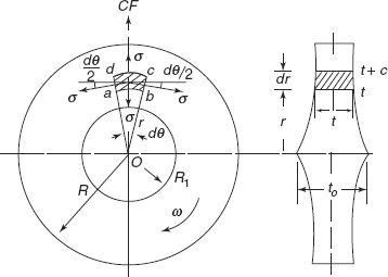
Figure 7.5 Disc of uniform strength
but dθ is very small, so ![]() in all these terms dθ is common, simplifying the equation we can write
in all these terms dθ is common, simplifying the equation we can write
neglecting dr × dt as negligible.
or
or
Integrating Eq. (7.17), we get
where ln A is constant of integration,
|
|
|
|
|
|
At centre, r = 0, thickness t = t0
So, t0 = Ae0 = A
or constant
Equation for thickness becomes
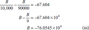
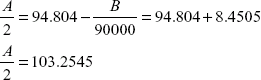
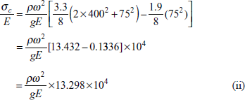
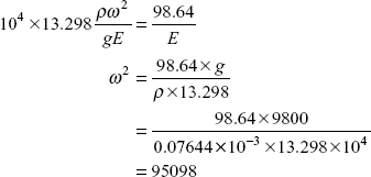
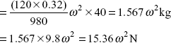
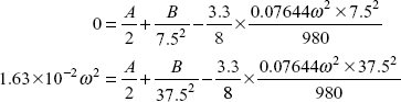
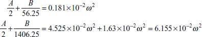
Example 7.4 A steel disc of a turbine is to be designed so that radial and circumferential stresses are to be the same throughout the thickness and radius of disc and is equal to 80 MPa, when running at 3500 rpm. If the axial thickness at the centre is 20 mm, what is the thickness at the radius of 500 mm? ρ for steel = 0.07644N/cm3, g = 9810mm/s.
Solution:
Thickness at centre, |
t0 = 20 mm |
radius |
r = 500 mm |
|
|
Constant strength, |
σ = 80MPa |
density = 0.07644 × 10⁻³N/mm3

Thickness, t = t0 e−1.636 = 20 × 0.1947 = 3.895 mm
Exercise 7.4 A steel rotor of a steam turbine is rotating at 10,000 rpm. At the blade ring its diameter is 600 mm and its axial thickness at centre is 90 mm. Calculate the thickness of rotor at blade ring and at a radius of 150 mm. If it has uniform values of radial and hoop stress equal to 160 N/mm2.ρ = 0.078N/cm3 g =9.81 m/s2
Ans. [7.75 mm; 48.75 mm].
7.5 STRESSES IN ROTATING LONG CYLINDERS
The analysis of stresses in long cylinders is similar to that of a thin disc. The only difference is that length of the cylinder along the axis of rotation is large as compared to its radius and axial stress is also taken into account, i.e. at any radius r of the cylinder there are three stresses, i.e. σa, axial stress; σr radial stress, and σc the circumferential stress. While developing the theory for long rotating cylinders following assumptions are taken:
- Transverse sections of the cylinder remain plane at high speeds of rotation. This is true only for sections away from the ends.
- At the central cross section of the cylinder, shear stress is zero due to symmetry and there are three principal stresses, i.e. σr, σa, and σc as stated above.
If E is the Young’s modulus and v is the Poisson’s ratio, then
Hoop strain,
Radial strain,
Axial strains,
In article 7.3, we have derived expression for (σc − σr) for a small element subtending an angle dθ at the centre of disc, the equations of equilibrium give
But circumferential strain,
Radial strain,
Differentiating Eq. (7.19) with respect to r, we get
Equating Eqs (7.20) and (7.21) and after simplification, we get
As per the first assumption, the transverse sections remain plane after the long cylinder starts rotating at high angular speeds; it is implied that the axial strain is constant, therefore
In this E and v are elastic constants, therefore
Differentiating Eq. (7.23) with respect to r, we get
or
Substituting the value of ![]() in Eq. (7.22), we get
in Eq. (7.22), we get
After further simplification
But from Eq. (7.18), we get
Substituting this value of (σc − σr) in Eq. (7.24)

or
Integrating Eq. (7.25), we get
where A is constant of integration.
But
From Eqs (7.26) and (7.18), we get
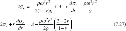
Multiplying throughout by r, we get
Integrating Eq. (7.28), we get
where B is another constant of integration.
Or radial stress,
But from Eq. (7.26) ![]()
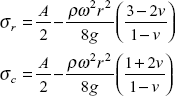
From Eqs (7.26) and (7.29), we get the value of σc
or hoop stress,
Solid cylinder
In the case of solid long cylinder, stress at the centre cannot be infinite; therefore constant B = 0, expression for stresses will be
At the outer free surface, radial stress σr has to be zero, so
at |
r = R, outerradius |
|
σr = 0, |
|
|
|
|
Expression for stresses will now be
If we put constant
Stresses will be
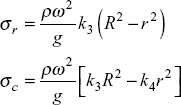
σr and σc are maximum at the centre of the cylinder
Hollow cylinder
Stresses in a hollow cylinder are
|
|
|
|
But radial stress is zero at inner and outer free surfaces of cylinder, i.e.
So,
From these equations
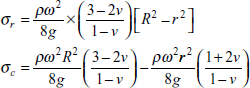
Finally the expressions for stresses are
Obviously σc will be maximum when r is minimum, i.e. at inner radius, R1
To obtain the value of σr max, let us put
or

Putting this value of r in expression for σr
Example 7.5 A solid long cylinder of diameter 600 mm is rotating at 3000 rpm. Calculate (i) maximum and minimum hoop stresses and (ii) maximum radial stress.
Given ρ = 0.07644 N/cm3, g = 9.8 m/s2, v = 0.3
Solution: Radius, |
R = 300 mm |
|
ρ = .07644 × 10−3 N/mm3 |
|
g = 9800 mm/s2, v = 0.3 |
Minimum hoop stress occurs at outer radius
Example 7.6 A long cylinder of inside diameter 50 mm and outside diameter 250 mm is rotating at 5000 rpm, calculate (i) minimum and maximum hoop stresses and (ii) maximum radial stress and at what radius it occurs?
Given ρ = 0.07644 ×−3/mm3, v = 0.3, g = 9.8 m/s2
Solution: |
Inner radius, R1 = 25 mm |
|
Outer radius, R2 = 125 mm. |
Constants
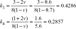
Angular speed,
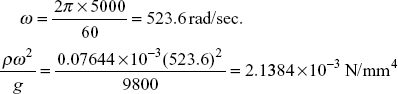
![]() occurs at
occurs at
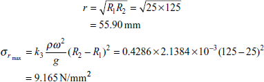
Circumferential stress,
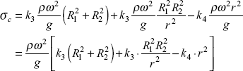
At inner radius,
At outer radius, ![]() at r = R2
at r = R2
Exercise 7.5 A solid long cylinder of diameter 400 mm is rotating about its axis at an angular speed of 300 rad /s. Draw the radial and circumferential stress distribution along its radius. Determine the maximum and minimum values of radial and hoop stresses.
Given ρ = 0.07644 × 10 3 N/mm3, v =0.3, g = 9.81m/s2
Ans. [12.035N/mm2, 0,12.037N/mm2; 4.012N/mm2].
Exercise 7.6 A long cylinder of steel of outer diameter 750 mm and inner diameter 250 mm is rotating about its axis at 4000 rpm. Draw the radial stress and circumferential stress distribution along the radius of cylinder.
Given ρ = 0.078 N/cm3, v = 0.3, g = 980 m/s2
Ans. [171.5, 46.784 N/mm2, maximum and min. circumferential stress, σr = 0 at inner and outer radii, ![]() at radius of 216.5 mm].
at radius of 216.5 mm].
7.6 TEMPERATURE STRESSES IN A THIN DISC
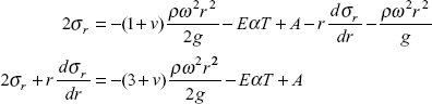
Consider a thin disc rotating at a high angular speed ω and subjected to temperature variation, at the same time as shown in Figure 7.6. Say the stresses are σc, circumferential, and σr, radial, and α is the coefficient of thermal expansion of the material, T is the change in temperature. Consider a small element abcd subtending an angle dθ at centre, radial thickness dr. At high speed
Circumferential strain,
Radial strain,
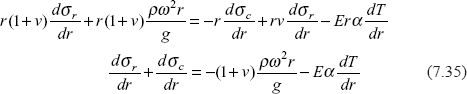
Following equation is already derived in article 6.3.
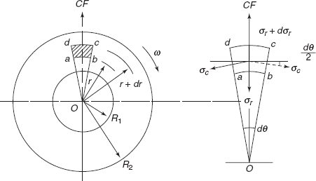
Figure 7.6 Rotating thin disc
From Eq. (7.31)
Equating Eqs (7.32) and (7.34)
or
Putting the value of (σc – σr) from Eq. (7.33)
Integrating Eq. (7.35)
where A is constant of integration.
From Eqs (7.33) and (7.36), eliminating σc
Multiplying throughout by r
Integrating Eq. (7.37), we get
where B is another constant of integration.
Radial stress,
putting the value of σr in Eq. (7.36), we get
Constants A and B can be determined by using boundary conditions. For a solid disc, constant B = 0, because stress cannot be infinite at the centre of the disc.
Example 7.7 A thin disc of outer radius 300 mm and inner radius 100 mm is rotating about its axis at 3500 rpm. Temperature in the disc has a linear variation of temperature with temperature 80°C at outer radius and 24°C at inner radius, calculate the maximum stress.
|
E = 208 kN/mm2, ρ = 0.07644 N/cm3; v = 0.3, g = 9.80 m/s2 |
Given |
α = 11 × 10–6/°C |
Solution: Angular speed,
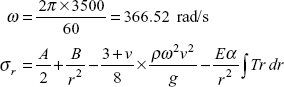
Temperature variation
Radial stress, σr = 0 at r = 100 mm, r = 300 mn
Taking temperature 20°C, constant from centre to inner radius of disc
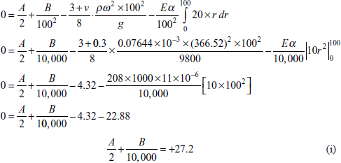
Putting second boundary condition,
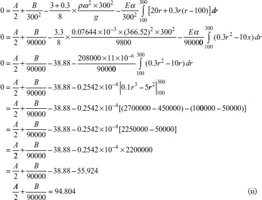
Maxm stress occurs at the inner radius r = 100 mm, at r = 100 mm.
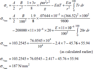
maximum strees i.e. circumferential stress occurs at inner radus.
Exercise 7.7 A thin uniform steel disc of diameter 500 mm is rotating about its axis at 5000 rpm. Determine the stresses developed at the centre of the disc and at its periphery if the disc has a linear variation of temperature of 50°C between the centre and in outer edge. (Temperature varies from zero at centre to 50°C at periphery.) Given α = 11 × 10–6/°C, ρ = 0.07644 × 10⁻³ N/mm3, g = 9800 mm/s2 E = 210 GPa, v = 0.3
Ans. [At the centre of the disc ![]() = 93.8 N/mm2, at the periphery σc = –15.04 N/mm2].
= 93.8 N/mm2, at the periphery σc = –15.04 N/mm2].
Problem 7.1 A composite ring is made by fitting a steel ring over a copper ring as shown in Figure 7.7. Diameter of the ring at common surface is 1.6 m. Radial thickness of both the rings is 20 mm and axial width of both rings is 30 mm. Determine the hoop stresses set up in steel and copper rings if the composite ring is rotating at 1200 rpm.
For steel |
E = 210 GPa, |
|
ρs = 0.07644 × 10⁻³ N/mm3 |
For copper |
E = 105 GPa, |
|
ρc = 0.08584 × 10⁻³ N/mm3 |
|
g = 9810 mm/s2 |
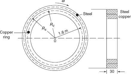
Figure 7.7 Composite ring
Solution:
Radius at common surface = 80 cm = 800 mm
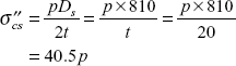
Radial thickness of each ring = 20 mm
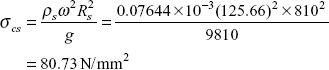
Rs, mean radius of steel ring = 800 + 10 = 810 mm
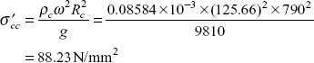
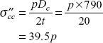
Rc, mean radius of copper ring = 800 – 10 = 790 mm
Angular speed, ![]()
Hoop stress in steel ring,
Hoop stress in copper ring,
Hoop stress developed in copper ring is more than the hoop stress developed in steel ring (due to more centrifugal force acting on copper ring), copper ring exerts radial pressure on steel ring. Say this radial pressure is p N/mm2. This will produce tensile hoop stress in steel ring but compressive hoop stress in copper ring.
Tensile hoop stress in steel ring,
Compressive hoop stress in copper ring,
Resultant hoop stress in steel ring
Resultant hoop stress in copper ring,
Strain compatibility
Since both the rings are rotating together, circumferential strain in steel ring will be the same as the circumferential strain in copper ring (neglecting the effect of lateral strain due to junction pressure p)
But Es = 2Ec
So,
|
80.73 + 40.5p |
= |
2(86.23 − 39.5p) |
|
119.5 p |
= |
91.73 |
|
p |
= |
0.7676 N/mm2 |
So,
σcs |
= |
80.73 + 40.5 × 0.7676 = 80.73 + 31.09 = 111.82N/mm2 |
σcc |
= |
86.23 − 39.5 × 0.7676 = 80.23 − 30.32 = 55.91N/mm2 |
Resultant hoop stress in steel ring is 111.82 N/mm2 and in resultant hoop stress in copper ring is 55.91 N/mm2.
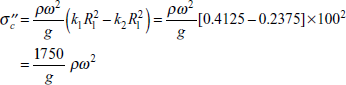
Problem 7.2 Determine the stresses due to the centrifugal force in a rotor with an outer radius 500 mm and radius of the hole 100 mm. The outer portion of the rotor is cut by slots 200 mm deep for windings (as shown in Figure 7.8). The rotor is of steel and rotates at 3000 rpm. The weight of the windings in the slots is the same as that of the material removed.
ρ for steel = 0.076 N/cm3
Poisson’s ratio = 0.3 and g = 9.81 m/s2
Solution: Because the slots are cut in the outer portion of the rotor, the part of the rotor between the radii 30 to 50 cm can support no tensile hoop stress. The centrifugal force due to this rotating ring of 30 to 50 cm radius produces a tensile radial stress across the surface of the disc of 30 cm radius.
Say the radial stress at radius 30 cm = p0
Say thickness of the rotor = t cm.
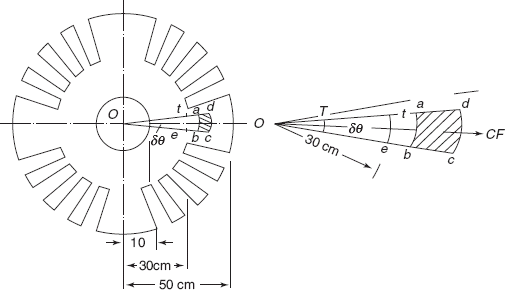
Figure 7.8 Rotor with slots
Consider a small element abcd subtending an angle δθ at the centre, at a radius r with radial thickness δr,
Centrifugal force on this small element
Area of the section at radius 30 cm
Stress
So,
Now on a disc of outer radius 30 cm and inner radius 10 cm, a radial pressure p0 tensile is acting. Due to this p0, the hoop stress (or the circumferential stress) developed at radius 30 cm is
(refer to the formula on thick cylinders).
Considering whole of the rotor as a hollow disc, let us find the circumferential stress at the radius of 30 cm,
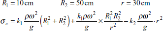
where

σc at r = 30 cm

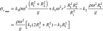
Total maximum circumferential stress at the inner edge of the slot
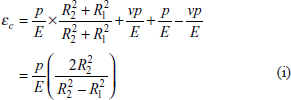
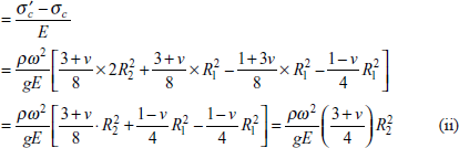
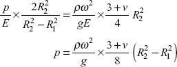
Problem 7.3 A thin circular disc of external radius R2 is forced onto a rigid shaft of radius R1. Prove that when the angular speed is ω, the pressure between the disc and the shaft will be reduced by
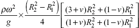
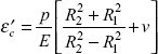
Solution: The thin disc is forced onto the solid shaft, say the initial pressure between the shaft and the disc at the common radius R1 is p. Due to radial pressure p, there will be initial hoop stress in the disc and at the inner radius R1,
Hoop stress,
![]() circumferential strain in the disc at the inner radius
circumferential strain in the disc at the inner radius
because p is compressive and ![]() is tensile when the disc and the shaft are rotating at ω rad/s. Say the radial pressure between the disc and shaft is p’.
is tensile when the disc and the shaft are rotating at ω rad/s. Say the radial pressure between the disc and shaft is p’.
At the inner radius of the disc
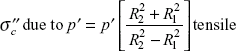
circumferential stress due to rotation.
where
Therefore
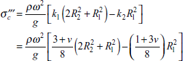
Resultant stress
Hoop strain

Equating the strains ![]() we get
we get
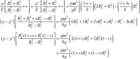
or
Reduction in pressure.
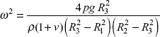
Problem 7.4 If a disc of inside and outside radii R1 and R2 is made up in two parts which are shrunk together, the common radius being R3, show that the hoop stresses at R1 and R2 will be equal at a rotational speed given by
Solution: A disc made up in two parts inner disc (with radii R1 and R3) and outer disc (with radii R3 and R2) is shown in Figure 7.9, p is the junction pressure. Due to the junction pressure, there will be compressive hoop stress developed in inner disc and tensile hoop stress developed in the outer disc.
Stresses due to junction pressure
Inner disc at radius R1,
Outer disc at radius R2,
Stresses due to rotation
The expression for the hoop stress is
where
and
At the inner radius R1
At the outer radius R2
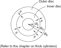
Figure 7.9 Composite disc
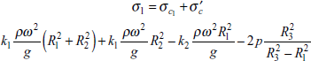
Resultant stresses
At the inner radius,
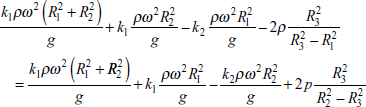
At the outer radius, R2

But as per the condition given
or
or

Problem 7.5 A thin hollow disc of outer radius R2 is shrunk over another solid disc of the same thickness but radius R1, such that the junction pressure between the two is p. Show that in order that the outer disc may not be loosened over the inner disc at the angular speed ω, the minimum value of p should be
where v = Poisson’s ratio and ρ = weight density.
Solution: When the outer disc is loosened over the inner disc, the radial pressure between the two becomes zero.
Initial hoop strain due to junction pressure at inner radius R1
Hoop stress in the outer disc = ![]() tensile
tensile
Hoop strain in the outer disc = ![]() , since p is compressive.
, since p is compressive.
Hoop stress in the inner disc = p (compressive), because inner disc is solid.
Hoop strain in the inner disc = ![]()
Total hoop strain,
Hoop strain due to rotation at R1
Hoop stress in the inner disc at R1
Hoop stress in the outer disc at R1
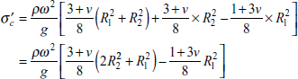
Net hoop strain
Problem 7.6 A thin steel disc of 800 mm diameter is shrunk over a steel shaft of 150 mm diameter such that the shrinkage pressure at the common surface is 50 N/mm2.
At what speed will the disc be loosened on the shaft? Neglect the change in the dimensions of the shaft.
Given ρ = 0.07644 N/cm2, E = 200 GPa, v = 0.3, g = 9800 mm/sec2
Solution: Junction pressure, p = 150 N/mm2
For the disc R1 = 75 mm and R2 = 400 mm.
Hoop stress due to shrinkage at the common surface of the disc
Shrinkage strain
Hoop stress in the disc at the inner radius
because
At the time when the disc loosens on the shaft σr = 0 in the disc. Therefore hoop strain in the disc
Due to rotation when the disc is loosened on the shaft the shrinkage hoop strain becomes zero, therefore
Angular speed, |
ω = 308.38 rad/s |
|
|
Problem 7.7 A thin steel disc 800 mm in diameter is shrunk on a steel shaft of 200 mm diameter. The shrinkage allowance is ![]() of the radius at the common surface.
of the radius at the common surface.
- At what speed the disc will be loosened?
- What are the maximum stresses in the shaft and the disc when stationary?
Given ρ = 0.07644 × 10⁻³ N/mm3, v = 0.3, E = 200 GPa, g = 9.8 m/s2
Solution:
Common radius, |
R1 = 100 mm |
Outer radius, |
R2 = 400 mm |
Shrinkage allowance ![]()
Say Shrinkage pressure = p N/mm2
Hoop stress in disc at
Hoop stress in shaft = –p (compressive)
Hoop strain in disc,
Strain in shaft, ![]() (note that shaft is solid)
(note that shaft is solid)
Total hoop strain ![]()
So,
Junction pressure,
Maximum stress in the disc ![]()
Maximum stress in shaft = –p = –46.88 N/mm2
These are the stresses when the shaft and disc are stationary, due to shrinkage pressure. Say at angular speed w, the disc will be loosened on the shaft, i.e. at this speed, total strain of the disc at the common radius will be equal to the shrinkage strain provided. As a result, the radial stress between the disc and shaft will become zero.
Rotational stress at R1
In the disc,
strain ![]()
in the shaft,
stress,
strain, ![]()
Net hoop strain ![]()
But the strain provided ![]()
So,

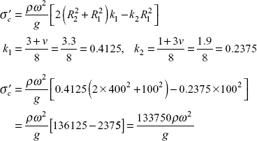
Problem 7.8 A rotor disc of a steam turbine has inside diameter 15 cm and outside diameter 75 cm and axial width of 4 cm. On its periphery blades are fixed at an angular pitch of 3°. The weight of each blade is 0.32 kg with effective radius of 40 cm. Determine the maximum rotational speed as per the maximum principal stress theory of failure.
Yield strength = 270 MPa
ρ = 0.07644 N/cm3
g = 980 cm/sec2, v = 0.3
Solution: Angular pitch of blades = 3°.
Number of blades ![]()
Weight of each blade = 0.32 kg
Total weight = 0.32 × 120
Effective radius r = 40 cm
Say the rotational speed = ω rad/s
Centrifugal force on the periphery due to blades
Resisting area = π × 75 × 4 = 942.48 cm2
Radial stress at the periphery of the disc
Radial stress at the inner radius, 7.5 cm = 0.
Now radial stress ![]()
Using the boundary conditions
From these equations
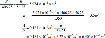
Maximum stress occurs at the inner radius, r = 7.5 cm

So,

MULTIPLE CHOICE QUESTIONS
- A thin rim is rotating about its axis. The linear velocity at the periphery is 10 m/s. If the density of the material is 0.08 × 10⁻³ N/mm3, the maximum stress developed in the rim (if g = 9.8 m/s2) is
- 1.0 N/mm2
- 0.816 N/mm2
- 0.781 N/mm2
- None of these
- A thin hollow disc of inner radius 40 mm and outer radius 160 mm is rotating at a high speed ω rad/s. The maximum radial stress in disc occurs at the radius of
- 40 mm
- 80 mm
- 120 mm
- None of these
- A thin solid disc of radius 50 cm is rotating at N rpm. If the maximum hoop stress developed at inner radius of the disc is 100 MPa, what is the magnitude of maximum radial stress?
- 100 MPa
- 50 MPa
- 25 MPa
- None of these
- A long cylinder of inner radius R1 and outer radius R2 is rotating at angular speed ω rad/s. If r is the weight density of the material of the disc, g = acceleration due to gravity, v = Poisson’s ratio, expression for maximum radial pressure is
- None of these
- A thin hollow circular disc is rotating at a high angular speed. Due to the centrifugal force, radial and hoop stresses are developed in the disc. What is the nature of graph of variation of radial stress along radius of disc?
- Linear
- hyperbolic
- parabolic
- None of these
- A thin circular disc of radius 500 mm is rotating about its centre with a high angular speed. At what radius circumferential and radial stresses developed in disc are equal
- 0.0
- 100 mm
- 70.7 mm
- None of these
- A solid thin disc is rotating about it axis at an angular speed ω rad/s. If the expression
 and radius of disc is 500 mm, what is the radial stress at the outer periphery of the disc?
- 200 N/mm2
- 84 N/mm2
- 50 N/mm2
- None of these
- A thin disc of inner radius 50 mm and outer radius 250 mm is shrunk on a solid shaft of diameter 100 mm. If the junction pressure between the disc and the shaft is 60 N/mm2, what is the maximum hoop stress developed in disc due to junction pressure?
- 65 N/mm2
- 60 N/mm2
- 50 N/mm2
- None of these
- A thin disc of inner radius 50 mm and outer radius 250 mm is shrunk on a solid shaft of diameter 100 mm. If the junction pressure between the disc and the shaft is 60 MPa, then hoop stress developed at the periphery of the disc is
- 5 MPa
- 6 MPa
- 7.5 MPa
- None of these
- A thin disc of inner radius R1 and outer radius R2 is rotating at 1000 RPM. The maximum hoop stress developed in thin disc is 70 MPa. If the yield strength of the material is 280 MPa, at what speed the disc will fail according to the maximum principal stress theory of failure?
- 1000 RPM
- 1414 RPM
- 2000 RPM
- None of these
Answers
1. (b) |
2. (b) |
3. (a) |
4. (b) |
5. (c) |
6. (a) |
7. (d) |
8. (a) |
9. (a) |
10. (c). |
7.1 A uniform slender rod of length L and cross sectional area A is rotating in a horizontal plane about a vertical axis passing through one end. If the unit weight of rod is ρ and it is rotating at constant angular speed ω rad/s, show that the total elongation of the rod is ρω2L3 / 3gl, where g is the acceleration due to gravity and E is the Young’s modulus.
7.2 Calculate the stress in the rim of a pulley when linear velocity of rim is 80 m/s. What will be the stress if the speed is increased by 20%, if mass density = 7800 kg/m3, g, acceleration due to gravity is 9.81 m/s2.
Ans. [49.92 MPa, 71.9 MPa].
7.3 A thin disc of outer radius 300 mm and inner radius 100 mm is rotating about its axis at 3500 rpm. The disc has a linear variation of temperature of 60°C between the inner and outer (hotter) edge. Calculate the maximum hoop stress developed in disc.
Given E = 208 kN/mm2, ρ = 0.07644N/cm3, v = 0.3, g = 9.8m/s2, α = 11 × 10−6 /°C
Ans. [159.63 N/mm2].
7.4 A circular saw 3 mm thick × 600 mm diameter is secured upon a shaft of 80 mm diameter. Material of the saw has a density of 0.078 N/cm3 and Poisson’s ratio is 0.3. Determine the permissible speed if the allowable hoop stress is 120 MPa. Determine the maximum radial stress in saw.
g = 9.81 m/s2
Ans. [4294 RPM; 46.9 MPa at r = 109.54 mm].
7.5 A steel rotor of a turbine is to be designed so that the radial and circumferential stresses are constant throughout and equal to 120 N/mm2, between the radii of 300 mm and 500 mm, when running at 500 rpm; if the axial thickness at outer radius of this zone is 20 mm, what is the thickness at inner radius.
ρ for stress = 0.07742 N/cm3, g = 9.80 m/s
Ans. [85.2 mm].
7.6 Determine the stresses due to the centrifugal force in a rotor with an outer radius of 650 mm and radius of the hole 100 mm. The outer portion of the rotor is cut by slots 250 mm deep for windings. The rotor of steel rotates at 1800 rpm. The weight of the windings in the slots is the same as that of the material removed.
ρ = 0.078 N/cm3, g = 9.81 m/s2, v = 0
Ans. [148.53 N/mm2].
7.7 A thin circular disc of external radius 300 mm is forced on to a rigid shaft of radius 100 mm such that the radial pressure at the junction of the two is 50 N/mm2. The assembly rotates at 300 rad/s. What is the final junction pressure between the two?
ρ = 0.07844 N/cm3, g = 9.81 m/s2, v = 0.3
Ans. [26.834 N/mm2].
7.8 A disc of inside and outside diameters 200 and 500 mm is made up in two parts which are shrunk together. The common diameter being 350 mm. The junction pressure at the common surface is 40 N/mm2. At what speed the hoop stress at the inner and outer radii of the disc will be equal?
g = 9.81 m/s2, ρ = 0.07644 N/cm3, v = 0.29.
Ans. [4095 rpm].
7.9 A thin hollow steel disc of outer radius 500 mm is shrunk over another solid disc of the same thickness and radius 100 mm, such that shrinkage pressure at the common surface is 100 N/mm3. At what speed will the disc be loosened on the shaft? Neglect the strain in the shaft.
ρ = 0.07644 N/cm3, E = 2 × 10⁵ N/mm2, g = 9.80 m/s2, v = 0.3.
Ans. [2788 rpm].
7.10 A thin hollow steel disc of outer radius 500 mm is shrunk on another solid disc of the same thickness but radius 100 mm, such that the junction pressure between the two is p. What should be the minimum value of junction pressure p so that the outer disc may not be loosened over the inner disc at an angular speed of 2500 rpm?
ρ = .078 N/cm3, v = 0.3, g = 9.8 m/s2.
Ans. [78.8 N/mm2].
7.11 A steel rotor disc of a steam turbine has a uniform thickness of 50 mm. The outer diameter of the disc is 600 mm and inner diameter is 100 mm. There are 10 blades each of weight 0.3 kg fixed evenly around, the periphery of the disc at an effective radius of 350 mm. Yield strength of the material is 300 MPa, ρ = 0.07644 N/cm3. Determine the maximum rotational speed as per the maximum shear stress theory of failure.
Ans. [5645 rpm].