
![]()
Managing and Optimizing a Complex RAC Environment
by Syed Jaffar Hussain and Tariq Farooq
Managing any Real Application Cluster (RAC) environment, whether on a small or large scale, comes with its fair share of risks and challenges. At a certain point, balancing out the various components and layers involved in setting up a well-oiled, well-tuned Oracle RAC cluster becomes an art involving a lot of skill and a high level of expertise. This chapter gives you a first-hand shot at tackling some of the problems head-on in an effective and practical manner. There may be some overlap between this chapter and other chapters within certain knowledge streams; this is intentional, as some topics have been re-summarized within this chapter to cover the context of the subject at hand.
The overall goal of this chapter is to present you with ideas, tips, tricks, and methodologies available to manage and optimize large-scale cluster environments for cost-effectiveness, better performance, and easy-to-set-up management. It is essential that you carefully study the pros and cons of every point mentioned in this chapter before you decide to apply any changes into your existing environment.
The following topics have been presented in this chapter to optimize any large-scale cluster environments:
- Comparing the pros and cons of shared vs. non-shared Oracle Homes
- Server pools: Concepts and how to best put them to use
- Planning and designing RAC databases for large-scale environments
- Pros and cons of small- and large-scale cluster environments
- Split-brain scenarios and how to avoid them
- Understanding, debugging, and avoiding node evictions
- Extended distance (stretch) clusters: Synopsis, overview, and best practices
- RAC setup and configuration: Considerations and tips for various OS families
- Oracle Universal Installer (OUI): Setup and configuration—Learning the new way of things
- A quick n’ easy approach to RAC Database tuning
Shared vs. Non-Shared Oracle Homes
In a typical cluster deployment, small, medium, or large sized, each node must at least consist of a Grid Infrastructure (GI) and RDBMS home, where the Oracle Clusterware, Automatic Storage Management (ASM), and RDBMS software binaries will be installed. Though the storage requirement for an individual home is between 8 GB and 4 GB, it is best advised to have at minimum a 100-GB file system under which the homes will be deployed to sustain future requirements, such as upgrades and patching, and also to maintain an adequate free space for various cluster and database logs.
When you have a complex cluster environment with a large number of nodes, let’s say 20 or more nodes, and if the Oracle Homes on each node are configured locally on a local file system, you not only require a large amount of space to house them—say 2 TB for 20 nodes—managing the environment becomes not only complex but also expensive from a storage cost factor perspective.
The administrative complexity and cost can be cut down by sharing the Oracle Homes across nodes in a cluster. Oracle gives the flexibility to have the software installed once in a shared cluster file system, so that it is shared among all other nodes in a RAC cluster. The key advantage of this approach is not only to reduce the overall installation duration of remote copy operation, but also to drastically reduces the storage requirements for other nodes. You can use any Oracle-certified or -supported shared storage to install the Oracle Homes.
During a fresh cluster installation, when a shared storage location is specified to install the software, OUI automatically detects and adjusts to the environment and bypasses the remote node software copy option, speeding up the installation. In addition, this kind of setup requires less storage for the software installation and potentially reduces the duration when you plan to deploy a patch on the existing environment or plann to upgrade the environment. Adding additional nodes also becomes faster when shared Oracle Homes are in place.
The out-of-place upgrade option introduced recently in 11gR2 (11.2.0.2) won’t really hamper the current Oracle Homes much, as it doesn’t require a prolonged downtime during the course of the upgrade. Whereas, the patch deployment in a shared home requires a complete cluster-wide downtime in contrast to non-shared Oracle Homes.
Regardless of shared or non-shared Oracle Homes, both settings have their share of strengths and weaknesses. The following highlights some pros and cons of shared Oracle Homes:
- Less storage requirement
- Oracle Homes backup becomes faster and takes less storage, as it is just a single copy
- Add node (cloning homes) process takes considerably less time
- Patching, upgrade process will become quicker
- All cluster and database logs across nodes can be put under one roof
- Patch consistency will be guaranteed across nodes
- Cluster-wide downtime for patching and upgrade
- Rolling upgrades and patching is not possible
- High-level risk of single point of failure
- If the nodes’ OS are incompatible, will result in cluster instability
Above all, you can also configure a mixed environment: both shared and non-shared Oracle Homes in a single environment. When you have such mixed environment, on selected nodes you can implement shared Oracle Homes to take advantage of storage and other benefits talked about a little earlier. The following configuration is possible in a single environment:
- A non-shared Grid home among all the nodes
- A shared ORACLE RDBMS HOME among all the nodes
- A shared ORACLE RDBMS HOME for a group of nodes and a non-shared ORACLE RDBMS HOME for the rest of the nodes
Figure 7-1 depicts non-shared, shared, and mixed OH env settings.

Figure 7-1. Shared/non-shared/mixed OH environment
A new feature introduced with 11gR2, server pools, is a dynamic grouping of Oracle RAC instances into abstracted RAC pools, by virtue of which a RAC cluster can be efficiently and effectively partitioned, managed, and optimized. Simply put, they are a logical grouping of server resources in a RAC cluster and enable the automatic on-demand startup and shutdown of RAC instances on various nodes of a RAC cluster.
Server pools generally translate into a hard decoupling of resources within a RAC cluster. Databases must be policy managed, as opposed to admin managed (the older way of RAC server partitioning: pre-11gR2) for them to be organized as/within server pools.
Each cluster-managed database service has a one-to-one relationship with server pools; a DB service cannot be a constituent of multiple server pools at the same time.
server pools and policy management of RAC database instances come in real handy when you have large RAC clusters with a lot of nodes present. However, this technology can be used for policy-based management of smaller clusters as well.
Types of Server Pools
Server pools are classified into two types, both of which are explained in detail as follows:
- System-defined server pools
- User-defined server pools
As the name implies, these server pools are created by default automatically with a new installation. Server pools of this type house any/all non-policy-managed databases. System-defined server pools are further broken up into two subcategories:
- GENERIC server pool
In addition to RAC servers assigned to a system-defined server pool, all non-policy-managed (admin-managed) databases are housed within the GENERIC server pool. The attributes of a GENERIC server pool are not modifiable.
- FREE server pool
All unassigned RAC servers automatically get attached to the FREE server pool by default. Common attributes of a server pool (MIN_SIZE, MAX_SIZE, SERVER_NAMES) are not modifiable within the FREE server pool. However, the IMPORTANCE and ACL properties of the FREE server pool can be changed.
The attributes of user-defined server pools are listed as follows. This methodology is termed “server categorization” by Oracle.
- NAME: Define the name of the server pool with this attribute
- IMPORTANCE: Comparative importance of server pool. Values allowed in order of importance: 0-1,000
- MIN_SIZE: Minimum no. of nodes within a server pool. Default value is 0
- MAX_SIZE: Maximum no. of nodes within a server pool. A value of -1 defines a cluster-wide server pool
- ACL: Access Control List containing security/users/privileges information about the server pool
- SERVER_CATEGORY: Defines server category; this is an attribute mutually exclusive to the SERVER_NAMES attribute; only one can be set at a time (not both)
- SERVER_NAMES: A hard coupling of RAC servers to the server pool. This is an attribute mutually exclusive to the SERVER_CATEGORY attribute; only one can be set at a time (not both)
- ACTIVE_SERVERS: This is an auto-managed attribute and changes in real time
- SERVERPOOL: Name of the server pool
- EXCLUSIVE_POOLS: Defines whether the RAC servers are shareable among server pools or not
- PARENT_POOLS: Specifies if a server pool is a child of another pool (nested pools)
Creating and Managing Server Pools
Server pools (with RAC servers attached to them) can easily be defined at database creation time within the Database Configuration Assistant (DBCA) as well as with the SRVCTL and CRSCTL command-line utilities. Additionally, they can be created/managed from Oracle Enterprise Manager (recommended approach).
Some examples of command-line and GUI tool options for adding and managing server pools are listed as follows.
$ crsctl add serverpool bsfsrvpool0l -attr MIN_SIZE=1, MAX_SIZE=2, IMPORTANCE=100
$ crsctl delete serverpool
$ crsctl status serverpool -f
$ srvctl config serverpool


Figures 7-3. Examples: Creating/attaching to a server pool using DBCA


Figures 7-6. Creating and managing server pools within Oracle Enterprise Manager Cloud Control
Planning and Designing RAC Databases
Before a new RAC database is deployed in a complex/large-scale cluster environment, it is essential that you carefully plan and design the database resources keeping in view the requirements from the application and business points of view. When you plan a new database, you have to consider the core requirements of the application and future business demands, such as increased workload, how to control the resources on the server, etc. When multiple databases are configured on a node, each database has a different requirement for CPU and memory resources. Some databases need more resources, while others need much less. However, there will be no control over the CPU consumption by default to the instances running on the node.
In the subsequent sections, we give you some valuable tips to optimize RAC databases by introducing some of the new features introduced in the recent and current Oracle versions, for example, instance caging and policy-managed database.
From 11gR2 onward, you will be given a choice to create two alternative types of RAC database management configuration options during database creation within DBCA: admin managed and policy managed. Depending on the application and business needs and considering the business workload demands, you can choose the configuration option to create either an admin-managed or a policy-managed database. The typical admin-managed databases are sort of static and assign to a specific set of nodes in the cluster, their connect configuration as well. You will define your requirements during the course of database or its service creation, which is pinned to particular nodes on which they will be deployed and reside in. Whereas, a policy-based database, on the other hand, is more dynamic in nature and thus will act according to workload requirements. For a policy-managed database, resources are allocated in advance, keeping future requirements in mind, and can be adjusted just-in-time dynamically without much change to the connection configuration.
It is a common factor in a large-scale production RAC setup with a huge number of databases deployed that each database’s requirements and use are quite different from those of the other databases in nature. In contrast to a traditional admin-managed database, a policy-managed database has the ability to define the number of instances and resources needed to support the expected workload in advance. Policy-managed databases are generally useful in a very-large-scale cluster deployment, and the benefits include the following:
- Resources are defined in advance to meet the expected workload requirements.
- When defined with a number, sufficient instances will be initiated to meet the current workload.
- Policy-managed database services are uniform rather than defined in the typical way, which is according to instances preferred and available.
- In general, the objective of a policy-managed database is to remove the hard coding of a service to a specific database instance.
Deploying a Policy-Managed Database
A policy-managed database is configured using the DBCA. At the same time, any preexisting admin-managed database can be effortlessly converted to a policy-managed database in place. Unlike the typical admin-managed database, when you create a new policy-managed database, you will need to specify a server pool on which the instances should be run. You can select a preexisting server pool from the list to configure the RAC database or create a new server pool with the required cardinality (number of servers), as shown in Figure 7-7’s database placement screenshot.

Figure 7-7. DBCA policy-managed DB configuration
With regard to the policy-managed database configuration, the RAC configuration type and the selection or creation of a new spool pool is the only different requirement in comparison with a typical admin-based database. The rest of the database creation steps remain unchanged.
Upgrading a Policy-Managed Database
A direct upgrade of a pre-12c admin-managed database to a 12c policy-managed database is not supported; this will have to be a combo upgrade/migration process. The following steps are required:
- Upgrade the existing pre-12c admin-managed database to 12c.
- After successful upgrade, migrate the database to policy-managed using the srvctl modify command, as demonstrated in the subsequent section.
Migrating an Admin-Managed Database to a Policy-Managed Database
This section provides the essential background required to convert an admin-managed database to a policy-managed database. The following is a practical step-by-step conversion procedure:
- Verify and save the existing configuration settings of an admin-managed database plus all its services:
$ srvctl config database –d
<dbname>
$ srvctl status database –d <dbname>
$ srvctl config service –d
<dbname>
$ srvctl status service –d <dbname> - As the GI/cluster administrator (user), create a new server pool specifying MIN/MAX servers to the pool in order to place the policy-managed database. Alternatively, a preexisting/defined server pool can also be used. Use the following example to create a new server pool:
$ srvctl add srvpool –serverpool srvpl_pbd–MIN 0 –MAX 4 –servers node1,node2,node3,node4 - category <name> –verbose

$ srvctl config srvpool—serverpool srvpl_pub—to verify the details - Stop and migrate the database to the newly created server pool to complete the conversion process:
$ srvctl stop database –d
<dbname>
$ srvctl modify database –d
<dbname>-serverpool srvpl_pbd
The preceding srvctl modify command converts an admin-managed to a policy-managed database and places the database into the new policy-managed server pool, named srvpl_pbd.
- Start and verify the database after the conversion using the following examples:
$ srvctl start database –d
<dbname>
$ srvctl config database –d
<dbname>
Post-conversion, when you verify the database configuration details, you will notice a change in the services type as “Database is policy managed,” instead of “Database is admin managed.” Additionally, you will also observe a change, an additional underscore (_) symbol before the instance number, in the instance name in contrast to the previous name.
You also need to run through a set of changes in your environment when the database is managed with OEM Cloud Control 12c containing database services to reflect the change.
- Since there is a modification in the instance name, you need to rename the existing password file of the database to reflect the new names. Go to the $ORACLE_HOME/dbs directory and use the following example to rename the file:
$ mv orapwDBNAME1 orapwDBNAME_1 - If the database was registered with OEM Cloud Control 12c, you must change the existing instance name with the new instance name.
- All admin-managed RAC database-related services are configured defining the PREFERRED and AVAILABLE options, whereas, for policy-managed databases, a service is defined to a database server pool, defining either SINGLETON or UNIFORM options. When a service is configured to UNIFORM option, it will be set to all instance, whereas the SINGLETON option will be set to a single instance. Use the following example to modify an existing database service:
$ srvctl modify service –ddbname–sservice_name–serverpoolsrvpl_pdb–cardinality UNIFORM|SINGLETON
![]() Note We strongly recommend using the SCAN IPs to connect to the database to avoid connection issues when a database is moved between the nodes defined in the server pool.
Note We strongly recommend using the SCAN IPs to connect to the database to avoid connection issues when a database is moved between the nodes defined in the server pool.
When multiple instances are consolidated in a RAC DB node, resource distribution, consumption, and management become a challenge for a DBA/DMA. Each instance typically will have different requirements and behavior during peak and non-peak business timeframes. There is a high probability that a CPU thirsty instance could impact the performance of other instances configured on the same node. As a powerful new feature with Oracle 11gR2, with instance caging, DBAs can significantly simplify and control an instance CPUs/cores overall usage by restricting each instance to a certain number of CPUs. Large-scale RAC environments can greatly benefit with this option.
Instance caging can be deployed by setting two database initialization parameters: the cpu_count and the resource manager on the instance. The following procedure explains the practical steps required to enable instance caging on the instance:
SQL> ALTER SYSTEM SET CPU_COUNT=2 SCOPE=BOTH SID='
INSTANCE_NAME';

SQL> ALTER SYSTEM SET RESOURCE_MANAGER_PLAN = default_plan|myplan SCOPE=BOTH SID='
INSTANCE_NAME';
The first SQL statement restricts the database instance’s CPU resource consumption to 2, irrespective of the number of CPUs present on the local node; the instance CPU resource use will be limited to a maximum of 2 CPU power. If the database is a policy-managed database and tends to swing between nodes, you need to carefully plan the cpu_count value considering the resource availability on those nodes mentioned in the server pool.
The second SQL statement enables the resource manager facility and activates either the default plan or a user defined resource plan. An additional background process, Virtual Scheduler for resource manager (VKRM), will be started upon enabling resource manager. To verify whether the CPU caging is enabled on an instance, use the following examples:
SQL> show parameter cpu_count
SQL> SELECT instance_caging FROM v$rsrc_plan WHERE is_top_plan = 'TRUE';
When instance caging is configured and enabled, it will restrict the CPU usage for the individual instances and will not cause excessive CPU usage.
After enabling the feature, the CPU usage can be monitored by querying the gv$rsrc_consumer_group and gv$rsrcmgrmetric_history dynamic views. The views will provide useful inputs about the instance caging usage. It provides in minute detail the CPU consumption and throttling feedback for the past hour.
To disable instance caging, you simply need to reset the cpu_count parameter to 0 on the instance.
![]() Note cpu_count and resource_manager_plan are dynamic initialization parameters, which can be altered without having instance downtime. Individual instances within a RAC database can have different cpu_count values. However, frequent modification of the cpu_count parameter is not recommended.
Note cpu_count and resource_manager_plan are dynamic initialization parameters, which can be altered without having instance downtime. Individual instances within a RAC database can have different cpu_count values. However, frequent modification of the cpu_count parameter is not recommended.
Figure 7-8 shows how to partition a 16-CPU/core box (node) using instance caging to limit different instances on the node to a specific amount of CPU usage.

Figure 7-8. Example instance caging a 16-CPU/core box for consolidated RAC databases
Small- vs. Large-Scale Cluster Setups
It’s an open secret that most IT requirements are typically derived from business needs. To meet business requirements, you will have either small- or large-scale cluster setups of your environments. This part of the chapter will focus and discuss some of the useful comparisons between small- and large-scale cluster setups and also address the complexity involved in large cluster setups.
It is pretty difficult to jump in and say straightaway that whether a small-scale cluster setup is better than a large-scale cluster setup, as the needs of one organization are totally dissimilar to those of another. However, once you thoroughly realize the benefits and risks of the two types of setup, you can then decide which is the best option to proceed with.
Typically, in any cluster setup, there is a huge degree of coordination in the CRS, ASM, and instance processes involved between the nodes.
Typically, a large-scale cluster setup is a complex environment with a lot of resources deployment. In a large-scale cluster setup, the following situations are anticipated::
- When the current environment is configured with too many resources, for example, hundreds of databases listeners, and application services, etc., across the nodes, there is a high probability that it might cause considerable delay starting up the resources automatically on a particular node upon node eviction. Irrespective of the number of resources configured or were running on the local node, on node reboot, it has to scan through the list of resources registered in the cluster, which might cause delay in starting things on the node.
- Sometime it will be time consuming and bit difficult to gather the required information from various logs across all nodes in a cluster when Clusterware related issues confronted.
- Any ASM disk/diskgroup-related activity requires ASM communication and actions across all ASM instances in the cluster.
- If an ASM instance on a particular node suffers any operational issues, other ASM instances across the nodes will be impacted; this might lead to performance degradation, instance crash, etc.
- When shared storage LUNS are prepared, it must be made available across all cluster nodes. For any reason, if one node lacks ownership or permission or couldn’t access the LUN(disk), the disk can’t be used to add to any diskgroup. It will be pretty difficult to track which node having issues.
- Starting/stopping cluster stack from multiple nodes in parallel will lock GRD across the cluster and might cause an issue bringing up the cluster stack subsequently on the nodes.
- If you don’t have an optimal configuration in place for large-scale cluster implementation, frequent node evictions can be anticipated every now and then.
- It is likely to confront the upper limit for the maximum number of ASM diskgroups and disks when a huge number of databases is deployed in the environment.
On the other hand, a smaller cluster setup with a lesser number of nodes will be easy to manage and will have less complexity. If it’s possible to have multiple small ranges of cluster setups in contrast to a large-scale setup, this is one of the best options, considering the complexity and effort required for the two types.
Split-Brain Scenarios and How to Avoid Them
Split-brain scenarios are a RAC DBA or DMA’s worst nightmare. They are synonymous with a few interchangeable terms: node evictions, fencing, STONITH (Shoot the Node in the Head), etc.
The term split-brain scenario originates from its namesake in the medical world: split-brain syndrome, which is a consequence of the connection between the two hemispheres of the brain being severed, results in significant impairment of normal brain function. Split-brain scenarios in a RAC cluster can be defined as functional overlapping of separate instances, each in its own world without any guaranteed consistency or coordination between them. Basically, communication is lost among the nodes of a cluster, with them being evicted/kicked out of the cluster, resulting in node/instance reboots. This can happen due to a variety of reasons ranging from hardware failure on the private cluster interconnect to nodes becoming unresponsive because of CPU/memory starvation issues.
The next section covers the anatomy of node evictions in detail.
Split-brain situations generally translate into a painful experience for the business and IT organizations, mainly because of the unplanned downtime and the corresponding impact on the business involved. Figure 7-9 shows a typical split-brain scenario:

Figure 7-9. Typical split-brain scenario within an Oracle RAC cluster
Here are some best practices that you can employ to eliminate or at least mitigate potential split-brain scenarios, which also serve as good performance tuning tips and tricks as well (a well-tuned system has significantly less potential for overall general failure, including split-brain conditions):
- Establish redundancy at the networking tier: redundant switches/Network Interface Cards (NICs) trunked/bonded/teamed together; the failover of the componentry must be thoroughly tested, such that the failover times do not exceed communication thresholds in place for RAC split-brain scenarios to occur.
- Allocate enough CPU for the application workloads and establish limits for CPU consumption. Basically, CPU exhaustion can lead to a point where the node becomes unresponsive to the other nodes of the cluster, resulting in a split-brain scenario leading in turn to node evictions. This is the most common cause of node evictions. Place a cap to limit CPU consumption and usage through sophisticated and easy-to-use workload management technologies like DBRM, instance caging, cluster-managed database services, etc.
- Allocate enough memory for the various applications and establish limits for memory consumption. Automatic Memory Management comes in handy, as it puts limits on both SGA and Program Global Area (PGA) areas. With 11g, if you are using Automatic Shared Memory Management(ASMM) on HUGEPAGES within the Linux family of OS (AMM is not compatible with HUGEPAGES), this can prove to be a bit of a challenge, especially if you are dealing with applications that tend to be ill-behaved. With 12c, a new parameter called PGA_AGGREGATE_LIMIT has been introduced to rectify this problem, which caps the total amount of PGA that an instance uses.
- Employ/deploy DBRM along with IORM (if you are operating RAC clusters on Exadata). In the absence of resource consumption limits, a single rogue user with one or more runaway queries (typically in the ad-hoc query world) can run away with all your resources, leaving the system starved for CPU/memory in an unresponsive state; This will automatically lead to node evictions/split-brain scenarios occurring repeatedly. After the instances/nodes have been rebooted, the same jobs can queue again with the same behavior being repeated over and over again. This point has been alluded to in the preceding points as well.
- Set up and configure instance caging (CPU_COUNT parameter) for multi-tenant database RAC nodes; monitor and watch out for RESMGR:CPU quantum waits related to instance caging, especially when instances have been overconsolidated, for example, within an Exadata environment. If RESMGR:CPU quantum waits are observed, the dynamic CPU_COUNT parameter can temporarily be increased to relieve the pressure points in a RAC instance, provided enough CPU is available for all the instances within the RAC node.
- Ensure that any kind of antivirus software is not active/present on any of the RAC nodes of the cluster. This can interfere with the internal workings of the LMS and other RAC processes and try to block normal activity by them; in turn, this can result in excessive usage of CPU, ultimately being driven all the way to 100% CPU consumption, resulting in RAC nodes being unresponsive and thereby evicted from the cluster.
- Patch to the latest versions of the Oracle Database software. Many bugs have been associated with various versions that are known to cause split-brain scenarios to occur. Staying current with the latest CPU/PSUs is known to mitigate stability/performance issues.
- Avoid allocating/configuring an excessive no. of LMS_PROCESSES. LMS is a CPU-intensive process, and if not configured properly, can cause CPU starvation to occur very rapidly, ultimately resulting in node evictions.
- Partition large objects to reduce I/O and improve overall performance. This eases the load on CPU/memory consumption, resulting in more efficient use of resources, thereby mitigating CPU/memory starvation scenarios that ultimately result in unresponsive nodes.
- Parallelization and AUTO DOP: Set up/configure/tune carefully. Turning on Automatic Degree of Parallelism (AUTO DOP—PARALLEL_DEGREE_POLICY= AUTO) can have negative consequences on RAC performance, especially if the various PARALLEL parameters are not set up and configured properly. For example, an implicit feature of AUTO DOP is in-memory parallel execution, which qualifies large objects for direct path reads, which in the case of ASMM (PGA_AGGREGATE_TARGET) can translate into unlimited use of the PGA, ultimately resulting in memory starvation; nodes then end up being unresponsive and finally get evicted from the cluster. High settings of PARALLEL_MAX_SERVERS can have a very similar effect of memory starvation. The preceding are just a few examples, underscoring the need for careful configuration of PARALLELIZATION init.ora parameters within a RAC cluster.
Understanding, Debugging, and Preventing Node Evictions
Node Evictions—Synopsis and Overview
A node eviction is the mechanism/process (piece of code) designed within the Oracle Clusterware to ensure cluster consistency and maintain overall cluster health by removing the node(s) that either suffers critical issues or doesn’t respond to other nodes’ requests in the cluster in a timely manner. For example, when a node in the cluster is hung or suffering critical problems, such as network latency or disk latency to maintain the heartbeat rate within the internal timeout value, or if the cluster stack or clusterware is unhealthy, the node will leave the cluster and do a fast self-reboot to ensure overall cluster health. When a node doesn’t respond to another node’s request in a timely manner, the node will receive a position packet through disk/network with the instruction to leave the cluster by killing itself. When the problematic node reads the position (kill) pockets, it will evict and leave the cluster. Thereby, the evicted node then will then perform a fast reboot to ensure a healthy environment between the nodes in the cluster. A fast reboot generally doesn’t wait to flush the pending I/O; therefore, it will be fenced right after the node reboot.
Node eviction is indeed one of the worst nightmares of RAC DBAs, posing never-ending challenges on every occurrence. Typically, when you maintain a complex or large-scale cluster setup with a huge number of nodes, frequent node eviction probabilities are inevitable and can be anticipated. Therefore, node eviction is one of the key areas to which you have to pay close attention.
In general, a node eviction means unscheduled server downtime, and an unscheduled downtime could cause service disruption; frequent node eviction will impact an organization’s overall reputation too. In this section, we will present you with the most common symptoms that lead to a node eviction, and also what are the crucial cluster log files in context to be verified to analyze/debug the issue to find out the root cause for the node eviction.
Since you have been a cluster administrator for a while, we are pretty sure that you might have confronted a node eviction occurrence at least once in your environment. The generic node eviction information logged in some of the cluster logs sometimes doesn’t actually provide a right direction for the actual root cause of the problem. Therefore, you need to gather and refer to various types of log file information from cluster, platforms, OS Watcher files, etc., in order to find the root cause of the issue.
A typical warning message, outlined hereunder, about a particular node being being evicted will be printed in the cluster alert.log of a surviving node just few seconds before the node eviction. Though you can’t prevent the node eviction happening in such a short span, it will bring the warning message to your attention so that you will be informed about which node is about to leave the cluster:
[ohasd(6525)]CRS-8011:reboot advisory message from host: node04,component: cssmonit,with time stamp: L-2013-03-17-05:24:38.904
[ohasd(6525)]CRS-8013:reboot advisory message text: Rebooting after limit 28348 exceeded; disk timeout 28348, network timeout 27829,
last heartbeat from CSSD at epoch seconds 1363487050.476, 28427 milliseconds ago based on invariant clock value of 4262199865
2013-03-17 05:24:53.928
[cssd(7335)]CRS-1612:Network communication with node node04 (04) missing for 50% of timeout interval. Removal of this node from cluster in 14.859 seconds
2013-03-17 05:25:02.028
[cssd(7335)]CRS-1611:Network communication with node node04 (04) missing for 75% of timeout interval. Removal of this node from cluster in 6.760 seconds
2013-03-17 05:25:06.068
[cssd(7335)]CRS-1610:Network communication with node node04 (04) missing for 90% of timeout interval. Removal of this node from cluster in 2.720 seconds
2013-03-17 05:25:09.842
[cssd(7335)]CRS-1601:CSSD Reconfiguration complete. Active nodes are node01,node02,node03.
2013-03-17 05:37:53.185
[cssd(7335)]CRS-1601:CSSD Reconfiguration complete. Active nodes are node01,node02,node03.
The preceding extract is from the node01 alert.log file of 4-node cluster setup, which indicates about node04 eviction. You may discover from the preceding input that the first warning appeared when the outgoing node missed 50% of timeout interval, followed by 75 and 90% missing warning messages. The reboot advisory message represents the component details that actually initiated the node eviction. In the preceding text, it was the cssmmonit that triggered the node eviction due to lack of memory on the node, pertaining to the example demonstrated over here.
Here is the continuous extract from the ocssd.log file from a surviving node, node01, about node04 eviction:
2013-03-17 05:24:53.928: [    CSSD][53]clssnmPollingThread: node node04 (04) at 50% heartbeatfatal, removal in 14.859 seconds
2013-03-17 05:24:53.928: [    CSSD][53]clssnmPollingThread: node node04 (04) is impending reconfig, flag 461838, misstime 15141
2013-03-17 05:24:53.938: [    CSSD][53]clssnmPollingThread: local diskTimeout set to 27000 ms, remote disk timeout set to 27000, impending reconfig status(1)
2013-03-17 05:24:53.938: [    CSSD][40]clssnmvDHBValidateNCopy: node 04, node04, has a disk HB, but no network HB, DHB has rcfg 287, wrtcnt, 77684032, LATS 4262516131, lastSeqNo 0, uniqueness 1356505641, timestamp 1363487079/4262228928
2013-03-17 05:24:53.938: [    CSSD][49]clssnmvDHBValidateNCopy: node 04, node04, has a disk HB, but no network HB, DHB has rcfg 287, wrtcnt, 77684035, LATS 4262516131, lastSeqNo 0, uniqueness 1356505641, timestamp 1363487079/4262228929
2013-03-17 05:24:54.687: [    CSSD][54]clssnmSendingThread: sending status msg to all nodes
2013-03-17 05:25:02.028: [    CSSD][53]clssnmPollingThread: node node04 (04) at 75% heartbeat fatal, removal in 6.760 seconds
2013-03-17 05:25:02.767: [    CSSD][54]clssnmSendingThread: sending status msg to all nodes
2013-03-17 05:25:06.068: [    CSSD][53]clssnmPollingThread: node node04 (04) at 90% heartbeat fatal, removal in 2.720 seconds, seedhbimpd 1
2013-03-17 05:25:06.808: [    CSSD][54]clssnmSendingThread: sending status msg to all nodes
2013-03-17 05:25:06.808: [    CSSD][54]clssnmSendingThread: sent 4 status msgs to all nodes
In the preceding, the clssnmPollingThread of CSS daemon process thread, whose responsibility is to scan/verify the active nodes members, periodically reports about the node04 missing heartbeat and also represents the timestamp of node eviction.
The following text from the ocssd.log on node01 exhibits the details about the node being evicted, node cleanup, node leaving cluster, and rejoining sequence:
2013-03-17 05:25:08.807: [    CSSD][53]clssnmPollingThread: Removal started for nodenode04 (14), flags 0x70c0e, state 3, wt4c 02013-03-17 05:25:08.807: [CSSD][53]clssnmMarkNodeForRemoval: node 04, node04 marked for removal
2013-03-17 05:25:08.807: [    CSSD][53]clssnmDiscHelper: node04, node(04) connection failed, endp (00000000000020c8), probe(0000000000000000), ninf->endp 00000000000020c8
2013-03-17 05:25:08.807: [    CSSD][53]clssnmDiscHelper: node 04 clean up, endp (00000000000020c8), init state 5, cur state 5
2013-03-17 05:25:08.807: [GIPCXCPT][53] gipcInternalDissociate: obj 600000000246e210 [00000000000020c8] { gipcEndpoint : localAddr '
2013-03-17 05:25:08.821: [    CSSD][1]clssgmCleanupNodeContexts():  cleaning up nodes, rcfg(286)
2013-03-17 05:25:08.821: [    CSSD][1]clssgmCleanupNodeContexts():  successful cleanup of nodes rcfg(286)
2013-03-17 05:25:09.724: [    CSSD][56]clssnmDeactivateNode: node 04, state 5
2013-03-17 05:25:09.724: [    CSSD][56]clssnmDeactivateNode: node 04 (node04) left cluster
Node Evictions—Top/Common Causes and Factors
The following are only a few of the most common symptoms/factors that lead to node evictions, cluster stack sudden death, reboots, and status going unhealthy:
- Network disruption, latency, or missing network heartbeats
- Delayed or missing disk heartbeats
- Corrupted network packets on the network may also cause CSS reboots on certain platforms
- Slow interconnect or failures
- Known Oracle Clusterware bugs
- Unable to read/write or access the majority of the voting disks (files)
- Lack of sufficient resource (CPU/memory starvation) availability on the node for OS scheduling by key CRS daemon processes
- Manual termination of the critical cluster stack daemon background processes (css, cssdagent, cssdmonitor)
- No space left on the device for the GI or /var file system
- Sudden death or hang of CSSD process
- ORAAGENT/ORAROOTAGENT excessive resource (CPU, MEMORY, SWAP) consumption resulting in node eviction on specific OS platforms
Consult/refer to the following various trace/log files and gather crucial information in order to diagnose/identify the real symptoms of node eviction:
- alert.log: to determine which process actually caused the reboot, refer to the cluster alter.log under $GI_HOME/log/nodename location. The alert log provides first-hand information to debug the root cause of the issue. Pay close attention to the component to determine important information. If the component shows cssmoint or cssdagent, then the node is evicted due to resource unavailability for OS scheduling. Either the CPU was 100% clocked for a long time period or too much swapping/paging took place due to insufficient memory availability. If it shows cssagent, then it could be due to network issues
- ocss.log: If the node eviction happens due to network failure or latency, or voting disk issues, refer to ocss.log file under $GI_HOME/log/nodename/cssd location
- cssmonit/cssagent_nodename.lgl, depending on the OS you are on, either in /etc/oracle/lastgasp or /var/adm/oracle/lastgasp
- oracssdmonitor/oracssdagent_root, under $GI_HOME/log/nodename/agent/ohasd location
- In addition to the preceding, refer to OS-specific logs
- Also, it’s important to refer to the OS watcher logs to identify resource consumption on the node during or just before node eviction
- OS Watcher log files—All OS Watcher log files are stored under the archive log directory under OS Watcher directory. It contains significant information about resource utilization, such as CPU, memory, top output, swap (page in/out), etc., information. The statistical information recorded in the log files help in identifying if the system was overloaded or starving for resources (CPU, memory)
With the incorporation of rebootless fencing behavior with 11gR2, a node actually under certain circumstances won’t reboot completely; rather, it will attempt to stop the GI on the node gracefully to avoid complete node eviction. For example, when the GI home or /var file system runs out of space on the device, cssd/crsd,evmd processes become unhealthy, in contrast to pre-11gR2 behavior, and this prevents a total node reboot scenario. Restarting the individual stack resources after resolving the underlying issues in the context is recommended to bring the cluster stack back to a healthy situation. However, if the rebootless fencing fails to stop one or more resources, the rebootless fencing will fail and the cssdagent or cssdmonitor will favor and trigger complete node eviction and will perform a fast reboot. In this context, a warning message of resource failure will be written to the alert.log file.
Extended Distance (Stretch) Clusters—Synopsis, Overview, and Best Practices
Extended distance (stretch) clusters (Figure 7-10) are a very rare species and justifiably so. RAC clusters are generally architected to reside within a single geographical location. Stretch clusters are generally defined as RAC clusters with nodes spanning over multiple data centers, resulting in a geographically spread-out private cluster interconnect.

Figure 7-10. Example configuration: Extended distance (stretch) RAC cluster
Basically, stretch clusters are used for a very specific reason: Building Active-Active RAC clusters, spread over a geographically spread-out location. However, due to network latency and cost issues, Active-Active Multi-Master Golden Gate is a much more viable option than extended distance clusters. It is important to consider that stretch clusters are not and should not be used as a replication/Disaster Recovery technology; Data Guard is the recommended technology for DR/failover purposes.
Extended Distance (Stretch) Clusters: Setup/Configuration Best Practices
Following are good design best practices critical to the smooth operation of extended distance clusters:
- Implement/configure redundancy at the public network layer
- Dense wavelength division multiplexing (Dark Fibre) is the general technology of choice for implementing a dedicated networking tier for stretch clusters, as it provides the high-speed low-latency network channel needed for the private cluster interconnect
- Implement and configure full redundancy at the private cluster interconnect networking layer
- The private cluster interconnect must be on the same subnet across all sites/nodes
- The public network must be on the same subnet across all sites/nodes
- Implement/configure full redundancy at the storage fabric layer
- Set up/configure ASM for normal redundancy for maintaining a local copy of the database at all sites of the RAC cluster
- Implement/configure preferred mirror disk reads (ASM_PREFERRED_READ_FAILURE_GROUPS parameter) within ASM so that the disks nearest (local) to the particular nodes are utilized
- Implement the voting disk on a 3rd geographical site on NFS; this can be done over a WAN
- Do not implement extended distance clusters over distances of more than 50-70 miles
Following are the pros/benefits/advantages of extended distance clusters:
- Fast site-level failover protection solution among geographically spread-apart nodes
- Active-Active configuration: full consumption/usage of all involved hardware
- Scalability/High Availability RAC features not limited to a single geographical location
- ASM data mirroring: multiple copies of the same data in geographically distant locations
- Fast: good overall performance
By the same token, extended distance clusters are limited in their capabilities by the following disadvantages/cons:
- High costs associated with the need for high-speed networks
- A dedicated redundant high-speed network is needed for the public/private network and storage tiers. General rule of thumb: the more the geographical distance, the more the network latency
- Generally/usually, after 50-100 miles, the latency with most current technologies starts to gets prohibitive for the smooth operation of an extended distance (stretch) cluster
- No DR protection from large-scale geographical disasters due to the latency limitations imposed by the need for a high-speed dedicated network infrastructure
- More space due to “normal redundancy” ASM mirroring (equivalent to RAID10) required on both ends. This is best practice for setting up extended distance clusters
- Network latency, due to geographical separation, if not configured/kept in check properly, can have a crippling impact on the overall performance of a stretch RAC cluster
Setup and Configuration—Learning the New Way of Things
OUI
OUI has come quite a ways in its long and distinguished history. The new installer grows more powerful, intuitive, and easy to use as a integral tool with each new version; that helps with quite of bit of automation in setting up and configuring an Oracle RAC cluster according to industry-standard best practices.
Shown in Figures 7-11, 7-12, 7-13, and 7-14 are some examples of recent enhancements in OUI.

Figures 7-11. Examples of recent enhancements/features added to the OUI for setting up a RAC cluster

Figures 7-12. Examples of recent enhancements/features added to the OUI for setting up a RAC cluster

Figures 7-13. Examples of recent enhancements/features added to the OUI for setting up a RAC cluster

Figures 7-14. Examples of recent enhancements/features added to the OUI for setting up a RAC cluster
Oracle Enterprise Manager Cloud Control 12c
Oracle Enterprise Manager is the end-to-end tool for configuring, managing, and monitoring RAC clusters. Features like conversion of Oracle databases from single-instance to RAC in Oracle Enterprise Manager Cloud Control 12c are some of the many powerful features that should be leveraged, especially when databases need to be managed or configured en masse.
It is important to note that Oracle Enterprise Manager along with RAC and ASM formulate the Database-as-a-service cloud paradigm. This underscores the significance of OEM within the RAC ecosystem as a whole: in other words, they integrally complement each other to constitute the Oracle Database Cloud.
Figures 7-15. Example activity: Configuring/managing RAC within Oracle Enterprise Manager Cloud Control 12c

Figures 7-16. Example activity: Configuring/managing RAC within Oracle Enterprise Manager Cloud Control 12c

Figures 7-17. Example activity: Configuring/managing RAC within Oracle Enterprise Manager Cloud Control 12c
RAC Installation and Setup—Considerations and Tips for OS Families: Linux, Solaris, and Windows
There may be some overlap in the material presented in this section with other chapters. The intent is to summarize proven and well-known tips, tricks, and best practices in setting up and configuring Oracle RAC clusters in the various variants of popular OS families of Linux, Solaris, and Windows. The list is long and expansive and therefore, not everything can be covered in detail; salient bullet points follow.
- Use HUGEPAGES especially for large Oracle RAC DBs (according to Oracle documentation, any Oracle Database with an SGA >= 8 GB qualifies as a large database). HUGEPAGES is the general rule of thumb for effective and efficient usage of memory within the Linux OS family
- Configure/set up ASMM, as it is the only Oracle Database Server Automatic Memory Management technology that is compatible with HUGEPAGES
- Install all prerequisite packages before installing GI/RAC
- Create/configure the minimum required OS users/user groups
- Set up/configure X Windows along with X11 forwarding so that graphical output can be redirected for common utilities, for example, DBCA, ASMCA, OUI, NETCA, etc.
- Set up/configure UDEV for ASM disks
- Configure/set up/utilize asynchronous I/O
- Employ/deploy Oracle VM for SPARC, an effective virtualization approach which allows you to easily virtualize/partition the physical servers for RAC
- Check/install the minimum version of firmware on Sun servers
- Create/configure the required OS users/user groups
- Set up/configure the recommended/required UDP/TCP parameters for the kernel
- Set up/configure X forwarding over SSH for graphical redirection of common Oracle utilities, for example, DBCA, OUI, etc.
- Create/configure the minimum required OS users/user groups
- Guest LDOMs should be utilized as Oracle RAC nodes
- Set up/configure/utilize Network Time Protocol (NTP) or Cluster Time Synchronization Service (CTSS) for time synchronization across all nodes of the RAC cluster
- No I/O, control domains, or service domains should be utilized as Oracle RAC nodes
- Set up/configure the recommended shell limits and system configuration parameters
- Run CLUVFY at various stages of the RAC setup/configuration process
- Needless to say, 64-bit version of Windows is an absolute must; this is a basic-level recommendation, part of RAC101. Windows server 2008 R2 SP2 is a good starting point
- Create/configure the required OS users/user groups
- Assign/configure Local security policies to the OS “Oracle” user
- Create the required OS “environment variables” for setting up RAC
- Set up/configure cluster nodes as “application servers”
- Synchronize the clocks on all RAC nodes
- Set up/configure regional/language settings
- Set up the order of the NICs such that they are set up/bound so that the “PUBLIC NIC” precedes the “PRIVATE NIC”
- Enable/configure auto mounting of ASM disks
- Set up/configure ASM disks as RAW
- Disable write caching on all ASM disks
- Configure/set up/utilize asynchronous I/O
- Create/set up/configure extended partitions on all ASM disks and then create logical drives within them
- Use non-shared (local) Oracle Homes on each node; this allows rolling-fashion patching/upgrades
- Disable/stop the “Distributed Transaction Coordinator” Windows service on all RAC nodes
- Make abundant use of CLUVFY at each stage of the RAC setup/configuration process
- Configure/set up HyperThreading
- For large databases, set up/configure Windows Large Pages on OS version >= Windows server 2008 R2 SP2
- Leverage/utilize Performance Monitor, Process Explorer, and Event Log Windows utilities for troubleshooting/monitoring purposes
- Any/all other miscellaneous OS-level environment preparation steps
RAC Database Performance Tuning: A Quick n’ Easy Approach
OEM12c is a leap forward in sophisticated DB management, monitoring, and administration—a great tool for quick, easy, and intuitive performance tuning of a RAC cluster. This section is an overview, and further details are presented in other chapters.
OEM Cloud Control facilitates and accelerates identification and fixing of DB bottlenecks, problematic SQL statements, locks, contention, concurrency, and other potential crisis situations, including monitoring/logging into hung databases.
Holistic graphical analysis can quickly and easily help a RAC DBA/DMA to identify performance bottlenecks at the cluster/instance level, resulting in lower incident response times.
The 3 A’s of Performance Tuning
The 3 A’s of performance tuning in a RAC Database, all of which are easily accessible in quite a bit of drill-down detail within OEM12c, are listed in the following:
- AWR (Automatic Workload Repository)
- ADDM (Automatic Database Diagnostic Monitor)
- ASH (Active Session History)
The preceding are supplemented by the following new/recent features within OEM12cR2:
- Real-time ADDM
- Compare real-time ADDM reports
- ASH analytics
- Top activity
- SQL monitoring
Some of these much-needed tools/features are incorporated within the diagnostics and tuning pack, which is essential for enhanced and effective monitoring, troubleshooting, and performance tuning the Oracle Database Server family including RAC.
The frequency of slow times in a RAC database is way higher than downtime: the perfect tool to attack this problem is OEM12cR2 ➤ Performance Home Page, which, as the heart and soul of the visual monitoring/analysis process/methodology, gives you a clear and easy-to-interpret overview of the RAC DB health in real time as well as from a historical perspective.
OEM 12c R2 ➤ Performance Home Page
The Performance Home Page within OEM12cR2 is all about graphs, charts, and colors (OR pictures)! This is an intuitive starting point for effective and easy-to-learn performance tuning of the Oracle Database Server family including RAC.
- Familiarize yourself with the graphs and learn to understand them in detail over time.
- Get accustomed to your DB’s baselines during peak activity timeframes.
- Know what the colors represent and the overall global picture that they want to communicate to you as a DBA.
Some examples of powerful and easy-to-use performance tuning features within OEM 12cR2 are shown in Figures 7-18 and 7-19.

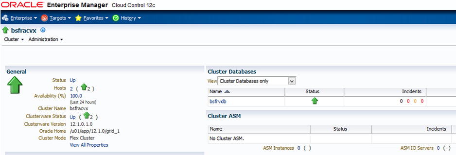
Figure 7-18. OEM 12c ➤ Targets ➤ Select RAC DB ➤ Home Page gives performance, resources, and SQL summary
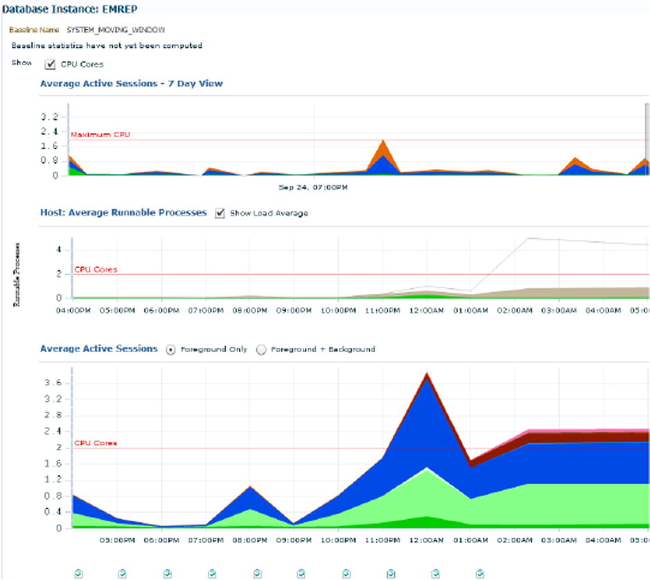
Figure 7-19. Performance Home Page: The stargate of Oracle RAC (and non-RAC) DB tuning in OEM Cloud Control
“Performance” Menu ➤ “Performance Home” homepage:
- A very structured and useful organization of performance-centric links/resources.
- Significant improvement over 10g/11g OEM Grid Control.
- Will ask you to log in with SYSDBA or DBSNMP monitoring credentials.
Understanding the colors on the various graphical depictions and the information/severity level they represent is very important to this approach: generally, the more the reddish the color, the more trouble it is for the RAC DB.
- Greenish/blueish colors.
- Grayish colors.
- Brownish colors.
- Reddish colors.

Figures 7-20. Cluster ➤ Performance: CPU, memory, and disk utilization within OEM12c
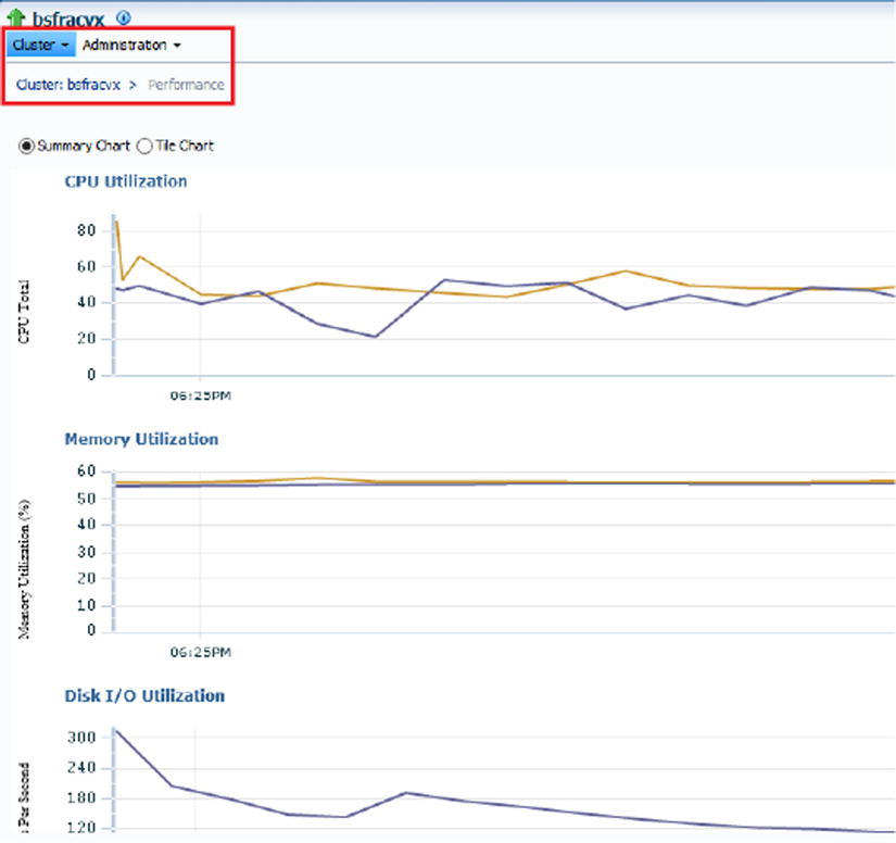
Figures 7-21. Cluster ➤ Performance: CPU, memory, and disk utilization within OEM12c

Figures 7-22. Cluster cache coherency link/menu item: The main link/entry page for RAC cluster monitoring/tuning

Figures 7-23. Cluster cache coherency link/menu item: The main link/entry page for RAC cluster monitoring/tuning

Figures 7-24. Cluster cache coherency link/menu item: The main link/entry page for RAC cluster monitoring/tuning
The preceding examples are just some of many powerful features for a quick n’ easy way of performance tuning RAC clusters within OEM12cR2.
Summary
RAC lies at the most complex end of the Oracle Database Server family spectrum and can be challenging to get one’s arms around, especially for large-scale setups. Managing and optimizing any RAC cluster require a considerable amount of skill, experience, and expertise. This chapter covered most essential knowledge streams related to easy, policy-based, and easy-to-learn management of Oracle RAC clusters. From node evictions to split-brain scenarios, tips/tricks for various OS families, server pools and stretched clusters, and a whole lot more, a wide and expansive range of topics was covered in this chapter to efficiently and effectively cope with/ease the daily load of a RAC DBA/DMA.