Chapter 12
Making Tools and Machining Parts
IN THIS CHAPTER
![]() Peering over the fence at the machine shop
Peering over the fence at the machine shop
![]() Exploring why turning, milling, and EDM are needed
Exploring why turning, milling, and EDM are needed
![]() Touching on tools that cut (ouch)
Touching on tools that cut (ouch)
![]() Turning over a new leaf on CNC lathes
Turning over a new leaf on CNC lathes
![]() Cutting it with carbon (and copper)
Cutting it with carbon (and copper)
![]() Grinding grandly
Grinding grandly
It’s not the work which kills people, it’s the worry. It’s not the revolution that destroys machinery it’s the friction.
— HENRY WARD BEECHER
You’re probably a big fan by now of metalworking machinery and have it in your head that the world revolves around machine tools that bend and shear and stamp and such. Not so fast. As the English poet and cleric John Donne once said, “No man is an island entire of itself; every man is a piece of the continent, a part of the main.” (Sorry to have left the womenfolk out of that one, but what do you expect from a sixteenth-century philosopher?)
I might say something similar, though far less eloquent, about machine tools: No machine tool stands alone; each depends on its brethren — the lathe for its sheet-metal enclosure, the machining center for its turned gears and spindle bearings, the press brake and stamping press for their precision-machined tooling.
Not quite as catchy, is it? But hopefully you get the idea and stand forewarned about the contents of this chapter: Sheet-metal machinery needs lathes and machining centers and grinders and electrical discharge machining (EDM) equipment for the tooling that allows it to transform metal. In sports parlance, a punch press without punches is like a hockey player without a stick, a jockey without a horse. All might look impressive, but nothing’s going to happen without the tools to do the job.
Touring the Tool and Die Department
You might spend your entire life working with sheet metal or welding stuff together and never set foot in a machine shop. That’s okay, although I consider it a shame. I may have started my manufacturing career in a sheet-metal shop, but I ended it in a job shop filled with lathes and machining centers and drill/tap machines, and that’s where my heart is. And if none of those terms makes sense to you, you can either stick around for the 30,000-foot view you’ll receive in this chapter or pick up my other book, Machining For Dummies. (I’m still waiting for my wife to finish it, but my kid says, “Not bad, Dad.”)
The usual suspects
Let’s review some basics. I dig into the details a bit more over the next few pages, but be aware that a “typical” machine shop is filled with lathes and mills. These may be powered by a human being that turns handles and pulls levers (which makes them, appropriately enough, manual machine tools). More likely, they may be powered by servomotors and controlled by a computer, giving then the lofty term, computer numerical control (CNC) machine tools.
The toolroom in a stamping house or indeed in any sheet-metal fabricator is a bit unlike the typical job shop I was just getting all gushy over. For one thing, you’re likely to see more manual equipment. That’s because activities like fixture building and punch sharpening are often easier on a hand-cranked machine, with none of that pesky CNC programming and coordinate setting required by automated machine tools.
 Some shops might disagree with the previous statement. That’s because a properly equipped CNC lathe or machining center can be every bit as efficient on low-quantity production and prototype work as a manual machine. Quick-change workholding eliminates the need for setting coordinate systems. Offline tool presetting avoids having to “touch off” cutting tools. Computer-aided manufacturing (CAM) systems and toolpath simulation software makes proving out a machine program as difficult as pushing cycle start. If your toolroom isn’t leveraging these technologies, you’re missing the boat on improved efficiency.
I’ll take the combo
A fab shop may also include more “half CNCs,” or combo machines, similar to the one shown in Figure 12-1. These are a best-of-both-worlds solution to those not yet ready to purchase or unable to justify the greater expense of a full-blown CNC machine. They can be operated manually by turning the cranks as you would on your toolroom lathe or knee mill, or programmed with a CAM system not unlike the one used to program your punch press. They can even be “taught” how to machine parts, similar to the teach mode used to program many robots (cruise back to the previous chapter if you need a refresher).

Courtesy: Fryer Machine Systems, Inc.
FIGURE 12-1: Combo or “half CNC” machines such as this are a flexible alternative to manual mills and lathes.
The beauty of these machine tools is their lower cost (perhaps half that of a production CNC machine), their ease of use for those unfamiliar with CNC equipment (many old-timers are reluctant to operate them), and their ability to automate tasks that can be challenging to do manually, such as single-point threading and machining bolt hole patterns. Add it all up and combo machines are a flexible machining solution for many tool and die departments.
Facing the hard facts
Toolrooms are also likely to have more grinding and EDM equipment, which are generally more suited to holding the close tolerances called for in stamping dies and other sheet-metal tooling. The same can be said for the hardened tool steels and carbide used to make much of that tooling — most of the time, the best way to machine it is with EDM and grinding, which scoffs at ultra-hard materials.
Justifying their existence
I said it earlier: Nothing happens without tools. In the case of sheet-metal fabrication — whether it’s stamping or bending or punching — those tools are the die shoes, jigs and fixtures, punches and dies, and all the miscellaneous pins, bolts, and other hardware that goes with them. In all honesty, many of these items are purchased off-the-shelf and assembled into whatever turret or bolster plate needs them. But ask anyone who’s worked in a shop: Special tooling requirements are always popping up, and more often than not they are needed that afternoon.
Toolrooms do far more than put out fires, however. Many are fully-equipped machine shops in their own right, able to compete with darned near any production house around. This is a great example of vertical integration. It’s more than a catchy marketing term. “Going vertical” means mastering sheet-metal processing and machining alike, and may also mean taking on secondary finishing processes such as powder coating, painting, and assembly. (I flesh out the first two of those processes in Chapter 15.)
Vertical integration gives your customers “one throat to choke” when procuring manufactured parts. It shortens lead times, and because shops are forced to own each step in the manufacturing process, it often improves quality. And because parts aren’t being shipped all over town to different specialty shops, costs are reduced.
The moral of the story is this: The most successful shops are (or soon will be) those that embrace all types of metalworking, including machining and finishing. Keep that in mind if you’re just getting started in fabricating, as it may alter the path of your education.
Meeting a Few Machine Tools
I mentioned mills and lathes at the start of this chapter, but I didn’t actually describe what they are or what they do. The two are quite different from one another, and within each general classification, hundreds of unique machine configurations exist. Despite their differences, however, all mills and lathes share some basic mechanical similarities:
- Whether lathe or mill, CNC or manual, each has a rotating spindle and a motor to drive it. Gears may be used to increase torque or generate higher spindle speeds than would otherwise be possible.
- All have a table or carriage of some kind that moves in and out, side to side, or up and down (and some do far more than that). In the case of CNC machines, this is called interpolation. These moving parts are called the machine axes (plural for axis), which are not very different from the ones found in the sheet-metal machinery described throughout this book.
- All CNC machines employ a servomotor to drive these machine axes, although even manual machinery has “power feeds” or gear drives to eliminate the endless crank turning that would otherwise occur. These also generate a better surface finish than hand-cranking.
Here’s where the two go their separate ways: If you clamp the workpiece to the table (typically with a vise or fixture), you’re standing in front of a mill. If you attach the workpiece to the spindle (by clamping it in a device called a chuck), you’re operating a lathe.
Lathes and mills also accept cutting tools that remove metal in a process far different than those used in a sheet-metal shop — the difference being that lathe tools are mounted on a turret or tool block and remain stationary, while tools used in a milling machine or machining center are placed in a rotating spindle.
Because of these magical things called cutting tools (which I describe in additional detail later in this chapter), the processes by which metal is manipulated in a machine shop are far different than those used by a fabricator. Hang on as we dive into the specifics of how it all works.
 If a press-brake operator were to make a new dining room table, he or she might shear the individual pieces, bend them, then punch a few holes for some rivets or screws before assembling them. A welder would saw or flame-cut chunks of plate stock and simply weld them back together. A milling machine operator? She’d just carve the thing from a solid block of metal.
Turning terrifically
Because I’m an old lathe guy, I’ll begin there. Lathes make round parts through a process called turning. (Although, some misguided souls refer to it as lathing. Please be polite when correcting them.) The screws that hold your Xbox case together were turned. So too were those annoying dowel pins in your IKEA furniture, the washers you’re using to shim the corner of the coffee table, and the candlesticks you gave to Mom for her birthday.
In a toolroom, lathes might be used to rough and semi-finish a punch for a stamping operation. In most cases, these would go on to a cylindrical grinder for finishing after heat treatment, although an increasing number of shops are turning (pun intended) to hard turning with cubic boron nitride (CBN) and ceramic cutting tools. (Scope out Figure 12-2 for a quick visual.)

Andrey Eremin/Shutterstock
FIGURE 12-2: Despite the increasing popularity of CNC machinery, engine lathes remain a common sight in most toolrooms.
Other ways a lathe might be put to use include turning shafts and retaining pins, threading bolts and other fasteners, boring bearing housings, and so on. Simply put, if it’s round, it probably spent time on a lathe. Here are some of the different kinds of lathes you’re likely to encounter during your manufacturing journey:
- Engine lathes: They don’t make engines, nor do they contain one, although some of the earliest lathes (and indeed most machine tools) were connected via a series of belts and pulleys to a steam engine, hence the name. Today’s engine lathes are characterized by a carriage that moves longitudinally, on top of which rests a cross-slide for radial-type work such as cutting a workpiece to length, and a compound rest that’s used for cutting tapered part features and for single-point threading.
- Toolroom lathes: A toolroom lathe is a lighter duty, more accurate version of an engine lathe. It too employs a gearbox and leadscrew that can be used to single-point threads and power the slides, and like an engine lathe, has a tailstock and live center to support long workpieces. You can also take the live center out of the tailstock and replace it with a drill bit for making holes in the end of the workpiece.
- CNC lathes: Unlike most manual lathes, CNC lathes have a turret mounted on top of the slide arrangement that can accommodate multiple turning tools. This eliminates the need to stop the machine when switching from a drill to a threader or cutoff tool, for example, and allows continuous execution of the CNC program (called G-code). Some are equipped with “conversational” controls that eliminate the need for offline programming systems (most combo machines boast conversational programming capabilities, making it easy to program the machine on the shop floor).
This list is nowhere near complete. Many machine shops use Swiss-style screw machines to turn very small and/or long, skinny parts. Live-tool lathes have milling attachments that allow features such as slots and cross-holes to be machined, eliminating secondary operations. Multispindle lathes, as the name suggests, turn multiple parts simultaneously. Multitasking lathes have a machining center-style spindle for milling operations and may have a sub-spindle for turning the back side of a workpiece. That said, the three types of lathes listed earlier represent the typical lathes found in typical toolrooms in typical fabricating shops everywhere. How typical.
 I may have misled you, dear reader, when I mentioned the various household uses of washers and screws a couple paragraphs back. Those parts probably weren’t turned. They could have been, but when making gazillions of them for the likes of IKEA or Ace Hardware, manufacturers rely on the most cost-effective production method. For washers, this is stamping. Pick one up and you’ll see — the edges on one side are slightly rounded, while those on the opposite side are slightly sharp. These are the telltale signs of a stamped metal part. As for the screws, they were probably cold-headed, a process that uses metal wire and a forming die to crank out fasteners faster than a first-date kiss with the minister’s daughter.
Milling majestically
You may have noticed the seemingly interchangeable terms milling machine and machining center graffitied across the preceding pages. Sorry for the confusion; the two aren’t interchangeable. I mean, feel free to call them whatever you want, but mill, knee mill, milling machine, and especially Bridgeport (even those that aren’t actually made by that oft-imitated company) all refer to a hand-cranked machine tool invented more than 80 years ago (see the eminently important historical sidebar “Cutting it up in Connecticut”).
Machining centers, on the other hand, are by definition CNC machines. Most have three axes of motion (X, Y, and Z) and a spindle that is oriented vertically, hence the name vertical machining center (VMC). Accessorizing one with an “indexer” is no big deal (it looks sort of like the lazy Susan on your kitchen table, but tipped up sideways), giving operators access to multiple sides of the workpiece in a single handling.
Similarly, a rotary table (also known as a “4th axis”) allows complex shapes like turbine blades and gears to be machined (see Figure 12-3). And as with the turret on a CNC lathe, VMCs are equipped with carousel or magazine-style automatic tool changers (ATCs), providing non-stop machining.

Courtesy: Autodesk
FIGURE 12-3: Though they look virtually identical, indexers can only rotate to fixed positions, while a 4th-axis rotary table provides simultaneous movement.
Laying down on the job
Knee mills, combo machines, and VMCs account for the biggest slice of the tool-room milling-machine pie, but several other notable examples exist, starting with horizontal machining centers, or HMCs. Though at first glance it may appear that way, an HMC isn’t a VMC that’s been flipped on its backside. HMCs offer several distinct advantages over their vertical brothers:
- Chip flow is substantially better than on a VMC, improving tool life and part quality. (Chips are the little curls of metal removed by cutting tools on lathes and mills.)
- Machine accuracy is generally better as well, as is rigidity. This also helps extend tool life and improve part quality.
- Because HMCs are usually equipped with pallet changers and large tool magazines, unattended machining is easier to achieve.
The downside to an HMC is machine capacity — dollar for dollar, table travels on a VMC cost roughly half that of a comparable HMC. This doesn’t matter to someone who’s machining smallish parts all day (say anything smaller than a clock radio), but it is a big deal for those building suitcase-sized progressive dies.
Five ways better
That rotating table I mentioned a few paragraphs back? Shops have been mounting them as well as indexers to their VMCs for decades, allowing them to produce increasingly complex parts while reducing the number of operations needed to make them. At some point, though, some clever machinist, probably having spent the weekend riding the Tilt-a-Whirl at the county fair, bolted a rotary table to the top of another rotary table, and thus invented the tilt-rotary, or trunnion-style table.
 Trunnions allow machinists to grip a block of metal along its bottom edge and machine the top and adjacent four sides of the workpiece. The part can then be completed by flipping it over and milling away the bottom; instead of six separate operations, the part is done in just two. If so equipped, the three VMC axes can move simultaneously with the two axes of the trunnion, producing some complex work indeed. This is called 5-axis machining.
It’s a straightforward affair to equip most VMCs with a trunnion table. All that’s needed are a couple electrical connections and software to control the additional axes (the fourth axis and fifth axis interfaces). However, many machine builders offer true, 5-axis machining centers, designed specifically for this type of machining. These are available in a variety of configurations and capabilities and are quickly becoming the new alpha dog of the machining center pack.
Going gantry
Those making large welding jigs or assembly fixtures may employ a gantry mill, a humungous machine tool that in some cases is big enough to accommodate a pickup truck or airplane wing. The frame holding the vertical milling spindle is shaped like an upside-down U, with the spindle moving horizontally across the upper rail (called a guideway). This contraption is in turn mounted to a pair of precision tracks and rides lengthwise down the guideways.
Some are equipped with “nutating” heads that can machine at right- and compound-angles (similar to 5-axis machining centers), while others have two or more spindles for cutting multiple part features simultaneously. If you’re tasked with machining a large-form die for stamping out F-150 door panels, this could very well be the machine you use.
I’m so bored
Sorry if that’s true, but don’t worry; I’m nearly done with milling machines. Take an HMC, add a Bridgeport-style quill, quite possibly remove the sheet metal enclosure, and you have a boring mill.
Now that I said that, I just realized you might not grok the meaning of the word “quill.” Known by CNC programmers as a “W-axis,” a quill rides inside the main spindle housing and, once the Z-axis (the part that travels into and out of the workpiece) has been brought into position, extends the cutting tool inside, allowing otherwise inaccessible part features to be machined and producing very straight, accurate holes.
Like gantry mills, horizontal boring mills are also often quite large and are popular with those shops machining tractor bodies and other earthmoving equipment. Go visit a John Deere or Caterpillar factory and you’ll see plenty of boring mills there (you should probably call for an appointment first).
Jig borers were once the Jedi Knights of the tool and die room. Invented after World War I, they are essentially ultra-precise knee mills that are designed to machine extremely accurate holes in jigs, fixtures, and dies. Take that accuracy a step further and you have a jig grinder, which has an orbiting grinding wheel instead of a cutting tool. Both have largely been replaced by EDM and high-end CNC machining centers, although some builders still market CNC versions of jig boring and jig grinding machines.
Staying Sharp with Cutting Tools
Just as press brakes need bending dies and punch presses need punches, so too do machining centers and lathes need end mills, drills, and other cutting tools. Without these precision hunks of metal, machine tools do nothing but sit there using up valuable floor space. I talk about the carbide and high-speed steel needed to make these tools in Chapter 9, and I’ve been giving sheet-metal tooling in general its fair share of coverage throughout the book, which is why I’ll now take a page or two to discuss cutting tools. Bear in mind that we’re only scratching the surface of the subject, and that a wealth of additional information is available in books, classes, and the various cutting-tool manufacturers’ websites.
No one likes to be put into a box, and this includes cutting tools. But if you’re looking for a cutter to mill a slot or drill a hole, it’s good to know which tooling catalog to pick up or hyperlink to click on, which is why most cutting tools fall into one of two categories — rotary or stationary — and correspond to the type of machine on which the cutting tool is used.
Spinning ’round: Rotary tools
Generally speaking, rotary cutting tools such as end mills and slitting saws are associated with milling operations. In this case, the tool spins while the workpiece moves past it, thus allowing the cutter to shave away material as it passes. Here are a few examples of the most common rotary tools:
- Drill bits: Holemaking is the most common of all metalworking operations, and aside from the holes made with laser or electron beams (a surprising number), most are drilled with a drill bit. It should therefore come as no surprise that so many different types of drill bits exist, everything from Jobbers and screw machine–length to indexable, center, and spade drills. Most resemble pencils, but with a flatter point (usually with an included angle ranging from 118 to 140 degrees) along with a chisel-like cutting edge and no rubber eraser. Drills with two “flutes” are the most common (these are spiral, barber pole–like grooves running along the outside), but three-fluters (which offer higher penetration rates and straighter holes) are also available.
- Reamers: Drill bits leave much to be desired in terms of surface finish and hole quality; reamers are often used to improve both. These are multi-fluted cutting tools that remove a relatively small amount of material, straightening the hole and smoothing the walls as they pass. The most common is a chucking reamer, although hand reamers, fluting reamers, machine reamers, and others are also available. Adjustable reamers are particularly useful in a toolroom, allowing the operator to turn a small screw to tweak the hole size when the tool wears.
- End mills: An end mill looks much like a drill, except the end is usually square or round rather than pointed. Two- to four-flute versions are most common, although some manufacturers have introduced five-flute, seven-flute, and even eleven-flute end mills. Despite their being kissing cousins to drill bits, end mills are designed to cut radially (side to side), “interpolating” part features such as pockets and slots. That said, center-cutting end mills do offer limited drilling capability and can also be made to “tornado” into a workpiece (called helical interpolation), tracing a circular toolpath while simultaneously driving into the workpiece longitudinally.
- Threading: Next to holemaking, threading is one of the most commonly performed of all metal-cutting operations. Most often it’s done with a tap, a tool shaped like a bolt or screw but with two or more thread-cutting flutes running along its length. On a CNC machine, the spindle’s linear motion must be precisely synchronized with its rotation so as to avoid breaking the tap or stripping the threads, but on a manual machine, the tap is often floated into a pre-drilled hole by feel. Also on CNC machines, many threads are now generated using a special thread-cutting end mill and helical interpolation called — appropriately enough — thread milling.
The list goes on and on. Face mills are used to machine the top surface of a workpiece. Shell mills are soup can–shaped end mills with no end-cutting capability used to cut shoulders and slots. Mold makers use button cutters to rough out pockets. Slotting cutters and slitting saws cut slots. Corner-rounding end mills cut neat radii along the top edge of a workpiece to make it look pretty.
Most rotary cutting tools are available in solid carbide, high-speed steel, and “indexable” versions, the last of which has little chunks of precision-ground carbide attached to steel bodies that are recycled when dull. These offer the lowest “cost per edge,” an important consideration for most shops, but are not as effective as tools made of solid carbide. It’s for this reason that most milling cutters around 1/2 inches and smaller are carbide, while larger cutters are usually indexable (see Figure 12-4).

Courtesy: Sandvik Coromant
FIGURE 12-4: A “high-feed” indexable milling cutter being used to rough out a pocket in a steel workpiece.
Hold still: Stationary tools
Contrast this with turning operations, where the tool is held stationary and the workpiece itself spins. Take a peek inside any CNC lathe. There you’ll find a turret filled with “stick tools” that have square shanks and a carbide insert on one end much like those found on an indexable milling cutter. Of course, you’ll see drill bits, reamers, and taps there as well (though not rotating), since a big percentage of turned parts have holes and threads in them.
In no particular order, here are the most commonly used turning tools:
- Boring: Once a hole has been drilled, it often needs to be enlarged or otherwise finished. I mention reamers earlier in this chapter, but these are just one piece of the hole-finishing puzzle. Boring tools can be used to cut counterbores. They might be programmed to trace a complex internal shape or used to cut a bore for which a reamer is unavailable or inappropriate. Boring tools are also used on milling machines and machining centers but require an adjustable boring head and can only be used to cut straight holes — no contours or profiles allowed.
- Grooving: Grooves are a common part feature, used to contain rubber O-rings and seals, snap rings to hold a mating component in place, or to “relieve” the groove’s adjacent diameter, effectively creating a sharp inside corner when placed against a shoulder. Grooving tools can be classified as external, internal, or face groovers (an operation referred to as trepanning). Because of all the different widths, shapes, and depths, never mind the universe of workpiece materials, grooving inserts galore exist. Some groovers are designed as “parting tools” that are used to cut finished parts from a length of bar stock clamped in the lathe chuck.
- Profiling: No, I’m not talking about the politically-charged type of profiling, but rather the kind used to turn the outside of a shaft. Profiling inserts (most folks just call them turning tools) are available in various square and parallelogram shapes (that is, diamonds) and are responsible for the lion’s share of metal removal during turning operations. Turning and facing a shaft, for example, might use an 80-degree, 55-degree, or 35-degree diamond insert, the difference being the included angle of the cutting edge.
- Threading: Internal threads are most often tapped, but bolts, fasteners, and other parts with threads on the outside are usually “single-pointed” using V-shaped threading inserts (this can be done on larger internal threads as well). As with tapping, synchronization between the spindle motor and axis motion is required — on a CNC machine, the computer and its servo systems take care of this, but on an engine or toolroom lathe, a gear arrangement drives the carriage at the precise rate needed to cut the thread.
This section on lathe tooling has thus far only mentioned indexable tools, but back in the day, lathe machinists used square blocks of sharpened high-speed steel, or “brazed” tool bits with little pieces of carbide welded on top. These are still available and there may be plenty of shops still using them, but doing so is a monumental waste of time and money (sorry for offending anyone). There’s simply no reason not to embrace indexable lathe tooling, as well as other modern cutting-tool technologies, whether they’re used on a spanking-new CNC machine or the oldest, ugliest engine lathe in the shop.
Increasing Your Carbon Footprint with EDM
Now that you have a handle on what is meant by machining, what’s less clear is how to define a chip. If you’ve ever had your finger sliced open by one, you might remember it as that Frito-like bit of razor-sharp metal that caused you to spend three hours at the emergency room and made you miss bowling that week.
But some machining processes make chips that are so small they look like little more than black sludge in the bottom of the machine tool. One process responsible for making that sludge is electrical discharge machining, or EDM. This process works by sending a pulse of electricity through an electrode placed in close proximity — only a hair or two distant — to an electrically conductive workpiece (meaning metal, carbide, diamond, and some ceramics). Between the two sits a non-conducting “dielectric,” such as non-conducting oil or deionized water, which is continuously circulated around and sometimes through the electrode to flush away waste material.
With each pulse, a spark measuring upward of 20,000 °F jumps like a miniature lightning bolt from the electrode to the workpiece, melting or vaporizing a tiny amount of material. This process is repeated every few dozen microseconds, gradually “eroding” the workpiece into the desired shape.
EDM is a hugely complex subject, full of talk about pulse durations, polarity, peak current, and other topics EDM guys discuss at their secret late-night parties. For now, what’s important to know is that EDM is one of the superheroes of toolmaking, without which this hugely necessary vocation would be nearly impossible (despite what your granddad says, who once made molds and progressive dies “without that newfangled electrical thing”).
Sink or swim
Also known as ram, cavity, and conventional EDM (see Figure 12-5), sinkers use an electrode that’s been previously machined into a mirror image of the desired workpiece shape. It’s an ideal way to machine injection-mold cavities, coining dies, and complex shapes in workpieces that cannot be produced via conventional means — square internal corners in a workpiece, for example, or tiny recesses too small or deep for a cutting tool.
Courtesy: MC Machinery Systems, Inc.
FIGURE 12-5: An example of a sinker EDM using a graphite electrode to rough burn a steel workpiece. The smoke emanating from the top of the dielectric oil is what gives these machines the nickname “stinkers.”
Aside from the high-frequency stream of sparks common with all EDM tools, sinkers also employ “orbiting” to remove metal. In this case, the electrode is plunged into the workpiece using a reciprocating up and down motion, and then moved around to shape the cavity, often in multiple axes simultaneously. This provides improved size control over plunging and allows even simple electrodes to make complex shapes.
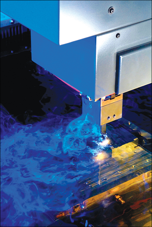
Wired up
Instead of a previously-machined graphite, copper, or tungsten electrode, wire EDM (WEDM) uses a spool of consumable wire — the electrode — that passes through a tortuous series of wheels and rollers, over an electrical contact, through a doughnut or V-shaped guide, through the workpiece into another set of guides on the opposite side, across an opposing contact point, and onward to a waste bin or take-up reel for disposal of the now spent electrode (see Figure 12-6).

Courtesy: MC Machinery Systems, Inc.
FIGURE 12-6: Though wire (and sinker) EDM is generally done while submerged in water or oil dielectric, “open skim” cuts like this make it easy to see the spark between the wire and workpiece.
WEDM’s primary role is punch and die–making, but it can also be used to cut slots, grooves, holes, and irregularly-shaped features in everything from medical parts to spline gears. Workpiece tapers up to 45 degrees or so can be produced, as can curves more sweeping than a modern art exhibition. The beauty of wire EDM, and indeed all EDM processes, is its ability to cut very hard materials with impunity. WEDM is also extremely accurate, able to hold tolerances of +/- 0.0001 inches (0.002 mm) or better and surface finishes smoother than the proverbial baby’s bottom. And because the electrode used with “traveling wire EDM” (an old term that’s rarely used anymore) is very thin — about 0.008 inches, give or take — material waste is extremely low.
Grinding Is Groovy
Grinding is an abrasive metalworking process. It rips away bits of metal using a “friable” stone wheel. This means it breaks apart during use, uncovering fresh, sharp cutting edges and eliminating the “wheel loading” that would otherwise occur. This process may not sound very accurate, but grinding is in fact (or can be) one of the most precise of all metalworking processes, second only to lapping and perhaps honing.
Grinding wheels come in all shapes and sizes, but in general are disc-shaped with a hole in the center for attaching the wheel to a rotating spindle. The materials used to make grinding wheels range from aluminum oxide to silicon carbide to zirconia alumina. All contain tiny bits of what are essentially very tiny, very sharp rocks, held together by a bonding agent — phenolic resin is common, although some use metal or even rubber-based bonding agents. In general, grinding comes in the following flavors:
- Centerless grinding: Long shafts and bars are often ground on a centerless grinder. This machine contains a rest blade to support the bar or workpiece, a regulating wheel to spin it, and of course, a grinding wheel, which sits opposite the regulator and removes material at a fairly good clip compared to other grinding processes. Beware, though: Cylindrical grinding can cause lobing or triangulation of the target diameter, a condition that can be avoided through meticulous machine setup and Jedi-like grinding knowledge.
- Cylindrical grinding: Many turned parts leave the lathe and head on over to the cylindrical grinder for finishing (usually after hardening via heat treatment). Here they are mounted between a pair of centers and rotated via a “drive dog,” whereupon the grinding machine operator feeds a wheel roughly the size of a tricycle wheel into the side of the workpiece. Cylindrical grinding has long been used to make punches, bearing journals, and similar close-tolerance cylindrical part features, but is gradually being replaced by “hard turning” on CNC lathes using CBN or ceramic cutting tools.
- Surface grinding: As its name implies, surface grinding is used to grind surfaces flat. A common fixture in most toolrooms, a typical surface grinder has a magnetic chuck on which a piece of steel or similarly magnetic material is placed and then ground via the overhead reciprocating wheel. It is a relatively slow process, usually removing just a few ten-thousandths of an inch per pass, but like all grinding processes, is capable of close tolerances and fine finishes.
Many other types of grinding exist. Creep-feed grinding removes large amounts of material in a single pass, and in some cases competes with milling and turning machines. Double-disc grinding grinds two sides of a workpiece simultaneously, making both very flat. Internal grinding is used to finish holes and prepare bores for honing. Electrochemical grinding uses electrical current and a chemical electrolyte in a process similar to EDM. There might be a bench or pedestal grinder in your garage that you use to sharpen your lawnmower blade — either can be found in most machine shops. And hand-operated power tools are often equipped with grinding discs or stones to polish surfaces or prepare them for subsequent welding operations (something I discuss in Chapter 10).