

Migration to Cloud with IBM Power Systems Virtual Server
This chapter provides information about how to migrate IBM i LPARs on customer’s data center to virtual machines (VMs) on IBM Power Systems Virtual Server.
A migration strategy is the most important step in our migration process. Every customer has its own business needs, and the correct strategy can drive the migration project to success.
In this chapter, we discuss the different tools and techniques we can use to transfer our IBM i workloads and the requirements, challenges, and advantages on each method.
This chapter includes the following topics:
2.1 IBM i and data migration
When moving workloads to a new system, many issues must be considered based on business rules, technical resources, and the environment.
IBM Cloud Power Virtual Servers features specific requirements and challenges based on its online and self-service nature. The following IBM i constrains also must be considered:
•We have no access to the hardware layer. No HMC or Storage direct access is provided; therefore, hardware replication cannot be used.
•We have no access to the data center. A physical tape cannot be sent to perform a restore.
•No physical tape is available for backup or restore operations.
•Your system is in a remote facility and communications can have some latency, depending in your location and link type.
•Most IBM i backup devices use SAS or Fibre Channel connections with a proven reliability and fast transfer rates. Network backups are slow, and even backups to disk can look slow when compared with physical or virtual tape.
•The amount of third-party backup software for IBM i is not so wide, and a small portion of them use network to transfer data.
At times, you must consider the following business and technical constrains:
•You do not have enough space for backing up to disk.
•Your communications are not fast enough to transfer data as you need.
•You use an outdated or unsupported operating system releases.
•You have third-party software with serial number licensing and validation.
Most IBM i shops rely on physical media for backup and restore, and their data recovery strategies include this media as a main option, even when a replication mechanism is in place.
When data must be moved without disrupting the business operation, replication methods or a migration software setup can be used to reduce the backup window. PowerHA and third-party products provide solutions to transfer information gradually and synchronize systems while they keep running (see Figure 2-1).

Figure 2-1 From PowerHA SystemMirror for i
But advantages are gained when the instance is running on the IBM Power Systems Virtual Server environment:
•The IBM i instance is migrated seamlessly to a new server with Live Partition Mobility at no cost when the original server is being maintained or is failing. This issue results in no charge high availability, which is the default behavior but can be tuned.
•Instant snapshots can be taken from your IBM i instances.
•Clones can be taken from our disks with just a couple of clicks.
•Instances can be exported to an OVA and saved for later use or migrated to a new region.
•Network speed is fast:
– Internet connection can scale 1 Gbps - 10 Gbps.
– Local networking is redundant, supports Jumbo Frames and link aggregation, and the link speed is over 10 Gb.
– Most of these features are transparent to the user.
•A new iSCSI Virtual Tape Library offering is available that uses the fast networking facility.
•IBM Cloud Object Storage can be accessed from the internet or privately, with a cost effective offer.
•IBM Cloud Object Storage is fast and can be accessed with native or open source software.
•BRMS or IBM Cloud Storage Solution for i does not need to be installed. Instead, select the license feature when creating an instance and the standard image includes the product with a basic configuration.
•When all of the data cannot be uploaded to the migration window, IBM Cloud can provide the Mass Data Migration Device, which is a storage device with up to 120 TB and multiple alternatives to save data.
Many resources are available that can be used to migrate data from on-premises systems to IBM Power Systems Virtual Servers. Therefore, planning is crucial to the migration process.
2.2 Backup and Restore migration
Most IBM i shops use and rely on physical tapes for backups of day-to-day operations, and migrating workloads to a new system is not an exception.
Tapes are the main migration method when moving data (and even the operating system) from the system to a new box.
Unfortunately, physical tapes cannot be used with cloud environments; therefore, alternative methods must be used, such as saving data to disk and the network for transfer.
When data is moved to the cloud, data must be uploaded by using the network. At times, the target systems can be accessed, and an intermediate “bucket” is used to reach the target environment. IBM Cloud Object Storage can be a useful environment for this intermediate storage.
Because the amount of data that is being migrated affects the time that it takes to transfer to a target environment, compression can improve the process by reducing its size.
Virtual media can be very large, depending on the amount of data that must be transferred. Consider choosing the correct size for your virtual media so that you can use parallel file transfers when possible and improve transfer times.
Media types often use UDF and ISO formats because they can be combined with virtual optical devices. Also, their size can be 4.7 GB if you want to create a physical media for your own purposes or as large as 1 TB in the latest IBM i releases.
For more information about virtual media capacities, see this IBM Support web page.
The following backup options are available on IBM i:
•Native commands: SAV, SAVLIB, SAVDLO, SAVCFG, SAVSECDTA, and menu GO SAVE.
•Backup and Recovery Media Services for i (BRMS): A complete backup solution for IBM i environment with a many features to automate your backup and restore process.
In this section, we discuss how can we migrate data by using the different methods:
•Full System SAVE and RESTORE:
– BRMS and IBM i Cloud Storage Solutions
– Native GO SAVE and GO RESTORE menu and options
•Partial restores
•Back up your system when not enough space is available
IBM Cloud provides Cloud Object Storage for storing information. Data can be uploaded to Cloud Object Storage by using SSL, VPN, or dedicated communications to transfer our backups.
A software option is available that is called IBM Aspera®, which improves data transfers with IBM Cloud Object Storage and upload backups by using multiple streams.
When the amount of data to be transferred makes it impossible to use the network, IBM Cloud can be used to send a Massive Data Migration device. This portable storage device can save up to 120 TB and then, this data can be uploaded directly to IBM Cloud network, which avoids direct file transfers from our data centers.
2.2.1 Migration with partial saves and restores
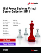
Partial restores can consist of multiple save files, ISO images with virtual optical media, or virtual tape images with which a system can be backed up in parts and then data is transferred to the new Power Virtual Server instance by using FTP, SFTP, SCP, or any other method.
The lack of HMC access forces users to use restart mechanisms and requires that an empty VM instance is created with a working IBM i operating system. Partial restores can be a good option to migrate our LPARs when the operating system images that are provided on IBM Cloud fit a user’s needs.
This scenario is easier because the target system already is running. By using a working IP address, communications can be checked. Often, images include the latest resaves and PTFs and some of the following software that is needed to run workloads in the IBM Power Systems Virtual Server are in place (see Figure 2-2):
•BRMS with basic policies
•IBM i Cloud Storage Solution (5733ICC) running with certificates
•SSL certificates are ready for IBM Access
•YUM is installed
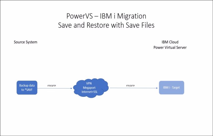
Figure 2-2 Save and restore by using save files
The sample backup and restore scenario that is shown in Figure 2-2 on page 17 includes the following steps:
1. Create the Power Virtual Server service in one location (in this example, Dallas 13).
2. Create an IBM i instance or LPAR with an existing image and add the needed resources with at least six disks, 0.25 CPUs, and 8 GB of memory so that the VM runs smoothly. This system requires more space for backup files when restoring.
|
Note: Correct sizing is recommended. Request such a study from IBM or an IBM Business Partner.
|
3. Communications must be set up between the local network and IBM Cloud so that the system that was created from our source data center can be reached.
4. Some changes are made on the target server by using the console:
CHGSYSVAL SYSVAL(QCTLSBSD) VALUE('QCTL')
CHGSYSVAL SYSVAL(QAUTOVRT) VALUE(*NOMAX)
CHGSYSVAL SYSVAL(QSECURITY) VALUE('40')
CHGSYSVAL SYSVAL(QJOBMSGQFL) VALUE(*PRTWRAP)
CHGSYSVAL SYSVAL(QJOBMSGQMX) VALUE(64)
CHGSYSVAL SYSVAL(QJOBMSGQSZ) VALUE(16384)
CHGSYSVAL SYSVAL(QJOBMSGQTL) VALUE(16384)
CHGSYSVAL SYSVAL(QQRYDEGREE) VALUE(*OPTIMIZE)
CHGTCPA TCPKEEPALV(20) TCPRCVBUF(1048576) TCPSNDBUF(1048576)
CHGSHRPOOL POOL(*BASE) ACTLVL(4000) PAGING(*CALC)
5. Start *FTP or *SSHD servers to allow file transfer:
STRTCPSVR *SSHD
STRTCPSVR *FTP
6. On the source system, enough disk space is needed so that the system can be backed up to disk by using Save Files or IMAGE CATALOG (optical or tape). In this example, Save Files are used. A control language (CL) with all the commands is recommended, as shown in the following example:
CRTLIB BKPIBMI
CRTSAVF BKPIBMI/SAVSECDTA1
SAVSECDTA DEV(*SAVF) SAVF(BKPIBMI/SAVSECDTA1)
CRTSAVF BKPIBMI/SAVCFG1
SAVCFG DEV(*SAVF) SAVF(BKPIBMI/SAVCFG1)
CRTSAVF BKPIBMI/MYLIB1
SAVLIB LIB(MYLIB1) DEV(*SAVF) SAVF(BKPIBMI/MYLIB1) SAVACT(*LIB) SAVACTWAIT(30) SAVACTMSGQ(*WRKSTN)
Here, all of the libraries that are needed to migrate are saved:
CRTSAVF BKPIBMI/SAVDLO1
SAVDLO DLO(*ALL) DEV(*SAVF) SAVF(BKPIBMI/SAVDLO1)
CRTSAVF BKPIBMI/SAVIFS1
SAV DEV('/QSYS.LIB/BKPIBMI.LIB/SAVIFS1.FILE') OBJ(('/home/')) SAVACT(*YES)SAVACTOPT(*ALL)
All files that must be migrated are saved on IFS.
7. Upload the Save Files are to the target system.
8. On the target system, create the temporary library and the empty Save Files on it.
9. Transfer backups to the target LPAR by using FTP, FTPS, or SFTP. In this example, FTP is used.
10. End the subsystems:
ENDSBS *ALL *IMMED
11. Restore the user profiles and security:
RSTUSRPRF DEV(*SAVF) SAVF(BKPIBMI/SAVSECDTA) ALWOBJDIF(*ALL) OMITUSRPRF(QSECOFR)
12. Restore the configurations:
RSTCFG OBJ(*ALL) DEV(*SAVF) SAVF(BKPIBMI/SAVCFG1) SRM(*NONE) ALWOBJDIF(*ALL)
13. Restore all your libraries, one by one:
RSTLIB SAVLIB(MYLIB1) DEV(*SAVF) SAVF(BKPIBMI/MYLIB1) MBROPT(*ALL) ALWOBJDIF(*ALL)
14. Because Save Files are used for this example, deferred mode cannot be used. Therefore, the previous step must be repeated to avoid errors with logical files.
15. Restore the documents:
RSTDLO DLO(*ALL) DEV(*SAVF) SAVF(BKPIBMI/SAVDLO1) ALWOBJDIF(*ALL) SAVASP(*ANY)
16. Restore folders and files from IFS, which can be one or more save files to restore:
RST DEV('/QSYS.LIB/BKPIBMI.LIB/SAVIFS1.FILE') CRTPRNDIR(*YES)
17. Restore the authorities:
RSTAUT *ALL
18. Review the messages. If an error occurs and the restore in unsuccessful, attempt the restore again.
19. Check the devices, line descriptions, and any configuration that affects correct system start.
20. Adjust the net name:
CHGNETA SYSNAME(MYIBMI) LCLCPNAME(MYIBMI) LCLLOCNAME(MYIBMI) DTACPR(*ALLOW) DTACPRINM(*REQUEST) NETSERVER((MYIBMI *ANY)) NWSDOMAIN(MYIBMI) ALWVRTAPPN(*YES) ALWHPRTWR(*YES)
21. IPL the target system:
PWRDWNSYS *IMMED RESTART(*YES) CONFIRM(*NO)
22. Check and validate the new system. If the system passes validation, the new server can be published.
2.2.2 Full system backup and restore by using native commands
Full system backup saves all of the operating system’s configurations, security, and data to media to perform a full system restore from scratch on a new system.
This process is the most traditional migration method. Most customers are confident when performing a full system backup by using physical tape devices or Virtual Tape Libraries (VTL) because this process is part of the Disaster Recovery procedures.
IBM i can be installed from this special backup, starting with License Machine Code (SLIC) and then the operating system. However, because cloud environments cannot use the physical media that is required for a “D” IPL, a different procedure must be used.
On IBM Cloud Power Virtual Servers, the VM cannot be started by using network installation parameters, and license keys and IP addresses are needed to identify the correct Ethernet adapter to use when restoring the system. Therefore, a starting point must be created by using a new empty instance that uses the target operating system.
At the time of this writing, the following operating systems are supported in IBM Cloud Power Virtual Server service:
•V7R1 with extended support
•V7R2 with support (but was commercially withdrawn)
•V7R3 with regular support
•V7R4 with regular support
An IBM i instance must be created. For more information, see 1.2, “Creating a Power Systems Virtual Server” on page 3.
When restore must be done from this virtual media, special requirements that are based on cloud characteristics are important. The new iSCSI VTL for IBM i or an IBM i NFS server that is combined with TFTP service can be used so that the system can use BOOTP and load the SLIC that is necessary to IPL.
In this section. a temporary IBM i VM with NFS and TFTP is used to install the system from the full system backup media. This special restore process works with Virtual Optical media, and the backups must be done on this media.
Some specific requirements must be met to perform this migration and some of them need time to be provisioned. Therefore, good planning is essential for success.
The following Bill of Materials and services was used:
•Target system: IBM Power Systems Virtual Server with IBM i and enough resources for data and workloads.
•Network installation server: IBM Power Systems Virtual Server with IBM i. At least 1 core and 32 GB, and enough disk Tier1 for backup images.
•Communications between source and target system: Often, a Direct Link Connect between Power Virtual Servers and IBM Cloud VSI environment, and a Virtual Router Appliance to route traffic between VLANs and enable IPSEC tunnel to the on-premises environment, are required.
•Optional: Space in Cloud Object Storage to store the backup.
•An NFS server on the source environment to back up data. We recommend the use of any version of Linux (Red Hat Enterprise Linux, Centos, Fedora, SUSE, Debian, and so on). The example that is presented here was made by using Ubuntu Server.
•A private network on the IBM Power Systems Virtual Server that connected to both servers.
|
Important: A ticket with IBM Support is needed to make the private network VLAN available so that every system that is connected to this VLAN can see each other.
|
•Source System: Enough available disk for backup.
|
Tip: When a disk is not available on the source system, use an NFS server or a Mass Data Migration device for backup purposes.
|
Setup process

Figure 2-3 IBM i Migration that uses GO SAVE option 21
As shown in Figure 2-3, different mechanisms are based on resources and the migration strategy that is used.
For example purposes, the process includes the following steps:
1. Back up IBM i by using GO SAVE menu Option 21 and save to the NFS server disk by using the Image Catalog with Virtual Optical media.
2. Transfer data without compression to IBM Cloud Object Storage by using the internet and SSL.
3. Download data from IBM Cloud Object Storage to IBM i NFS Server by using IP address 192.168.80.12.
4. Install IBM i on the target server. The IP address is 192.168.80.11. The Service Tools Server LAN Adapter IP Address is 192.168.80.21.
Backup process
It is assumed that not enough space is available on the IBM i source server to be migrated. When the disk space is less than 50%, a full system backup can be performed to the disk.
Consider the following points:
•A working Linux partition with enough space is needed to accommodate the backup images. In this example, an Ubuntu server is used, but any distribution can be used. We recommend the use of more than two physical cores and SSDs or SAN-attached storage when possible.
•The NFS directions are based on this IBM Support web page.
•IBM i can back up to an NFS server from V7R2 and later. Previous versions also can back up in this way, but with limitations. Our test environment was validated by using V7R2 and V7R4.
•We recommend installing the latest cumulative PTF package, Technology Refresh, and Group PTFs that are related to TCP/IP, Backup and Restore, and IBM Db2®.
•A cloud-init program also must be installed to communicate with IBM Cloud Power Virtual Server installation process. For more information, see the following resources:
– This IBM Support web page
•Linux and IBM i must see each other in a 1 GB network or faster connection between them.
Complete the following steps:
1. Install the following tools on your Linux partition (see Example 2-1):
– Python3
– NFS Server
– awscli (AWS Client works with most S3 servers)
– PIGZ
Example 2-1 Install Linux tools
sudo apt install python3 python3-pip nfs-kernel-server awscli pigz nfs-common
2. Set up an NFS server on the Linux system. Our source network is IBMi04 with an IP address of 192.168.50.244 and Linux 192.168.50.22, as shown in Example 2-2.
Example 2-2 NFS directory creation
#Create NFS work directory
mkdir /NFS
chmod 755 /NFS
mkdir /NFS/IBMi04
chmod 777 /NFS/IBMi04
# Now edit the /etc/exportfs file
sudo vi /etc/exportfs
# Add the following line and save the file with wq!
/NFS 192.168.50.0/24(rw,sync,no_subtree_check)
3. Restart the NFS service on Linux, as shown in Example 2-3.
Example 2-3 Restart NFS
# Restart NFS sevice
sudo systemctl restart nfs-kernel-server
# Export shares
sudo exportfs -ra
# Validate our shares
showmount --exports localhost
4. At IBMi04, set the Service Tools Server from SST or DST. For more information, see the following resources:
Consider the following points:
– The Line Description that is associated to the IP address must be in the same network as Linux NFS server:
CFGTCP
Option 1
F11
– This command shows our network interface and the Line Description name, as shown in the following example:
ETH01:
DSPLIND ETH01
5. Start Service Tools (SST):
– STRSST

Figure 2-4 SST Main Menu

Figure 2-5 SST Work with Service Tools Server Security and Devices
8. Enter 1, which is the same resource that was found with DSPLIND and press Enter, as shown in Figure 2-6.

Figure 2-6 Select Service Tools Server LAN Adapter
9. As shown in Figure 2-7 on page 25, set the host name, address (which is different from the main interface), gateway address, and subnet mask.
10. “Store” the LAN adapter by pressing F7, deactivate the LAN adapter by pressing F13, and then, Activate the LAN adapter by pressing F14.
11. Press F3 to exit Service Tools.

Figure 2-7 Configure Service Tools Server LAN Adapter
12. Restart the system to take the changes:
PWRDWNSYS *IMMED RESTART(*YES) CONFIRM(*NO)
13. Log in to the system again and add an entry to the host table:
ADDTCPHTE INTNETADR('192.168.50.22') HOSTNAME((NFSSERVER))
14. Mount the NFS share and start creating the virtual media, as shown in Example 2-4.
|
Note: It is important to know how much data must be backed up so that enough virtual media can be created. It is not possible to create the images during the backup process.
|
Example 2-4 Mount resource
# Mount the resource
MOUNT TYPE(*NFS) MFS('192.168.50.22:/NFS/IBMi04') MNTOVRDIR('/NFS')
# Create the empty files - 4 x 10GB virtual optical disks
CALL QP2TERM
cd /NFS/IBMi04
dd if=/dev/zero of=IMAGE01.ISO bs=1M count=10240
dd if=/dev/zero of=IMAGE02.ISO bs=1M count=10240
dd if=/dev/zero of=IMAGE03.ISO bs=1M count=10240
dd if=/dev/zero of=IMAGE04.ISO bs=1M count=10240
# Now we need to create the VOLUME_LIST file entries to tell our device how to change media when the mounted ISO gets full.
echo 'IMAGE01.ISO W' > VOLUME_LIST
echo 'IMAGE02.ISO W' >> VOLUME_LIST
echo 'IMAGE03.ISO W' >> VOLUME_LIST
echo 'IMAGE04.ISO W' >> VOLUME_LIST
15. Create a device description that is linked to the Service Tools Server LAN Adapter, as shown in Example 2-5.
Example 2-5 Device creation
# Create the device
CRTDEVOPT DEVD(SAV2NFS) RSRCNAME(*VRT) LCLINTNETA(*SRVLAN) RMTINTNETA('192.168.50.22') NETIMGDIR('/NFS')
# Vary on the device
VRYCFG CFGOBJ(SAV2NFS) CFGTYPE(*DEV) STATUS(*ON)
16. Initialize the virtual optical media, as shown in Example 2-6.
Example 2-6 Loading images to catalog
LODIMGCLGE IMGCLG(*DEV) IMGCLGIDX(4) DEV(sav2nfs) INZOPT NEWVOL(IBMi04_4) DEV(sav2nfs) CHECK(*NO)
LODIMGCLGE IMGCLG(*DEV) IMGCLGIDX(3) DEV(sav2nfs) INZOPT NEWVOL(IBMi04_3) DEV(sav2nfs) CHECK(*NO)
LODIMGCLGE IMGCLG(*DEV) IMGCLGIDX(2) DEV(sav2nfs) INZOPT NEWVOL(IBMi04_2) DEV(sav2nfs) CHECK(*NO)
LODIMGCLGE IMGCLG(*DEV) IMGCLGIDX(1) DEV(sav2nfs) INZOPT NEWVOL(IBMi04_1) DEV(sav2nfs) CHECK(*NO)
17. Run the cloud-init process:
CALL PGM(QSYS/QAENGCHG) PARM(*ENABLECI)
18. Call the SAVE menu and run option 21 for a full system:
ENDTCP
ENDSBS *ALL *IMMED
19. Click Save → Option 21 and the, press Enter.
On the main window, use the SAV2NFS device name.
20. After the backup is done, deactivate the device:
VRYCFG CFGOBJ(SAV2NFS) CFGTYPE(*DEV) STATUS(*OFF)
21. For example purposes, uploads are made to IBM Cloud Object Storage. However, you can use FTP or SFTP to upload your files from your NFS Linux system to the NFS IBM i server:
– Create your Object Storage resource and bucket, as shown in Figure 2-8, Figure 2-9 on page 27, Figure 2-10 on page 27, Figure 2-11 on page 27, Figure 2-12 on page 28, and Figure 2-13 on page 28.

Figure 2-8 Select the resource type: Lite or Standard and create the resource

Figure 2-9 Cloud Object Storage main window
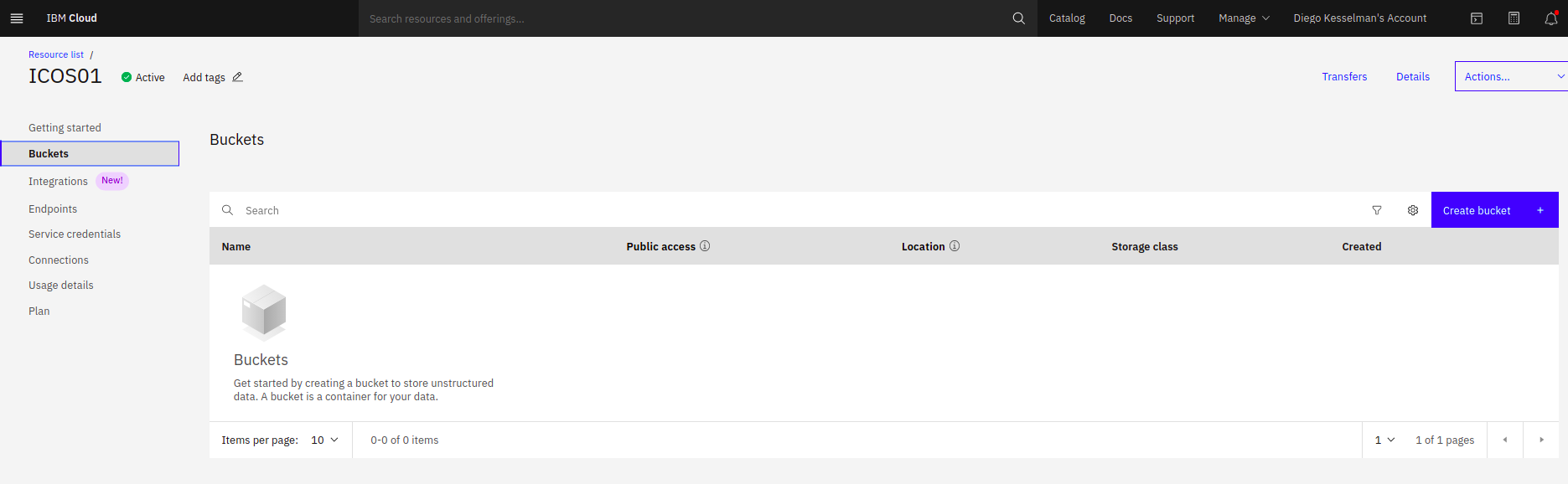
Figure 2-10 Select Bucket and Create the bucket
Figure 2-11 Create your bucket

Figure 2-12 Select bucket configuration - Smart Tier is the easy way

Figure 2-13 The endpoint option shows URLs
22. Take note of the endpoint URI. When connecting by using VPN, select Private. When connecting the internet, use Public (see Figure 2-14, Figure 2-15, Figure 2-16, and Figure 2-17 on page 30).

Figure 2-14 Service Credentials - Create Credential

Figure 2-15 Create Credential - Advanced Option - Include HMAC Credential

Figure 2-16 List new credential

Figure 2-17 Expand credential details
Take note of the Access Key and the Secret Key.
23. Return to Linux:
aws configure
– Use your credentials to log in.
– For this example, the region is eu-gb and the default output format is None.
24. Start compressing and uploading the image files. To avoid the use of more disk space, compress the files as they are being uploaded, as shown in Example 2-7.
Example 2-7 Compressing and uploading image files
cd /NFS/IBMi04
cat IMAGE01.ISO | pigz -9 -p40 -c | aws --endpoint-url=https://s3.eu-gb.cloud-object-storage.appdomain.cloud s3 cp - s3://ibmi-backup/IMAGE01.ISO.gz
cat IMAGE02.ISO | pigz -9 -p40 -c | aws --endpoint-url=https://s3.eu-gb.cloud-object-storage.appdomain.cloud s3 cp - s3://ibmi-backup/IMAGE02.ISO.gz
cat IMAGE03.ISO | pigz -9 -p40 -c | aws --endpoint-url=https://s3.eu-gb.cloud-object-storage.appdomain.cloud s3 cp - s3://ibmi-backup/IMAGE03.ISO.gz
cat IMAGE04.ISO | pigz -9 -p40 -c | aws --endpoint-url=https://s3.eu-gb.cloud-object-storage.appdomain.cloud s3 cp - s3://ibmi-backup/IMAGE04.ISO.gz
25. After the process completes, verify whether all files were uploaded to the Cloud Object Storage portal, as shown in Figure 2-18.

Figure 2-18 View objects in bucket
Example 2-8 Another way using Linux commands
aws --endpoint-url=https://s3.eu-gb.cloud-object-storage.appdomain.cloud s3 ls s3://ibmi-backup/
27. Return to the IBM Cloud Power Virtual Server environment.
28. Prepare the NFS server and the target system, both running IBM i.
29. The following requirements must be met to perform a full system restore because the system must be restart from the “A” or “B” side (not “D” IPL) and point to an NFS server to load the LIC:
– One TEMPORARY NFS instance is available to serve the images that are running IBM i V7R2, V7R3 or V7R4.
– The latest PTFs are on the TEMPORARY NFS instance.
– Enough disk space is available on the TEMPORARY NFS instance
– The target IBM i system is on the same network that is connected to the TEMPORARY NFS instance with enough resources to restore the backup. Open a Support ticket to enable the VLAN and connect the systems.
– Communications are in place from the TEMPORARY NFS instance to the IBM Cloud Object Storage or the place data was save. Consider the following points:
• This process can be done by using a Direct Link Connect and a reverse proxy. For more information, see this IBM Systems Lab Services Tutorial.
• The backups also can be downloaded by using the internet and the public access on IBM Cloud Object Storage. however, charges might be incurred on a public egress.
Restore process
Complete the following steps to restore the instance:
1. On the TEMPORARY NFS instance update YUM, as shown in Example 2-9.
Example 2-9 Updating YUM on PASE
CALL QP2TERM
/QOpenSys/pkgs/bin/yum -y update
2. Install some tools by using the ACS or command line, as shown in Example 2-10:
pigz gzip gunzip python3 python3-pip
Example 2-10 Install other tools from Access Client solutions
CALL QP2TERM
PATH=$PATH:/QOpenSys/pkgs/bin
export PATH
yum -y install pigz gzip gunzip python3 python3-pip
pip3 install s3cmd
pip3 install awscli
# Then you can configure awscli
aws configure
# Paste our Secret Key, Access Key and select the region.
3. Download the compressed images, as shown in Example 2-11.
Example 2-11 Downloading compressed image files
CALL QP2TERM
mkdir /NFS
mkdir /NFS/RESTORE21
chmod 755 /NFS
chmod 777 /NFS/RESTORE21
aws --endpoint-url=https://s3.eu-gb.cloud-object-storage.appdomain.cloud s3 cp s3://ibmi-backup/IMAGE01.ISO.gz /NFS/RESTORE21
aws --endpoint-url=https://s3.eu-gb.cloud-object-storage.appdomain.cloud s3 cp s3://ibmi-backup/IMAGE02.ISO.gz /NFS/RESTORE21
aws --endpoint-url=https://s3.eu-gb.cloud-object-storage.appdomain.cloud s3 cp s3://ibmi-backup/IMAGE03.ISO.gz /NFS/RESTORE21
aws --endpoint-url=https://s3.eu-gb.cloud-object-storage.appdomain.cloud s3 cp s3://ibmi-backup/IMAGE04.ISO.gz /NFS/RESTORE21
4. Decompress the images, as shown in Example 2-12.
Example 2-12 Decompressing image files
/QOpenSys/pkgs/bin/gunzip /NFS/RESTORE21/IMAGE01.ISO.gz
/QOpenSys/pkgs/bin/gunzip /NFS/RESTORE21/IMAGE02.ISO.gz
/QOpenSys/pkgs/bin/gunzip /NFS/RESTORE21/IMAGE03.ISO.gz
/QOpenSys/pkgs/bin/gunzip /NFS/RESTORE21/IMAGE04.ISO.gz
5. Press F3. Complete the following steps in QCMD:
a. Create an Image Catalog and add our virtual media:
CRTIMGCLG IMGCLG(RESTORE21) DIR('/NFS/RESTORE21') CRTDIR(*NO) ADDVRTVOL(*DIR) IMGTYPE(*ISO)
b. Create and male available a Virtual Optical Device:
CRTDEVOPT DEVD(NFSOPT) RSRCNAME(*VRT) LCLINTNETA(*N) VRYCFG CFGOBJ(NFSOPT) CFGTYPE(*DEV) STATUS(*ON)
c. Load the Image Catalog with the device:
LODIMGCLG IMGCLG(RESTORE21) DEV(NFSOPT)
d. Verify the IMAGE Catalog (some files are extracted for the remote IPL process):
VFYIMGCLG IMGCLG(RESTORE21) TYPE(*LIC) SORT(*YES) NFSSHR(*YES)
e. Change authorities:
CHGAUT OBJ('/NFS/RESTORE21') USER(*PUBLIC) DTAAUT(*RWX) SUBTREE(*ALL)
CHGAUT OBJ('/NFS/RESTORE21') USER(QTFTP) DTAAUT(*RX) SUBTREE(*ALL)
f. Export NFS Share as read-only:
CHGNFSEXP OPTIONS('-i -o ro') DIR('/NFS/RESTORE21')
g. Start NFS servers:
STRNFSSVR *ALL
h. Change the TFTP server attributes:
CHGTFTPA AUTOSTART(*YES) ALTSRCDIR('/NFS/RESTORE21')
i. Restart the TFTP server:
ENDTCPSVR SERVER(*TFTP)
STRTCPSVR SERVER(*TFTP)
6. Complete the following steps to set up the environment In the TARGET instance:
a. Configure Service Tools Server LAN Adapter by using a different IP address on the same private network segment and adapter (IP address is 192.168.80.21). Use the guidelines that were described in the previous backup process.
b. Add the NFS instance to the host table:
ADDTCPHTE INTNETADR('192.168.80.12') HOSTNAME((IBMiNFS))
c. Mount NFS SHARE on the target instance to confirm whether the files are visible:
MOUNT TYPE(*NFS) MFS('192.168.80.12:/NFS') MNTOVRDIR('/NFS')
WRKLNK '/NFS/RESTORE21/*'
d. Create the virtual optical device:
CRTDEVOPT DEVD(NFSRESTORE) RSRCNAME(*VRT) LCLINTNETA(*SRVLAN) RMTINTNETA('192.168.80.12') NETIMGDIR('/NFS/RESTORE21')
VRYCFG CFGOBJ(NFSRESTORE) CFGTYPE(*DEV) STATUS(*ON)
e. IPL the instance so that the changes can take effect.
f. Write the following information in your notes (see Figure 2-19, Figure 2-20, and Figure 2-21 on page 35):
• TCP/IP information: IP Address, Gateway, and Hostnames

Figure 2-19 Get IP address and associated line description

Figure 2-20 Display line description details and get the Resource Name
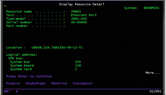
Figure 2-21 Display Resource Detail by using WRKHDWRSC *CMN option 7
• License keys: backup licenses to a file and transfer to NFS server:
DSPLICKEY OUTPUT(*LICKEYFILE) LICKEYFILE(QGPL/LIC01)
CRTSAVG QGPL/LIC
SAVOBJ OBJ(LIC01) LIB(QGPL) DEV(*SAVF) SAVF(QGPL/LIC)
g. Transfer the license keys to the NFS instance.
h. Start the network installation (see Figure 2-22):
STRNETINS DEV(NFSRESTORE) OPTION(*LIC) KEYLCKMOD(*MANUAL)

Figure 2-22 STRNETINS command
i. Click Finish or confirm the command at TARGET and the IPL process starts (a connection must be established to the console for manual operation).
This process can take several minutes until the DST window is displayed.
j. From the DST window, complete the following steps to install the License Machine Code (SLIC):
i. On the Install License Internal Code Menu, choose Option 2, and confirm by pressing F10.
The process to initialize the load source disk begins.
ii. Select Install Operating System. In this example, select the installation device type Option 5 - Network device.

Figure 2-23 Confirm your NFS instance values and continue with F10
iv. Confirm the installation of the operating system and then, press Enter.
v. Select a language group from the Select a Language Group Menu, (in this example, 2924 is selected).
vi. If disks must be added, use the Add All Disk Units to the System menu. In our example, option 1 is selected: Keep the current disk configuration.
vii. The sign-on window opens. Log in by using the QSECOFR user profile. The IPL options are displayed. Enter your choice (see Figure 2-24).

Figure 2-24 Set IPL Options as shown in this image.
viii. Set the Major System Options:
- Enable automatic configuration = Yes
- Device configuration naming = *NORMAL
- Default special environment = *NONE
- Device configuration naming = *NORMAL
- Default special environment = *NONE
The IBM i Installation status progress is displayed.
ix. After the operating system installation, you are ready to sign on; however, the password must be changed to continue the sign-on request.
7. Continue with setup and restore process:
a. Check resource name for your network adapter:
WRKHDWRSC *CMN
b. If the adapters changed, delete them and then, re-create them by using the correct resource:
CRTLINETH LIND(ETH01) RSRCNAME(CMN03)
CRTLINETH LIND(ETH02 RSRCNAME(CMN04)
c. Create Virtual Optical Device on Service Tool Server LAN Adapter (CMN04) again:
CRTDEVOPT DEVD(NFSRESTORE) RSRCNAME(*VRT) LCLINTNETA(*SRVLAN) RMTINTNETA('192.168.80.12') NETIMGDIR('/NFS/RESTORE21')
d. Vary on the Virtual Optical:
VRYCFG CFGOBJ(NFSRESTORE) CFGTYPE(*DEV) STATUS(*ON)
e. Check the NFS Image Catalog:
WRKIMGCLGE IMGCLG(*DEV) DEV(NFSRESTORE)
f. Continue with the restore process:
GO RESTORE
Option 21
g. Use NFSRESTORE as device name.
8. After the restore process completes, complete the following steps to check the messages and system:
a. Check the software products:
GO LICPGM
Option 10
b. Change system values to fit the new environment:
WRKSYSVAL
c. Change the network name:
CHGNETA SYSNAME(IBMI04) LCLCPNAME(IBMI04) LCLLOCNAME(IBMI04) DTACPR(*ALLOW) DTACPRINM(*REQUEST) NETSERVER((IBMI04 *ANY)) NWSDOMAIN(IBMI04) ALWVRTAPPN(*YES) ALWHPRTWR(*YES)
d. Change the network configuration by using the previously saved values:
CFGTCP
e. On the NFS instance, start the FTP service (it is down by default):
STRTCPSVR *FTP
f. Restore the license keys, as shown in Example 2-13.
Example 2-13 Restoring licensing keys
#From 5250 terminal
CRTSAVF QGPL/LIC
#From PASE
FTP ‘192.168.80.12’
bin
cd QGPL
get LIC (REPLA
quit
# From 5250 terminal
RSTOBJ OBJ(*ALL) SAVLIB(QGPL) DEV(*SAVF) SAVF(QGPL/LIC)
ADDLICKEY LICKEYINP(*LICKEYFILE) LICKEYFILE(QGPL/LIC01)
g. Validate license keys:
DSPLICKEY
h. Change the IPL mode to NORMAL from IBM Cloud Power Virtual Server portal.
i. Restart the TARGET instance:
PWRDWNSYS *IMMED RESTART(*YES) CONFIRM(*NO)
Now, the IBM i TARGET system is running and the validation process can begin.
|
Alert: If a failure occurs during the LIC or operating system installation process, delete the instance and start again by installing the LIC and operating system.
|
2.2.3 Full-system backup from IBM i Source by using BRMS and IBM Cloud Storage and Restore on IBM Power Systems Virtual Server
This section describes how to perform a save and transfer of an IBM i workload on-premises to Power Systems Virtual Server by using Backup, Recovery, and Media Services (BRMS) with the IBM Cloud Storage licensed program product (LPP) for IBM i.
We continue showing how to restore the previously saved IBM i workload in the Power Systems Virtual Server environment.
Solution components and requirements
This section describes the solutions components and requirements.
Required components on the IBM i Local Source LPAR/VM
The following components must be set up on the IBM i Local Source:
•BRMS and IBM Cloud Storage software
•IBM i System Minimum PTF levels
•BRMS and IBM Cloud Storage PTFs
•Cloud-Init for IBM i and PTFs
•System is saved by using BRMS/IBM Cloud Storage to IBM Cloud Object Storage
•BRMS Recovery Reports are created
IBM i Source system requirements
The BRMS and IBM Cloud Storage software must be installed. Complete the following steps:
1. Install the following operating system options and BRMS:
– 5770-SS1Option 18: Media and Storage Extensions
– 5770-SS1Option 44: Encrypted Backup Enablement (optional)
– 5770-BR1*BASE
– 5770-BR1Option 1: Network feature (optional)
– 5770-BR1Option 2: Advanced Functions feature (optional)
2. Install IBM Cloud Storage Solutions:
– 5733ICC *BASE IBM Cloud Storage Solutions for i
– 5733ICC Option 1: Cloud Storage
– 5733ICC Option 2: Advanced
– 5733ICC Option 3: Reserved – Option 3
– 5733ICC Option 4: Reserved – Option 4
– 5733ICC Option 5: Reserved – Option 5
– 5733ICC Option 6: Reserved – Option 6
– 5733ICC Option 7: Reserved – Option 7
IBM i Source System PTF minimum levels
The following program temporary fixes (PTFs) must be installed on your IBM i VM:
•PTFs for IBM i License Keys Post Deployment
•License Keys that are incorporated as part of the deployment of the LPAR.
•License Keys can take 5 minutes to appear post deployment:
– IBM i 7.2 - 5770SS1 SI71091 (prerequisite SLIC PTFs: MF66395, MF66394, MF66391)
– IBM i 7.3 - MF99207 (TR7) and SI69686
– IBM i 7.4 - MF99301 (TR1) and SI70544
For information about the minimum required software levels, see this IBM Cloud Docs web page.
•The following BRMS PTFs must be installed on a stand-alone BRMS system or on all of the systems in a BRMS network:
– 7.3 - SI61153
– 7.2 - SI61152
– 7.1 - SI61151
•The SI73401 - Cloud Storage Solutions Proxy Support 5733ICC IBM Cloud Storage Solutions for i PTF must be installed for Direct Link (DL) Reverse Proxy Server Support. Support Google Cloud Storage.
IBM i software requirements
For Cloud-Init Support for IBM i, this Cloud-Init requirement is installed post deployment. Any images that are imported to the cloud must have cloud-init installed.
If you are bringing your own IBM i custom SAVSYS, you must install these SAVSYS PTFs and the software that is required for cloud-init. For more information, see this IBM Support web page.
Installing cloud-init on IBM i
Specific LPPs and PTFs are needed for IBM i so that cloud-init can work. Complete the following steps to install and configure cloud-init on IBM i:
1. Download and install the required license programs:
– 5770DG1 with *ALL
– 5770SS1 with Option 30 and 33
– 5770SC1 *BASE and option 1
2. Install following rpm packages:
– python2-ibm_db-2.0.5.8
– python2-six-1.10.0-1
– python2-2.7.15-1
– cloud-init-1.2-100
|
Note: Consider the following points:
•The listed version of rpm packages is the required lowest version.
•The rpm packages can be installed by using yum. For more information, see this web page.
|
3. Install the following required PTFs and PTF groups:
– 7.2: SF99713, MF61899 (permanently apply), SI62642, SI63163, MF65261, MF65218, and SI72162
– 7.3: MF61942 (permanently apply), SI62642, SI63041, MF63830, and SI72161
– 7.4: SI72142
4. Save and migrate your system.
|
Note: For IBM i 7.2 and 7.3 on POWER8® and later version, cloud-init is enabled automatically.
For IBM i 7.2 and 7.3 or other IBM i versions that are running on POWER7 or later Power Systems servers, the process that is described in “Installing cloud-init on IBM i” on page 40 must be completed to run cloud-init on IBM i.
|
Enabling cloud-init on IBM i
To enable the cloud-init on an IBM i machine manually, run this on the virtual machine, as shown in Example 2-14.
Example 2-14 Enable cloud-init on IBM i
CALL PGM(QSYS/QAENGCHG) PARM(*ENABLECI)
This command must be run with a user profile that includes the following access privileges:
•*ALLOBJ
•*AUDIT
•*IOSYSCFG
•*JOBCTL
•*SAVSYS
•*SECADM
•*SERVICE
•*SPLCTL
After you enable cloud-init on the IBM i server, power off the system; then, it is ready to save and migrate.
Downloading the required software
Complete the following steps to download the required software (for more information, see this IBM Support web page):

Figure 2-25 Entitled Systems Support (ESS) portal
2. The entitled software downloads are shown in Figure 2-26. Click IBM i evaluation. For more information, see hthis web page.

Figure 2-26 Software downloads option
3. Select a category and group, as shown in Figure 2-27.

Figure 2-27 Selecting IBM i and release category

Figure 2-28 Selecting 5770-SS1

Figure 2-29 Entitled software downloads - Select language and press Continue

Figure 2-30 Selecting package for download
7. Save and download the IBM_Cloud_Storage_Solutions_for_i_LCD8_2390_02_udt.zip, as shown in Figure 2-31.

Figure 2-31 Downloading IBM Cloud Storage Solutions for i using HTTP
In our system, we extracted the compressed file content and renamed it to 5733ICC.udf.
Preparing an optical image catalog to install software
In this section, we describe how to create an image catalog and an image catalog entry, add an image catalog entry, and load the image catalog in preparation of performing an IBM i software upgrade. The steps use a virtual optical device in the example. The server setup requires an image catalog setup that is then shared with the client partition.
Complete the following steps:
1. Create a virtual optical device.
To create a device description, enter the command that is shown in Example 2-15.
Example 2-15 Create a device description
CRTDEVOPT DEVD(virtual-device-name) RSRCNAME(*VRT)+
ONLINE(*YES) TEXT(text-description)
2. Vary on the virtual optical device, as shown in Example 2-16.
Example 2-16 Vary on the Virtual Optical Device
VRYCFG CFGOBJ(virtual-device-name) CFGTYPE(*DEV) STATUS(*ON)
3. Create an image catalog for the licensed programs that you want to install. The Create Image Catalog (CRTIMGCLG) command associates an image catalog with a target directory where the optical image files are loaded, as shown in Example 2-17.
Example 2-17 Create image catalog
CRTIMGCLG IMGCLG(catalog-name) DIR(catalog-path) CRTDIR(*YES) TEXT(text-description)
4. If you downloaded your images into an image catalog directory, two quick methods are available to add all of the images at once into your image catalog:
Example 2-18 Create Image Catalog and add volumes
CRTIMGCLG IMGCLG(catalog-name) DIR(catalog-path) ADDVRTVOL(*DIR) IMGTYPE(*ALL) TEXT(text-description)
– Use the QVOIFIMG API when the image catalog already exists as shown in Example 2-19.
Example 2-19 Add images to an existing image catalog with QVOIFIMG
CALL PGM(QVOIFIMG) PARM('catalog-name' '*ALL' 0)
5. Add an image catalog entry for each physical media or optical image file. You must repeat this step for each volume of media. Add the physical media or optical image files in the same order as though you were going to install from them. Start with the first media in the list and continue until all of the media are loaded.
You can add the entries from an optical device or from an optical image file. Select one of the following methods:
– From an image file
This method is the fastest way. To add an image entry to an image catalog from an Integrated File System file that is in the image catalog directory, enter the command as shown in Example 2-20.
Example 2-20 Add image entry to an image catalog
ADDIMGCLGE IMGCLG(catalog-name) FROMFILE(file-name) TOFILE(*fromfile) TEXT(text-description)
|
Note: If you need to add multiple images, see the CRTIMGCLG command and the QVOIFIMG API to add all of the images at the same time.
|
– To add an image catalog entry to an image catalog from an integrated file system optical image file that is from a directory other than the image catalog directory, enter the commands as shown in Example 2-21.
Example 2-21 Add image catalog entry from optical image
ADDIMGCLGE IMGCLG(catalog-name) FROMFILE(/directory-name/directory-name/file-name) TOFILE(file-name or *FROMFILE) TEXT(text-description)
– From a physical device
Add an image catalog entry to an image catalog from a physical optical media by using the optical device that is named OPT01, as shown in Example 2-22.
Example 2-22 Add Image Catalog Entry from a physical device
ADDIMGCLGE IMGCLG(catalog-name) FROMDEV(OPT01) TOFILE(file-name or *GEN) TEXT(text-description)
|
Note: To generate a name for the TOFILE parameter and a text description from the media, specify *GEN.
|
6. Load the image catalog.
This step associates the virtual optical device to the image catalog. Only one image catalog at a time can be associated with a specific virtual optical device. To load the image catalog, run the command as shown in Example 2-23.
Example 2-23 Load the Virtual Optical Device to the Image Catalog
LODIMGCLG IMGCLG(catalog-name) DEV(virtual-device-name) OPTION(*LOAD)
7. Verify that the images are in the correct order.
|
Note: If you are preselecting the licensed programs to install, do not perform this step now. You are directed to perform this step later.
|
If you are preparing for an upgrade, you must verify that the required media for an upgrade exists and is sorted in the correct sequence. You also must verify that your software agreements were accepted, and that reserved storage is available for the Licensed Internal Code.
Enter the command as shown in Example 2-24.
Example 2-24 Verify image catalog
VFYIMGCLG IMGCLG(catalog-name) TYPE(*UPGRADE) SORT(*YES)
To verify that images are added, another method, as shown in Example 2-25.
Example 2-25 Work with Image Catalog
WRKIMGCLGE IMGCLG(catalog-name)
Then, press F7 to prompt for the VFYIMGCLG command. Enter *UPGRADE for the type and *YES for the sort field.
The system puts the images in the correct order. (If you are not successful, refer to Image catalog recovery.) By default, the volume with the lowest index is mounted. Then, all other volumes are loaded.
To see the order of the images, use the Work with Image Catalog Entries (WRKIMGCLGE) command:
WRKIMGCLGE IMGCLG(catalog-name)
After completing these steps, your image catalog is ready for use.
Required components in the IBM Cloud
The following components must be set up in the IBM Cloud UI:
•An IBM Cloud account (beyond the scope of this document).
•Create a Power Systems Virtual Server service and a private subnet.
•Provision IBM i.
•Virtual Server Instances (VSIs).
•Order Direct Link Connect Classic to connect each Power Systems Virtual Server location to IBM Cloud Classic, which is required for IBM Cloud Object Storage access for saves and restores.
•Create and configure a Reverse-proxy CentOS VSI to connect each Power Systems Virtual Server location to IBM Cloud Classic. For more information, see this IBM Documentation web page.
Full-system backups from IBM i source by using BRMS and IBM Cloud Storage
The following save data must be restored from physical media before BRMS can begin restoring save data directly from the cloud:
•SAVSYS to install the operating system.
•IBM Backup, Recovery, and Media Services for i and BRMS save information.
•IBM TCP/IP Connectivity for i and configuration information to allow communications with cloud storage providers.
•IBM Cloud Storage Solutions for i and configuration information to establish connections with cloud storage providers.
•BRMS provides specific control groups that can be used to automatically save this data to media in the cloud and the cloud media can be used to create physical media. The control groups create cloud media that is formatted so it can be downloaded and burned directly to physical optical media. All remaining data on the system can be backed up to media in the cloud and restored directly from the cloud without a need to create physical media.
•Control group QCLDBIPLnn can be used to perform full backups of all data that must be recovered from physical media. Likewise, QCLDBGRPnn can be used to perform cumulative incremental saves of the data that must be recovered from physical media.
|
Note: The Journaled objects control group field must be changed to *YES for a QCLDBGRPnn control group before the control group is used to perform an incremental backup.
Run the WRKCTLGBRM command and change the Journaled objects field by specifying option 8=Change attributes for QCLDBGRPnn.
|
•Control group QCLDBSYSnn can be used to perform a full backup of the data that can be restored directly from the cloud. Likewise, control group QCLDBUSRnn can be used to perform cumulative incremental backups of the data that can be restored directly from the cloud.
|
Note: The Journaled objects control group field must be changed to *YES for a QCLDBGRPnn control group before the control group is used to perform an incremental backup.
Run the WRKCTLGBRM command and change the Journaled objects field by specifying option 8=Change attributes for QCLDBGRPnn.
|
It is critical to run the cloud control groups in the correct order; otherwise, all necessary media information is not available to perform a recovery.
2.2.4 Solution diagrams
This section provides more information about the solution scenarios that are presented in this chapter.
Migrating IBM i to the Cloud using IBM Cloud Object Storage
This section shows a migration of IBM i to the cloud by using IBM Cloud Object Storage. Refer to Figure 2-32.
Consider the following points about migrating IBM i into IBM Cloud Object Storage (see Example 2-32 on page 53):
•Use 5733-ICC and BRMS to transfer VM to IBM Cloud Object Storage.
•Requires 2x disk space on-premises.
•Requires reasonable network connection to IBM Cloud.
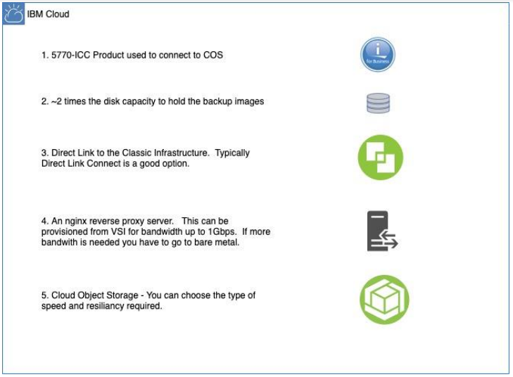
Figure 2-32 Migrating IBM i to the Cloud using IBM Cloud Object Storage
Example 2-26 Run BRMS Control Group QCLDBSYS01
STRBKUBRM CTLGRP(QCLDBSYS01) SBMJOB(*NO)
Example 2-27 Run BRMS Control Group QCLDBIPL01
STRBKUBRM CTLGRP(QCLDBIPL01) SBMJOB(*NO)
Figure 2-33 shows the steps to retrieve your image by using IBM Cloud Storage Solutions
for i.
for i.

Figure 2-33 Get your BRMS Image Catalog on IBM Cloud Object Storage
Running a full-system backup from the console
In this example, you run a restricted state backup by using your HMC or LAN Console connection.
Complete the following steps to perform a full save of your entire system:
|
Note: Processing time for each backup depends on the size of your system processor, device capability, and the amount of data that you want to save.
You cannot perform other activities during these backups because your system is in a restricted state.
|
1. Run the BRMS Control Group QCLDBSYS01.
2. Put the system in restricted state as shown in Example 2-28 on page 51.
Example 2-28 Put the system in restricted state
ENDSBS SBS(*ALL) DELAY(120)
3. Display QSYSOPR MSGQ, run the DSPMSG QSECOFR command, and look for the following messages:
– System ended to restricted condition.
– A request to end TCP/IP has completed.
4. Change subsystems to process for Control Group QCLDBSYS01:
a. Run the WRKCTLGBRM command.
c. Select Option 9=Subsystems to process.
d. Change Restart to *NO for Seq 10 Subsystem *ALL.
|
Note: If you see a break message during the backup, press Enter to return you to the window in which you entered the STRBKUBRM command so that you can review the backup progress.
|

Figure 2-34 WRKCTLGBRM - Find QCLDBSYS01
5. Run the First backup from the console, as shown in Figure 2-29 on page 44.
Example 2-29 Run first backup from console
STRBKUBRM CTLGRP(QCLDBSYS01) SBMJOB(*NO)
6. Check the backup for errors. It is normal to see some errors, such as the following examples:
– Objects not saved (some objects are not required for the recovery).
– Media not transferred (complete this step manually after the second backup).
7. Check the subsystems after the backup completes. You see only subsystem QCTL in a status of RSTD. If not, end all subsystems again, as shown in Example 2-30.
Example 2-30 End all Subsystems again when QCTL is not the only one running
ENDSBS SBS(*ALL) DELAY(120)
8. Change BRMS Control Group QCLDBIPL01:
a. Use the WRKCTLGBRM command.
b. Select Option 8=Change attributes.
c. Page down, change Automatically backup media information to *LIB, also Append to media to *NO.
d. Select Option 9=Subsystems to process.
e. Change Restart to *YES for Seq 10 Subsystem *ALL.
|
Note: Control groups that have a QCLD prefix enable BRMS to automatically create and transfer media to the cloud. Control groups QCLDBIPLxx or QCLDBGRPxx must be used to burn DVDs for recovery. If the backup uses media class QCLDVRTOPT, the BRMS default is to create 10 virtual volumes to back up to optical.
|
– Because optical devices do not have an exit program interface to handle media switching while a backup is running, the backup command must provide enough volumes to successfully hold the backup data. A symptom that indicates the backup does not fit on the initial number of volumes that are provided is that the backup fails with message BRM4301 Volume list exhausted.
– When control groups QCLDBIPLxx or QCLDGRPxx are used, the required volume size is 4.7 GB to burn DVDs for manual recovery. The control group data size cannot exceed 350 GB because of the 75 volume restriction.
9. Set the number of optical volumes for automatic transfers:
– The number of virtual optical volumes to create can be specified by running the command that is shown in Example 2-31.
Example 2-31 Set number of Optical Volumes for Automatic Transfer
CALL PGM(QBRM/Q1AOLD) PARM('NUMOPTVOLS' '*SET ' 'nn')
– nn is the number of volumes to auto create. This value must be 1 - 75.
– The number of volumes to create can be displayed by running the command that is shown in Example 2-32.
Example 2-32 Display the number of volumes to create
CALL PGM(QBRM/Q1AOLD) PARM('NUMOPTVOLS' '*DISPLAY')
– The number of volumes to create can be reset to the default value of 10 by running the command that is shown in Example 2-33.
Example 2-33 Reset the number of volumes
CALL PGM(QBRM/Q1AOLD) PARM('NUMOPTVOLS' '*REMOVE')
– Run the second backup from the console, as shown in Example 2-34.
Example 2-34 Run the second backup
STRBKUBRM CTLGRP(QCLDBIPL01) SBMJOB(*NO)
– Check the backup for errors. It is normal to see some errors, such as the following examples:
• Objects not saved (some objects are not required for the recovery).
• Media not transferred (complete manually after the second backup).
– Identify the volumes that are used for backups QCLDBSYS01 and QCLDBIPL001 and transfer to IBM Cloud Object Storage.
– Check the status of the transfer by running the WRKSTSICC STATUS(*ALL) command.
– If the status is Failed, this status is normal. The volumes are transferred in the next step.
– Identify which volumes were used for the backups, as shown in Example 2-35.
Example 2-35 Identify volumes transferred
WRKMEDBRM TYPE(*TRF)
10. Transfer the volumes to IBM Cloud Object Storage.
Use the commands that are shown in Example 2-36 to transfer the volumes to IBM Cloud Object Storage.
Example 2-36 Transfer volumes to IBM Cloud Object Storage
STRMNTBRM
WRKSTSICC STATUS(*ALL)
The volume name, status, and complete percentage for each file transfer is shown. Wait until all volumes are successfully completed to proceed to the next step.
11. Verify that all of the volumes that were used for the full-system backup no longer have a status of *TRF, as shown in Example 2-37.
Example 2-37 Identify volumes transferred
WRKMEDBRM TYPE(*TRF)
You do not see any Volumes in the list.
12. As with other recoveries that are performed by using BRMS, a recovery report is used to assist with successful recoveries from save media that was transferred to the cloud. To generate a report for recovery from the cloud, run the command that is shown in Example 2-38.
Example 2-38 Generate BRMS recovery report from the cloud
STRRCYBRM OPTION(*CTLGRP) ACTION(*REPORT) CTLGRP((QCLDBSYS01 1) (QCLDBIPL01 2))
|
Note: It is important to review the recovery report to ensure it is complete. If any of the media that is produced during the backup process is not successfully transferred to the cloud, it is not included in the recovery report.
The CTLGRP and PERIOD parameters that are specified with the STRRCYBRM command help identify objects that are saved to volumes that were not transferred to the cloud.
If objects are on volumes that were not included in the recovery report, they are listed in a Missing Objects Attention section near the top of the report.
|
After the recovery report is verified, the report is stored in a safe location so it can be referred to during a recovery.
13. Daily incremental backups can be run Monday - Saturday by using the control groups command, as shown in Example 2-39.
Example 2-39 BRMS - Run daily incremental backups
STRBKUBRM CTLGRP(QCLDBUSR01) SBMJOB(*NO)
STRBKUBRM CTLGRP(QCLDBGRP01) SBMJOB(*NO)
Full-system recovery from the Cloud by using IBM i as NFS server
This section describes how to recover a system from the cloud by using IBM i as the NFS server.
Setting up IBM i network installation server with NFS Server and NFS Client
Complete the following steps to set up IBM i network installation server with NFS server and NFS client:
1. Provision an IBM i VSI in the target Power Systems Virtual Server location to be an NFS Server.
IBM i NFS Server is at a minimum on Version 7.2 with current PTFs.
2. To use virtual optical images through an NFS server, the IBM i NFS client must meet the following requirements:
– The IBM i includes a Version 4 Internet Protocol (IP) address.
– During set-up, the shared NFS server directory is mounted over a directory on the IBM i client.
– An IBM i service tools server or a LAN console connection is configured by using a Version 4 IP address.
– A 632B-003 virtual optical device is created that uses the IP address of the NFS server.
|
Note: The IBM i IP address and the IBM i service tools server (LAN console connection) IP address can be the same.
|
In this section, we described how to recover from NFS. For more information, see 4.2.8, “Full-system recovery from the cloud using IBM i as an NFS server” on page 94.
2.2.5 Migrating IBM i by using PowerVC to PowerVS
IBM PowerVC is an advanced virtualization and cloud management offering that is built on OpenStack. It provides simplified virtualization management and cloud deployments for IBM i VMs that are running on IBM Power Systems.
It also provides numerous operational benefits, such as one-click system evacuation for simplified server maintenance, dynamic resource optimization (DRO) to balance server usage during peak times, and automated VM restart to recover from failures.
Users can easily import and export VM images (in the standard Open Virtual Application (.OVA) format) from IBM PowerVC and upload them into IBM Cloud for easy back-and-forth image mobility.
For more information about migrating an IBM i VM from IBM Power Virtualization Center to IBM Power Systems Virtual Server, see Red Hat OpenShift V4.X and IBM Cloud Pak on IBM Power Systems Volume 2, SG24-8486.
IBM Cloud Pak for multicloud management
IBM Cloud Pak® for Multicloud Management provides consistent visibility, governance, and automation across many platforms. Whether you are considering managing VMs, containers, public clouds, or an on-premises infrastructure, IBM Cloud Pak for Multicloud Management features the tools to ensure that your enterprise runs smoothly. IBM Cloud Pak for Multicloud Management includes Infrastructure management and Service management components.
Infrastructure management delivers the insight, control, and automation enterprises that are need to address the challenges of managing virtual environments, which are far more complex than physical environments.
Consider the following points:
•The Infrastructure management module was called IBM Red Hat CloudForms.
•The Managed services module was called Terraform and Service Automation or IBM Cloud Automation Manager.
The use of IBM Cloud Pak for Multicloud Management can be an end-to-end solution to manage IBM i workloads on- and off-premises. Therefore, you can migrate and deploy IBM i images, as shown in Figure 2-35.

Figure 2-35 Export IBM i PowerVC images to IBM PowerVS
|
Tip: IBM i images can be deployed on- or off-premises by using Infrastructure-as-Code (IaC) that uses HarshiCorp Terraform. You also can use Ansible for i for deployment and configuration management. This approach can be used for deploying an IBM i image by Terraform and configuration management that uses Ansible controller on IBM i as an in-house setup.
For an Enterprise solution, the use of IBM Cloud Pak for Multicloud Management that is integrated with Terraform, Red Hat Ansible Automation Platform, and Ansible Tower (compatible with IBM i systems), can be a solution for IBM i workloads management, and as a DevOps strategy on IBM i, including application deployment, reduce delivery cycles, and so forth. A hybrid cloud approach also is committed for IBM i systems.
|
2.2.6 Migrating IBM i by using Mass Data Migration
Mass Data Migration is a fast, simple, secure way to physically transfer terabytes to petabytes of data to or from IBM Cloud. Whether it is to release on-premises storage space, decommission data centers, or pursue a gateway into IBM Cloud, Mass Data Migration is a versatile physical data transfer solution with which commercial- and enterprise-level customers in every industry can move large amounts of data to IBM Cloud quickly and securely.
|
Important: Online ordering is available in most regions, except Brazil and India. If the region you are in does not support online ordering, contact your IBM Client Representative to inquire about the use of the service. For more information and support, see this IBM Cloud Docs web page.
|
Features
Data migration includes the following features:
•120 TB usable capacity with RAID-6 configuration
•Inline AES 256-bit encryption
•Inline compression
•Ruggedized, tamper-evident, Trusted Platform Module (TPM)-enabled cases
•NIST data wipe standards upon completion
Pricing
Ordering a Mass Data Migration device does not include any up-front costs. Consider that your account accrues a daily usage charge of USD 50.00.
If you are importing data to IBM Cloud, the charges accrue after the device arrives at your location. If you are exporting data from IBM Cloud, the charges accrue when device is prepared for data copy. The charges stop accruing the day that the device is received by the IBM Cloud data center.
Also, after the data on your device is offloaded into your targeted IBM Cloud Object Storage bucket, your account accrues associated Cloud Object Storage costs. For more information about Mass Data Migration, see this IBM Technology YouTube video.
Migrating IBM i Data to IBM Cloud by using Mass Data Migration
This section describes an alternative method for performing the IBM i on-premises save and transfer of data to IBM Cloud Object Storage (see Figure 2-36).

Figure 2-36 IBM i data save on Mass Data Migration
|
Note: Restore in IBM Power Systems Virtual Server is performed by using an IBM i VM as an NFS server.
|
Using the Mass Data Migration device
IBM i data is migrated to the IBM Cloud by using an IBM Cloud Mass Data Migration device. The IBM i data is saved to virtual optical images in a Network File System (NFS) share that is on the Mass Data Migration device at your data center.
You then must send the Mass Data Migration device back to IBM where your data is moved to the IBM Cloud so that it can be accessed through your IBM Cloud Object Storage. the process includes the following steps:
1. The MDM device is mounted to IBM i IFS.
2. An NFS-backed Optical IMGCLG is created.
3. Save the image directly to the MDM device.
4. A transfer rates of ~100 - 120 MBps is observed.
5. The MDM device is sent back to IBM Cloud.
6. The device is uploaded into IBM Cloud Object Storage by IBM Cloud.
7. IBM i is restored from IBM Cloud Object Storage.
|
Important: For more information, see this IBM Cloud Docs web page.
The tutorial directs you to set up your IBM Cloud account for data migration and request a Mass Storage Migration device.
|
Preparing IBM Cloud Mass Data Migration device for IBM i data
After you receive the Mass Storage Migration device, review the IBM Cloud Docs web page and then, use the following checklist to complete the device set up:
|
Note: IBM Cloud Mass Data Migration devices arrive preconfigured and ready to connect to your network. For more information, see this IBM Cloud Docs web page.
|
•After you set up the IBM Cloud Mass Data Migration device for Ethernet connectivity, you can access the device user interface. For more information, see this IBM Cloud Docs web page.
•You can copy data onto the IBM Cloud Mass Data Migration device by first unlocking and activating the storage pool that is provisioned for the device. More information, see this IBM Cloud Docs web page.
•Review this IBM Cloud Docs web page topic to ensure that the shares are set up correctly for the IBM i. The directory (or a parent directory) that contains the virtual optical images must be shared with the following characteristics:
– The following Internet Protocol (IP) addresses:
• IBM i client.
• IBM i client service tools server or the LAN console connection if it is different than the system IP address. For more information, see this IBM Documentation web page.
– For read and write.
|
Note: The IBM i IP address and the IBM i service tools server (LAN console connection) IP address can be the same.
|
Preparing IBM i to use the Cloud Mass Data Migration device
The following requirements must be met to share virtual optical images with an IBM i client through an NFS server:
•The IBM i NFS client has a Version 4 IP address.
•The IBM i NFS client has the NFS server share mounted over a local directory during the setup process.
•The IBM i NFS client has a 632B-003 virtual optical device that uses the IP address of the NFS server.
•A directory under the NFS server share contains images that are large enough to hold all save data for the IBM i client.
|
Note: Save operations cannot dynamically create images or dynamically extend the size of images; therefore, understanding of the size of the data that is generated by the save operation is important.
|
•A directory under the NFS server share has a volume list file that contains a list of images to be used by an IBM i client. The volume list file must have the following characteristics:
– Its ID is in the same directory as the image files
– Is named VOLUME_LIST
– Contains ASCII characters
Consider the following points:
– Each entry in the file is an image file name with access intent or a comment.
– Image file names are limited to 127 characters.
– All characters following a hash symbol (#) are considered a comment and are ignored.
– The order of the image file names in the volume list file indicates the order the images are processed on the IBM i client.
Setting up the IBM i NFS client
Complete the following steps to set up the IBM i client to use virtual optical images that are stored on an NFS server. The following command examples assume that NFS server SERVER01 with an IP address '1.2.3.4' has share /nfs/share01:
1. Create a mount directory for the NFS server:
MKDIR DIR('/NFS')
MKDIR DIR('/NFS/SERVER01')
2. Mount the NFS server root directory over the IBM i mount directory:
MOUNT TYPE(*NFS) MFS('1.2.3.4:/nfs/share01') MNTOVRDIR('/NFS/SERVER01')
3. Create image information about the NFS server in the Portable Application Solutions Environment (PASE).
4. Create a device description for a virtual optical device:
CRTDEVOPT DEVD(NFSDEV01) RSRCNAME(*VRT) LCLINTNETA(*SRVLAN) RMTINTNETA('1.2.3.4') NETIMGDIR('/nfs/share01/iImages')
5. Vary on the virtual optical device:
|
Note: If the images or VOLUME_LIST file is changed on the NFS server, the virtual optical device must be varied off and then, varied back on to use the virtual images.
|
VRYCFG CFGOBJ(NFSDEV01) CFGTYPE(*DEV) STATUS(*ON)
6. Use the device to initialize the image files as optical volumes:
LODIMGCLGE IMGCLG(*DEV) IMGCLGIDX(3) DEV(NFSDEV01) INZOPT NEWVOL(IVOL03) DEV(NFSDEV01) CHECK(*NO)
LODIMGCLGE IMGCLG(*DEV) IMGCLGIDX(2) DEV(NFSDEV01) INZOPT NEWVOL(IVOL02) DEV(NFSDEV01) CHECK(*NO)
LODIMGCLGE IMGCLG(*DEV) IMGCLGIDX(1) DEV(NFSDEV01) INZOPT NEWVOL(IVOL01) DEV(NFSDEV01) CHECK(*NO)
7. Virtual device NFSDEV01 can now be used for native IBM i save and restore operations. Volume IVOL01 (image file '/nfs/share01/iImages/IMAGE01.ISO') is mounted on device NFSDEV01.
To test the device, perform the following command to verify that a message queue can be saved and restored. Messages from the save and restore commands indicate that one object was saved and one object was restored:
CRTMSGQ MSGQ(QTEMP/MSGQ) SAVOBJ OBJ(MSGQ) LIB(QTEMP) DEV(NFSDEV01) CLEAR(*ALL) RSTOBJ OBJ(*ALL) SAVLIB(QTEMP) DEV(NFSDEV01)
The save contents of the virtual optical volume can also be displayed:
DSPOPT VOL(IVOL01) DEV(NFSDEV01) DATA(*SAVRST) PATH(*ALL)
Saving IBM i data to the Cloud Mass Data Migration device
Perform an IBM i full-system save by using the instructions that are described in “Running a full-system backup from the console” on page 51. However, use the newly mounted NFS device (the MDM device) as a target instead of the local image catalog and IBM Cloud Storage.
Returning the Cloud Mass Data Migration device to IBM
To complete the migration of IBM i data to IBM Cloud, follow the process that is described at this IBM Cloud Docs web page.
..................Content has been hidden....................
You can't read the all page of ebook, please click here login for view all page.