

Using the GLVM Configuration Assistant
This chapter describes how to configure GLVM for PowerHA SystemMirror Enterprise Edition with the GLVM Cluster Configuration Assistant
SystemMirror with GLVM allows mission critical data to be replicated across different geographical sites. Geographic Logical Volume Manager (GLVM) provides the data replication over the IP networks for use in disaster recovery solutions and protects the data against total site failure by remote mirroring between the participating sites.
This chapter describes the following topics:
7.1 Choosing the data replication type
The Geographic Logical Volume Manager (GLVM) is based on the AIX Logical Volume Manager (LVM) and allows mirroring of data at geographically distant locations. There are two supported modes of mirroring with GLVM:
•Synchronous
•Asynchronous
7.1.1 Synchronous Mirroring
Synchronous mirroring writes to both the local and remote sites simultaneously, the downside of implementing this solution is that writes to the remote physical volumes can have an impact on the application response time. A possible Synchronous GLVM configuration is shown in Figure 7-1.
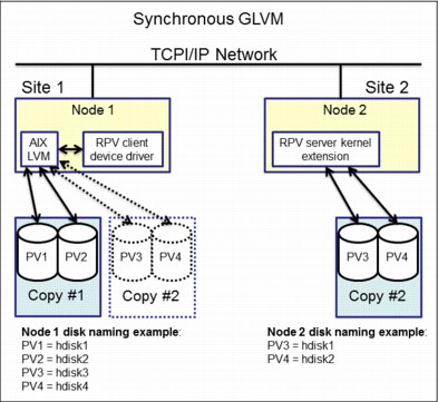
Figure 7-1 Synchronous GLVM
7.1.2 Asynchronous Mirroring
Asynchronous mirroring allows the local site to be updated immediately and the remote site to be updated as network bandwidth allows. Information is cached and sent later, as network resources become available. This can greatly increase application response time, but there is some risk of data loss.
Figure 7-2 on page 263 shows a configuration example for asynchronous GLVM.

Figure 7-2 Asynchronous GLVM using mirror pools
7.1.3 GLVM Configuration Assistant
With the GLVM Configuration Assistant you can create a Geographically Mirrored Volume Group (GMVG) with the following characteristics:
•The GMVG exists on all nodes in the cluster.
•All available persistent labels on XD_data networks are used.
•A resource group is created with the following attributes:
– Prefer Primary Site
– On Home Node Only
– Fallover To Next Priority Node In The List
– Never Fallback
7.2 Configuration requirements
Ensure that you meet the following requirements before configuring a GLVM environment using the GLVM Cluster Configuration Assistant:
•A cluster is configured with sites.
•A repository disk is defined in the cluster configuration.
•The verification and synchronization process completes successfully on the cluster.
•XD_data networks with persistent IP labels are defined on the cluster.
•The network communication between the local site and remote site is working.
•All PowerHA SystemMirror services are active on both nodes in the cluster.
•The /etc/hosts file on both sites contains all of the host IP, service IP, and persistent IP labels that you want to use in the GLVM configuration.
•PowerHA SystemMirror 7.2.0, or later, and Reliable Scalable Cluster Technology (RSCT) 3.2.0, or later, are installed on all nodes in the cluster.
•Verify that the remote site has enough free disks and enough free space on those disks to support all of the local site volume groups that are created for geographical mirroring.
•The following file sets must be installed on your system:
– cluster.xd.glvm
– glvm.rpv.client
– glvm.rpv.server
•Ensure that for all logical volumes that are planned to be geographically mirrored, the inter-disk allocation policy is set to Super Strict.
For more information, see the Geographic Logic Volume Manager Manual on the following website:
7.3 Test environment overview
In this example the following environment was used for testing:
•Two Power 750 servers, model 8233-E8B, simulating two different site locations: Houston and Boston.
•One LPAR on each site to simulate a 2-node linked cluster that running AIX version 7100-03-05-1524.
•Three separate disks for each LPAR as follows:
– 10 GB LUN for rootvg
– 10 GB LUN for data
– 1 GB LUN for repository disk
•The disks are presented to the clients through VIO with the vscsi command.
7.3.1 Test environment details
The LPARs CPU and memory configuration are described in Example 7-1.
Example 7-1 CPU and memory configuration
...
Type : Shared-SMT-4
Mode : Uncapped
Entitled Capacity : 0.20
Online Virtual CPUs : 2
Maximum Virtual CPUs : 10
Minimum Virtual CPUs : 1
Online Memory : 2048 MB
Maximum Memory : 16384 MB
Minimum Memory : 1024 MB
Variable Capacity Weight : 128
Minimum Capacity : 0.10
Maximum Capacity : 5.00
Capacity Increment : 0.01
...
|
Note: Some of the output in Example 7-1 on page 264 was omitted for brevity.
|
Example 7-2 lists the file sets that were installed on the AIX servers.
Example 7-2 PowerHA and GLVM filesets installed
Fileset Level State Type Description (Uninstaller)
----------------------------------------------------------------------------
cluster.adt.es.client.include
7.2.0.0 C F PowerHA SystemMirror Client
Include Files
cluster.adt.es.client.samples.clinfo
7.2.0.0 C F PowerHA SystemMirror Client
CLINFO Samples
cluster.adt.es.client.samples.clstat
7.2.0.0 C F PowerHA SystemMirror Client
Clstat Samples
cluster.adt.es.client.samples.libcl
7.2.0.0 C F PowerHA SystemMirror Client
LIBCL Samples
cluster.doc.en_US.es.pdf 7.2.0.0 C F PowerHA SystemMirror PDF
Documentation - U.S. English
cluster.doc.en_US.glvm.pdf
7.2.0.0 C F PowerHA SystemMirror GLVM PDF
Documentation - U.S. English
cluster.es.client.clcomd 7.2.0.0 C F Cluster Communication
Infrastructure
cluster.es.client.lib 7.2.0.0 C F PowerHA SystemMirror Client
Libraries
cluster.es.client.rte 7.2.0.0 C F PowerHA SystemMirror Client
Runtime
cluster.es.client.utils 7.2.0.0 C F PowerHA SystemMirror Client
Utilities
cluster.es.cspoc.cmds 7.2.0.0 C F CSPOC Commands
cluster.es.cspoc.rte 7.2.0.0 C F CSPOC Runtime Commands
cluster.es.migcheck 7.2.0.0 C F PowerHA SystemMirror Migration
support
cluster.es.server.diag 7.2.0.0 C F Server Diags
cluster.es.server.events 7.2.0.0 C F Server Events
cluster.es.server.rte 7.2.0.0 C F Base Server Runtime
cluster.es.server.testtool
7.2.0.0 C F Cluster Test Tool
cluster.es.server.utils 7.2.0.0 C F Server Utilities
cluster.license 7.2.0.0 C F PowerHA SystemMirror
Electronic License
cluster.man.en_US.es.data 7.2.0.0 C F SystemMirror manual commands -
U.S. English
cluster.msg.en_US.es.client
7.2.0.0 C F PowerHA SystemMirror Client
Messages - U.S. English
cluster.msg.en_US.es.server
7.2.0.0 C F Recovery Driver Messages -
U.S. English
cluster.msg.en_US.glvm 7.2.0.0 C F PowerHA SystemMirror GLVM
Messages - U.S. English
cluster.xd.base 7.2.0.0 C F PowerHA SystemMirror
Enterprise Edition - Base
Support.
cluster.xd.glvm 7.2.0.0 C F PowerHA SystemMirror
Enterprise Edition GLVM RPV
Support
cluster.xd.license 7.2.0.0 C F PowerHA SystemMirror
Enterprise Edition License
Agreement Files
glvm.rpv.client 7.2.0.0 C F Remote Physical Volume Client
glvm.rpv.man.en_US 7.2.0.0 C F Geographic LVM Man Pages -
U.S. English
glvm.rpv.server 7.2.0.0 C F Remote Physical Volume Server
glvm.rpv.util 7.2.0.0 C F Geographic LVM Utilities
Example 7-3 shows the lines that were added to /etc/hosts, /etc/cluster/rhosts, and /usr/es/sbin/cluster/netmon.cf files.
Example 7-3 Configuration file changes before cluster creation
/etc/hosts on both nodes:
#PowerHA - GLVM
#net_ether_01
192.168.100.26 Houston
192.168.100.27 Boston
#XD_data
192.168.150.26 Houston-xd
192.168.150.27 Boston-xd
#Service Address
192.168.100.28 Service1
/etc/cluster/rhosts on both nodes:
192.168.100.26
192.168.100.27
192.168.150.26
192.168.150.27
192.168.100.28
root@Houston(/)# cat /usr/es/sbin/cluster/netmon.cf
!REQD 192.168.100.26 192.168.100.1
root@Boston(/)# cat /usr/es/sbin/cluster/netmon.cf
!REQD 192.168.100.27 192.168.100.1
|
Note: If changes are made to the /etc/cluster/rhosts file, it becomes necessary to restart the clcomd service by issuing the following commands on both nodes:
stopsrc -s clcomd; sleep 2; startsrc -s clcomd
|
7.4 Creating a sample cluster environment
This section provides a sample cluster environment.
7.4.1 Configuring a multisite cluster
Complete the following steps to configure a multisite cluster:
1. From the command line, define a multisite cluster by typing smit sysmirror → Cluster Nodes and Networks → Multi Site Cluster Deployment → GLVM Configuration Assistant → Setup a Cluster, Sites, Nodes and Networks.
Figure 7-3 shows the cluster that was created for the test environment.
:
|
Setup Cluster, Sites, Nodes and Networks
Type or select values in entry fields.
Press Enter AFTER making all desired changes.
[Entry Fields]
* Cluster Name [2site_glvm]
* Site 1 Name [site1]
* New Nodes (via selected communication paths) [Houston] +
* Site 2 Name [site2]
* New Nodes (via selected communication paths) [Boston] +
Cluster Type [Linked Cluster]
|
Figure 7-3 Linked cluster test environment
2. Define the repository disks for each site by following the path smit sysmirror → Cluster Nodes and Networks → Multi Site Cluster Deployment → Define Repository Disk and Cluster IP Address, as shown in Figure 7-4.
|
Multi Site with Linked Clusters Configuration
Type or select values in entry fields.
Press Enter AFTER making all desired changes.
[Entry Fields]
* Cluster Name 2site_glvm
* Heartbeat Mechanism Unicast +
* Site Name site1
* Repository Disk [(00f6f5d09570fcb3)] +
Site Multicast Address []
(used only for multicast heart beating)
* Site Name site2
* Repository Disk [(00f61ab2a617140b)] +
Site Multicast Address []
(used only for multicast heart beating)
|
Figure 7-4 Repository disk definition
3. Define a XD_data type network (Figure 7-5) by typing smit sysmirror → Cluster Nodes and Networks → Manage Networks and Network Interfaces → Networks → Add a Network.
4. Select XD_data from the list and press Enter.
5. Type the field values and press Enter.
|
Add a Network
Type or select values in entry fields.
Press Enter AFTER making all desired changes.
[Entry Fields]
* Network Name [net_XD_data_01]
* Network Type XD_data
* Netmask(IPv4)/Prefix Length(IPv6) [255.255.255.0]
* Network attribute public +
|
Figure 7-5 Adding a XD_data type network
6. Add a persistent IP address for each node for the XD_data network by following the path smit sysmirror → Cluster Nodes and Networks → Manage Nodes → Configure Persistent Node IP Label/Addresses → Add a Persistent Node IP Label/Address.
7. Select one of the nodes and press Enter. Repeat the same steps for all other nodes. Figure 7-6 shows the configuration that was used in our test environment.
|
Add a Persistent Node IP Label/Address
Type or select values in entry fields.
Press Enter AFTER making all desired changes.
[Entry Fields]
* Node Name Boston
* Network Name [net_XD_data_01] +
* Node IP Label/Address [Boston-xd] +
Netmask(IPv4)/Prefix Length(IPv6) [255.255.255.0]
----------------------------------------------------------------------------
Add a Persistent Node IP Label/Address
Type or select values in entry fields.
Press Enter AFTER making all desired changes.
[Entry Fields]
* Node Name Houston
* Network Name [net_XD_data_01] +
* Node IP Label/Address [Houston-xd] +
Netmask(IPv4)/Prefix Length(IPv6) [255.255.255.0]
|
Figure 7-6 Adding a persistent IP address for the XD_data network for each node of the cluster
8. Verify and synchronize the cluster by following the path smit sysmirror → Cluster Nodes and Networks → Verify and Synchronize Cluster Configuration. Press Enter to start.
Make sure that the synchronization completes successfully. An OK command status is displayed by the SMIT, as shown in Figure 7-7.
|
COMMAND STATUS
Command: OK stdout: yes stderr: no
Before command completion, additional instructions may appear below.
[MORE...53]
Adding any necessary PowerHA SystemMirror for AIX entries to /etc/inittab and /etc/rc.net for IP Address Takeover on node Houston.
Checking for any added or removed nodes
cldare: Current Cluster Aware AIX version (bos.cluster.rte is 7.1.3.46) does not support Automatic Repository Replacement.
1 tunable updated on cluster 2site_glvm.
Adding any necessary PowerHA SystemMirror for AIX entries to /etc/inittab and /etc/rc.net for IP Address Takeover on node Boston.
Verification has completed normally.
[BOTTOM]
F1=Help F2=Refresh F3=Cancel F6=Command
F8=Image F9=Shell F10=Exit /=Find
n=Find Next
|
Figure 7-7 Successful cluster synchronization
9. From the command line, start cluster services on all nodes with the fast path smit cspoc → PowerHA SystemMirror Services → Start Cluster Services. Select the Start Cluster Services on these nodes and press “F4” to select all cluster nodes. Press Enter. Figure 7-8 displays the Start Cluster Services Menu used for our testing.
:
|
Start Cluster Services
Type or select values in entry fields.
Press Enter AFTER making all desired changes.
[Entry Fields]
* Start now, on system restart or both now +
Start Cluster Services on these nodes [Boston,Houston] +
* Manage Resource Groups Automatically +
BROADCAST message at startup? false +
Startup Cluster Information Daemon? false +
Ignore verification errors? false +
Automatically correct errors found during Yes +
cluster start?
|
Figure 7-8 Start the cluster services on all nodes
Example 7-4 shows the current cluster state and configuration after performing the steps described in this chapter.
Example 7-4 Cluster status and configuration
COMMAND STATUS
Command: OK stdout: yes stderr: no
Before command completion, additional instructions may appear below.
Local node: "Houston" ("Houston", "Houston")
Cluster services status: "NORMAL" ("ST_STABLE")
Remote communications: "UP"
Cluster-Aware AIX status: "UP"
Remote node: "Boston" ("Boston", "Boston")
Cluster services status: "NORMAL" ("ST_STABLE")
Remote communications: "UP"
Cluster-Aware AIX status: "UP"
Status of the RSCT subsystems used by PowerHA SystemMirror:
Subsystem Group PID Status
cthags cthags 13369550 active
ctrmc rsct 9043998 active
Status of the PowerHA SystemMirror subsystems:
Subsystem Group PID Status
clstrmgrES cluster 7864536 active
clevmgrdES cluster 18088036 active
Status of the CAA subsystems:
Subsystem Group PID Status
clconfd caa 15859896 active
clcomd caa 15925386 active
root@Houston(/)# cltopinfo
Cluster Name: 2site_glvm
Cluster Type: Linked
Heartbeat Type: Unicast
Repository Disks:
Site 1 (site1@Houston): hdisk2
Site 2 (site2@Boston): hdisk2
Cluster Nodes:
Site 1 (site1):
Houston
Site 2 (site2):
Boston
There are 2 node(s) and 2 network(s) defined
NODE Boston:
Network net_XD_data_01
Network net_ether_01
Boston 192.168.100.27
NODE Houston:
Network net_XD_data_01
Network net_ether_01
Houston 192.168.100.26
No resource groups defined
7.4.2 Configuring an asynchronous geographically mirrored volume group by using the GLVM Configuration Assistant
To configure an asynchronous geographically mirrored volume group (GMVG) with the GLVM Configuration Assistant, complete the following steps:
1. From the command line, type smit sysmirror → Applications and Resources → Make Applications Highly Available (Use Smart Assist) → GLVM Configuration Assistant → Configure Asynchronous GMVG and press Enter.
2. As shown in Figure 7-9, enter the name of the VG, select the disks to be mirrored from both sites, and enter the size of the ASYNC cache and press Enter.
|
Create GMVG with Asynchronous Mirror Pools
Type or select values in entry fields.
Press Enter AFTER making all desired changes.
[Entry Fields]
* Enter the name of the VG [datamvg]
* Select disks to be mirrored from the local site (00f6f5d09570efe1) +
* Select disks to be mirrored from the remote site (00f61ab2951123c1) +
* Enter the size of the ASYNC cache [20] #
|
Figure 7-9 Creating a asynchronous gmvg
The ASYNC cache size is represented in physical partitions (PPs). The number of PPs allocated for the cache will depend on the load of the applications and bandwidth available on the network. You will sometimes need to adjust the number for peak workloads.
Example 7-5 ASYNC cache monitoring
root@Houston(/)# rpvstat -C
Remote Physical Volume Statistics:
Max Pending Total Max
Total Async Cache Cache Cache Cache Cache Free
GMVG Name ax Writes Util % Writes Wait % Wait Space KB
---------------- -- -------------- ------ ---------- ------ ------- ----------
datamvg A 0 0.00 0 0.00 0 261119
The current state and topology of the cluster is shown in Example 7-6.
Example 7-6 Displaying the current configuration of the volume group and the resource group
root@Houston(/)# lsvg -o
datamvg
caavg_private
rootvg
root@Houston(/)# clshowres
Resource Group Name datamvg_RG
Participating Node Name(s) Houston Boston
Startup Policy Online On Home Node Only
Fallover Policy Fallover To Next Priority Node In The List
Fallback Policy Never Fallback
Site Relationship Prefer Primary Site
Node Priority
Service IP Label
Filesystems ALL
Filesystems Consistency Check fsck
Filesystems Recovery Method sequential
Filesystems/Directories to be exported (NFSv3)
Filesystems/Directories to be exported (NFSv4)
Filesystems to be NFS mounted
Network For NFS Mount
Filesystem/Directory for NFSv4 Stable Storage
Volume Groups datamvg
Concurrent Volume Groups
Use forced varyon for volume groups, if necessary true
Disks
Raw Disks
Disk Error Management? no
GMVG Replicated Resources datamvg
GMD Replicated Resources
PPRC Replicated Resources
SVC PPRC Replicated Resources
EMC SRDF? Replicated Resources
Hitachi TrueCopy? Replicated Resources
Generic XD Replicated Resources
AIX Connections Services
AIX Fast Connect Services
Shared Tape Resources
Application Servers
Highly Available Communication Links
Primary Workload Manager Class
Secondary Workload Manager Class
Delayed Fallback Timer
Miscellaneous Data
Automatically Import Volume Groups false
Inactive Takeover
SSA Disk Fencing false
Filesystems mounted before IP configured false
WPAR Name
Run Time Parameters:
Node Name Houston
Debug Level high
Format for hacmp.out Standard
Node Name Boston
Debug Level high
Format for hacmp.out Standard
root@Houston(/)# clRGinfo
-----------------------------------------------------------------------------
Group Name Group State Node
-----------------------------------------------------------------------------
datamvg_RG ONLINE Houston@site1
ONLINE SECONDARY Boston@site2
4. You can monitor the geographically mirrored volume groups with the gmvgstat command, as shown in Example 7-7.
Example 7-7 Sample usage of the gmvgstat command
root@Houston(/)# gmvgstat
GMVG Name PVs RPVs Tot Vols St Vols Total PPs Stale PPs Sync
--------------- ---- ---- -------- -------- ---------- ---------- ----
datamvg 1 1 2 0 2542 0 100%
|
Note: GLVM requires that volume groups use super strict mirror pools. A mirror pool is a collection of disks that are used by the LVM. A mirror pool can contain only one copy of each of the logical volumes of the volume group.
|
The GLVM Configuration Assistant automatically creates two mirror pools for the volume group, as shown in Example 7-8.
Example 7-8 Listing the mirror pools of a volume group
root@Houston(/)# lsmp -A datamvg
VOLUME GROUP: datamvg Mirror Pool Super Strict: yes
MIRROR POOL: glvmMP01 Mirroring Mode: ASYNC
ASYNC MIRROR STATE: inactive ASYNC CACHE LV: glvm_cache_LV02
ASYNC CACHE VALID: yes ASYNC CACHE EMPTY: yes
ASYNC CACHE HWM: 80 ASYNC DATA DIVERGED: no
MIRROR POOL: glvmMP02 Mirroring Mode: ASYNC
ASYNC MIRROR STATE: active ASYNC CACHE LV: glvm_cache_LV01
ASYNC CACHE VALID: yes ASYNC CACHE EMPTY: no
ASYNC CACHE HWM: 80 ASYNC DATA DIVERGED: no
7.4.3 Creating a logical volume and a file system with the cluster online
To create a logical volume and file system within a GMVG when both nodes and resource groups are online can be accomplished by making all the physical disks that belong to the volume group available on both nodes in the cluster and then use the C-SPOC menus to create the new logical volumes and file systems.
To achieve this, all of the remote physical volume (RPV) client and server devices must be changed to the Available state. The following steps describe a way to achieve this:
1. From the command line on either node, use the clRGinfo command (Example 7-9) to display the current state of the resource groups.
Example 7-9 Showing current state of the resource groups
root@Houston(/)# clRGinfo
-----------------------------------------------------------------------------
Group Name Group State Node
-----------------------------------------------------------------------------
datamvg_RG ONLINE Houston@site1
ONLINE SECONDARY Boston@site2
2. In our scenario, site 1 node (Houston), currently the Primary node, has the datamvg_RG resource group in the ONLINE status. The GMVG datamvg is composed of the following disks, hdisk1 (00f6f5d09570efe1) and hdisk3 (00f61ab2951123c1), and is currently active on this node, as displayed in Example 7-10.
Example 7-10 Current composition of the datamvg resource group
root@Houston(/)# lspv
hdisk0 00f6f5d09570ee14 rootvg active
hdisk1 00f6f5d09570efe1 datamvg active
hdisk2 00f6f5d09570fcb3 caavg_private active
hdisk3 00f61ab2951123c1 datamvg active
root@Houston(/)# lsvg -p datamvg
datamvg:
PV_NAME PV STATE TOTAL PPs FREE PPs FREE DISTRIBUTION
hdisk1 active 1271 1181 255..164..254..254..254
hdisk3 active 1271 1181 255..164..254..254..254
3. Site 2 node (Boston) currently has the datamvg_RG resource group with the ONLINE SECONDARY status, and the GMVG datamvg is varied off. The disk with the PVID 00f6f5d09570efe1 is not listed in the output of the lspv command. This is shown in Example 7-11.
Example 7-11 The datamvg resource group and list of physical volumes on site 2 node
root@Boston(/)# lspv
hdisk0 00f61ab295112213 rootvg active
hdisk1 00f61ab2951123c1 datamvg
hdisk2 00f61ab2a617140b caavg_private active
root@Boston(/)# lsvg -o
caavg_private
rootvg
Example 7-12 State of the rpv devices on both nodes
root@Houston(/)# lsdev |grep "Remote Physical Volume"
hdisk3 Available Remote Physical Volume Client
rpvserver0 Defined Remote Physical Volume Server
root@Boston(/)# lsdev |grep "Remote Physical Volume"
hdisk3 Defined Remote Physical Volume Client
rpvserver0 Available Remote Physical Volume Server
Example 7-13 Make the rpv server device available on site
root@Houston(/)# mkdev -l rpvserver0
rpvserver0 Available
6. In Example 7-14, the rpv client (hdisk3) has now been brought to the Available state with the mkdev command. It is now possible to see all of the disks that belong to the datamvg on both nodes.
Example 7-14 Make the rpv client device available on site 2
root@Boston(/)# mkdev -l hdisk3
hdisk3 Available
root@Boston(/)# lspv
hdisk0 00f61ab295112213 rootvg active
hdisk1 00f61ab2951123c1 datamvg
hdisk2 00f61ab2a617140b caavg_private active
hdisk3 00f6f5d09570efe1 datamvg
7. Create a logical volume. Access the fast path smit cspoc → Storage → Logical Volumes → Add a Logical Volume and press Enter.
8. Select the volume group (datamvg in our example) and press Enter again.
9. Select all the disks that will be part of the new logical volume and press enter. In our test scenario we selected both hdisk1 and hdisk3. Example 7-15 shows the logical volume creation window inside C-SPOC.
Example 7-15 Creating a new logical volume from C-SPOC
Add a Logical Volume
Type or select values in entry fields.
Press Enter AFTER making all desired changes.
[Entry Fields]
Resource Group Name datamvg_RG
VOLUME GROUP name datamvg
Node List Boston,Houston
Reference node Houston
* Number of LOGICAL PARTITIONS [20] #
PHYSICAL VOLUME names hdisk1 hdisk3
Logical volume NAME [datamlv]
Logical volume TYPE [jfs2] +
POSITION on physical volume outer_middle +
RANGE of physical volumes minimum +
MAXIMUM NUMBER of PHYSICAL VOLUMES [] #
to use for allocation
Number of COPIES of each logical 2 +
partition
Mirror Write Consistency? active +
Allocate each logical partition copy superstrict +
on a SEPARATE physical volume?
RELOCATE the logical volume during reorganization? yes +
Logical volume LABEL []
MAXIMUM NUMBER of LOGICAL PARTITIONS [512] #
Enable BAD BLOCK relocation? yes +
SCHEDULING POLICY for reading/writing parallel +
logical partition copies
Enable WRITE VERIFY? no +
File containing ALLOCATION MAP [] /
Stripe Size? [Not Striped] +
Serialize I/O? no +
Make first block available for applications? no +
Mirror Pool for First Copy glvmMP01 +
Mirror Pool for Second Copy glvmMP02 +
Mirror Pool for Third Copy +
User ID +
Group ID +
Permissions [] X
|
Note: The LV must be created with the super strict allocation policy. This is the required setting for GLVM for PowerHA SystemMirror Enterprise Edition. The Super Strict inter-disk allocation policy enables GLVM to properly mirror the logical volume at the remote site. Also, each logical partition copy needs to be placed in a separate mirror pool.
|
10. Create a file system (Figure 7-10) using the previously created logical volume as a backing device. Access the fast path smit cspoc → Storage → File Systems → Add a File System and press Enter. In this example we selected the datamvg volume group, the Enhanced Journaled File System type, and the datamlv logical volume when prompted.
|
Add an Enhanced Journaled File System
Type or select values in entry fields.
Press Enter AFTER making all desired changes.
[Entry Fields]
Resource Group datamvg_RG
* Node Names Boston,Houston
Volume group name datamvg
SIZE of file system
Unit Size G +
* Number of units [10] #
* MOUNT POINT [/datamfs] /
PERMISSIONS read/write +
Mount OPTIONS [] +
Block Size (bytes) 4096 +
Inline Log? yes +
Inline Log size (MBytes) [] #
Logical Volume for Log +
Extended Attribute Format Version 1 +
Enable Quota Management? no +
Enable EFS? no +
|
Figure 7-10 Creating a file system in C-SPOC
11. Return the rpv client and server devices to their original Defined state and mount the file system, as shown in Example 7-16.
Example 7-16 Returning the rpv devices to the Defined state and mounting the file system
root@Boston(/)# rmdev -l hdisk3
hdisk3 Defined
root@Houston(/)# rmdev -l rpvserver0
rpvserver0 Defined
root@Houston(/)# mount /datamfs
7.4.4 Creating a new logical volume and file system with cluster services stopped.
Create a logical volume and a file system in the GMVG when cluster services have been stopped on both nodes and the resource groups are offline. Complete the sequence of steps as follows:
1. Make sure to stop the cluster on all nodes and bring the resource groups offline by using the fast path smit clstop from the command line, as shown in Figure 7-11.
|
Stop Cluster Services
Type or select values in entry fields.
Press Enter AFTER making all desired changes.
[Entry Fields]
* Stop now, on system restart or both now +
Stop Cluster Services on these nodes [Boston,Houston] +
BROADCAST cluster shutdown? true +
* Select an Action on Resource Groups Bring Resource Groups Offline +
|
Figure 7-11 Stopping the cluster on both nodes
2. Make the Remote Physical Volume Server device available on one of the nodes using the mkdev command. Example 7-17 shows an operation performed on the node Boston.
Example 7-17 Changing the rpvserver0 device to available status
root@Boston(/)# lsdev|grep "Remote Physical Volume Server"
rpvserver0 Defined Remote Physical Volume Server
root@Boston(/)# mkdev -l rpvserver0
rpvserver0 Available
3. On the other node make the Remote Physical Volume Client available and vary on the recently created volume group with the mkdev and varyonvg commands. Example 7-18 shows the output of the commands that were performed on the node named Houston.
Example 7-18 Making the remote physical volume client device available and varying on the vg
root@Houston(/var/hacmp/log)# lsdev |grep "Remote Physical Volume Client"
hdisk3 Defined Remote Physical Volume Client
root@Houston(/var/hacmp/log)# mkdev -l hdisk3
hdisk3 Available
root@Houston(/var/hacmp/log)# varyonvg datamvg
4. Create a new logical volume on the node that has the VG varied on, as shown in Example 7-19. In this example, the new LV will be created with two copies, each of them in a different mirrorpool on node (Houston).
Example 7-19 Creating a mirrored logical volume across mirror pools
root@Houston(/)# mklv -y datamlv -t jfs2 -c 2 -s s -p copy1=glvmMP01
-p copy2=glvmMP02 datamvg 30 hdisk1 hdisk3
|
Note: Notice the -s s flag on the previous command for setting the Super Strict inter-disk allocation policy.
|
5. Example 7-20 shows how to create a new file system using the new recently created logical volume datamlv as a backing device.
Example 7-20 Creating a new file system
root@Houston(/)# crfs -v jfs2 -A no -m /datamfs -d datamlv -a logname=INLINE
File system created successfully.
243500 kilobytes total disk space.
New File System size is 491520
6. The volume group datamvg now needs to be imported on site 2 node (Boston). The following steps need to be performed:
a. On site 1 node (Example 7-21) bring the Remote Physical Volume Server device to the Available state.
Example 7-21 Site 1 steps before importing volume group on site 2
root@Houston(/)# mkdev -l rpvserver0
rpvserver0 Available
b. On site 2 node (Example 7-22) perform the following actions:
i. List the Remote Physical Volume Client type device and make note of the device name.
ii. Bring the Remote Physical Volume Client device to the Available state.
iii. Import the volume group datamvg with the -L flag.
Example 7-22 Site 2 steps to import the volume group
root@Boston(/)# lsdev|grep "Remote Physical Volume Client"
hdisk3 Defined Remote Physical Volume Client
root@Boston(/)# mkdev -l hdisk3
hdisk3 Available
root@Boston(/)# lspv
hdisk0 00f61ab295112213 rootvg active
hdisk1 00f61ab2951123c1 datamvg
hdisk2 00f61ab2a617140b caavg_private active
hdisk3 00f6f5d09570efe1 datamvg
root@Boston(/)# importvg -L datamvg hdisk1
datamvg
c. On both sites (Example 7-23) return the Remote Physical Volume Client and the Remote Physical Volume Server to the Defined state.
Example 7-23 Returning the remote physical volumes to the defined state
root@Houston(/)# varyoffvg datamvg
root@Houston(/)# rmdev -l hdisk3
hdisk3 Defined
root@Houston(/)# rmdev -l rpvserver0
rpvserver0 Defined
root@Boston(/)# rmdev -l hdisk3
hdisk3 Defined
root@Boston(/)# rmdev -l rpvserver0
rpvserver0 Defined
After completing the previous steps on site 2 node (Boston) the ODM will be updated with the new logical volume and file system information.
7. Perform a new cluster synchronization by following the path smit sysmirror → Cluster Nodes and Networks → Verify and Synchronize Cluster Configuration.
8. Press Enter to start. An OK command status will be displayed by SMIT for a successful synchronization as shown in Figure 7-7 on page 270.
9. From the command line, start the cluster services again on all nodes with the fast path smit cspoc → PowerHA SystemMirror Services → Start Cluster Services.
10. Select the Start Cluster Services on these nodes and press F4 to select all cluster nodes. Press Enter.
Example 7-24 shows the configuration of the cluster after creating the file system and bringing the resource group online.
Example 7-24 Cluster configuration with the resource group and file system created
root@Houston(/var/hacmp/log)# cltopinfo
Cluster Name: 2site_glvm
Cluster Type: Linked
Heartbeat Type: Unicast
Repository Disks:
Site 1 (site1@Houston): hdisk2
Site 2 (site2@Boston): hdisk2
Cluster Nodes:
Site 1 (site1):
Houston
Site 2 (site2):
Boston
There are 2 node(s) and 2 network(s) defined
NODE Boston:
Network net_XD_data_01
Network net_ether_01
Boston 192.168.100.27
NODE Houston:
Network net_XD_data_01
Network net_ether_01
Houston 192.168.100.26
Resource Group datamvg_RG
Startup Policy Online On Home Node Only
Fallover Policy Fallover To Next Priority Node In The List
Fallback Policy Never Fallback
Participating Nodes Houston Boston
root@Houston(/var/hacmp/log)# clRGinfo
-----------------------------------------------------------------------------
Group Name Group State Node
-----------------------------------------------------------------------------
datamvg_RG ONLINE Houston@site1
ONLINE SECONDARY Boston@site2
root@Houston(/var/hacmp/log)# mount
node mounted mounted over vfs date options
-------- --------------- --------------- ------ ------------ ---------------
/dev/hd4 / jfs2 Nov 03 12:39 rw,log=/dev/hd8
/dev/hd2 /usr jfs2 Nov 03 12:39 rw,log=/dev/hd8
/dev/hd9var /var jfs2 Nov 03 12:39 rw,log=/dev/hd8
/dev/hd3 /tmp jfs2 Nov 03 12:39 rw,log=/dev/hd8
/dev/hd1 /home jfs2 Nov 03 12:39 rw,log=/dev/hd8
/dev/hd11admin /admin jfs2 Nov 03 12:39 rw,log=/dev/hd8
/proc /proc procfs Nov 03 12:39 rw
/dev/hd10opt /opt jfs2 Nov 03 12:39 rw,log=/dev/hd8
/dev/livedump /var/adm/ras/livedump jfs2 Nov 03 12:39 rw,log=/dev/hd8
/aha /aha ahafs Nov 03 12:40 rw
/dev/datamlv /datamfs jfs2 Nov 03 16:08 rw,log=INLINE
..................Content has been hidden....................
You can't read the all page of ebook, please click here login for view all page.