


Implementing IBM PowerVM
This chapter describes the implementation and configuration of PowerVM features. The information in this chapter helps new PowerVM users to get started with implementation. The PowerVM features that are described in this chapter were introduced in Chapter 1, “IBM PowerVM overview” on page 1and Chapter 2, “IBM PowerVM features in details” on page 31. The planning aspects are covered in Chapter 3, “Planning for IBM PowerVM” on page 77.
This chapter covers the following topics:
4.1 Adding the managed system to the Hardware Management Console
This section describes how to configure and connect a new Power10 processor-based enterprise Baseboard Management Controller (eBMC)-managed system to the Hardware Management Console (HMC).
For a demonstration about how to set up a new Power10 processor-based eBMC-based system where the initial IP address is provided by the HMC Dynamic Host Configuration Protocol (DHCP) server, see Configuring a new Power10 eBMC system with a DHCP address that is provided by the HMC, found at:
4.1.1 eBMC and Virtualization Management Interface configuration
When a new system is added to a DHCP-enabled HMC, the system receives an IP address from the HMC upon request.
One unique feature about eBMC is that when a system is connected to a DHCP-enabled HMC, the Serial Number column on HMC does not show the serial number of the system. It shows the IP address that was assigned by DHCP without the periods, as shown in Figure 4-1. It is not the serial number of the machine, but the IP address that was given.
Figure 4-1 also shows that authentication is pending and that a password must be entered.

Figure 4-1 HMC eBMC connection
To update the password, select the system and from the Actions menu, select Update System Password as shown in Figure 4-2 on page 141. This procedure is the same for Flexible Service Processor (FSP)-based systems. The difference is that the HMC access password and the Advanced System Management Interface (ASMI) Admin password are the same on eBMC-based systems. This password requires higher complexity than on FSP-based systems.

Figure 4-2 Update System Password
After the password is updated, configure Virtualization Management Interface (VMI) (Figure 4-3).

Figure 4-3 VMI configuration
VMI supports both static and DHCP IP configurations. You can use the HMC command-line interface (CLI), GUI, or REST API to view and configure the VMI IP address.
For more information, see VMI configuration for eBMC-based managed systems, found at:
4.2 Creating, installing, and configuring a Virtual I/O Server logical partition
This section describes the steps that are required to create a Virtual I/O Server (VIOS) logical partition (LPAR), and the required resources to assign to the VIOS LPAR. The installation methods that are available for the VIOS operating system also are described.
4.2.1 HMC versus PowerVM NovaLink managed environment
Before we explain the implementation of a VIOS LPAR, we must describe the available virtualization management consoles for Power servers:
•HMC
•PowerVM NovaLink
Both HMC and PowerVM NovaLink can configure and control managed systems
(Power servers), which includes the creation of VIOS and client LPARs. However, some differences exist between the two products in their features and architecture. For example, PowerVM NovaLink is installed and runs directly on a thin Linux LPAR in the managed system. On each managed system in the environment, a thin Linux partition exists to run the compute processes for its own managed system. However, the HMC does not consume any resources from the systems that it is managing. Also, it can manage and control multiple managed systems and their compute processes. The advantages of PowerVM NovaLink become apparent when it is combined with IBM Power Virtualization Center (PowerVC).
(Power servers), which includes the creation of VIOS and client LPARs. However, some differences exist between the two products in their features and architecture. For example, PowerVM NovaLink is installed and runs directly on a thin Linux LPAR in the managed system. On each managed system in the environment, a thin Linux partition exists to run the compute processes for its own managed system. However, the HMC does not consume any resources from the systems that it is managing. Also, it can manage and control multiple managed systems and their compute processes. The advantages of PowerVM NovaLink become apparent when it is combined with IBM Power Virtualization Center (PowerVC).
For more information, see Management console comparison, found at:
This publication focuses on the implementation of PowerVM features by using the HMC Enhanced GUI. For more information about PowerVM NovaLink installation, creation, and installation of VIOS, see PowerVM NovaLink, found at:
4.2.2 Creating the VIOS LPAR on an HMC-managed environment
This section describes the creation of the VIOS LPAR by using the HMC Enhanced GUI.
|
System plans: You can use the HMC to create a system plan that is based on an existing managed system configuration. Then, deploy that system plan to other managed systems. For more information about system plans, see System plans on the HMC, found at:
|
To create a VIOS LPAR in an HMC-managed environment, complete the following steps:
1. On HMC Enhanced GUI, select Resources from the left pane. Then, select All Systems to view the managed systems. as shown in Figure 4-4.

Figure 4-4 Available resources that are managed by HMC.
After selecting All Systems, the next window shows managed systems that are connected to the HMC, as shown in Figure 4-5.

Figure 4-5 Managed systems on the HMC Enhanced GUI
2. Click the name of a managed system to view the managed system window. Then, select Virtual I/O Servers from the left pane, and then select Create Virtual I/O Server, as shown in Figure 4-6.

Figure 4-6 Virtual I/O Servers window to start the VIOS LPAR creation wizard
3. Enter the VIOS LPAR name and partition ID. By default, the partition ID shows the next available partition ID number. The Partition ID must be a unique number. Click Next.
4. Select whether the processors are part of a shared pool or dedicated for this partition. If shared is selected, the partition will be a micro-partition (Figure 4-7). Click Next.

Figure 4-7 HMC Virtual I/O Server processor settings for a micro-partition
|
Rules: The following rules apply to the processor settings:
•The system tries to allocate the wanted values.
•The partition does not start if the managed system cannot provide the minimum number of processing units.
•You cannot dynamically increase the number of processing units to more than the defined maximum. If you want more processing units, the partition must be stopped, and then reactivated with an updated profile (not only restarted).
•The maximum number of processing units cannot exceed the total Managed System processing units.
|

Figure 4-8 HMC Virtual I/O Server memory settings
|
Rules: The following rules apply to the system that is shown in Figure 4-8:
•The system tries to allocate the wanted values.
•If the managed system cannot provide the minimum amount of memory, the partition does not start.
•You cannot dynamically increase the amount of memory in a partition to more than the defined maximum. If you want more memory than the maximum, the partition must be stopped and reactivated with an updated profile (not only restarted).
|
6. Storage adapter considerations.
A decision is needed for the type of storage to assign to the VIOS partition for installation. If the decision is to use internal disks, then two types of adapters can be assigned based on the specification of the Power server: SAS disks (attached to a SAS adapter) or NVMe disks (attached to an NVMe adapter).
For internal storage, select the corresponding adapter from the list of adapters on the Physical I/O Adapter window, as shown in Figure 4-11 on page 148.
If the VIOS starts from a storage area network (SAN) LUN, more preparation is needed before the physical I/O adapter assignment is done:
– Locate the physical Fibre Channel (FC) adapter and the worldwide port name (WWPN) by using the HMC Enhanced GUI.
– The SAN switch requires zoning the physical FC adapter port WWPN with the storage target port WWPN or as recommended by the vendor's documentation.
– The SAN storage requires LUN masking for the physical FC port WWPN.
The following instructions describe how to locate the physical FC port WWPN by using the HMC Enhanced GUI:
a. Select Resources.
b. Select All Systems.
c. Click the managed system name.
d. Select Processor, Memory, I/O from th left pane.
e. Expand Physical I/O Adapters.
f. Expand the adapter that is selected to be assigned to the VIOS LPAR, which shows the adapter ports.

Figure 4-9 Processor, Memory, and I/O on the HMC Enhanced GUI showing a physical FC adapter with dual ports
The window that opens shows the WWPN information, as shown in Figure 4-10 on page 147.

Figure 4-10 FC port informational Vital Product Data showing the physical WWPN on the port
Alternatively, you can the HMC CLI to find the same information. Use an Secure Shell (SSH) to connect to the HMC IP address or the fully qualified domain name (FQDN) by using a hmcsuperuser (like hscroot) username and password. Run the following command:
~> lshwres -r io -m <Managed system name> --rsubtype slotchildren -F phys_loc,description,wwpn
Here is example output of the command:
U78C9.001.WZS003G-P1-C3-T1,8 Gigabit PCI-E Dual Port Fibre Channel Adapter,10000090fa1a5134
|
Note: The managed system name can be listed by using the following HMC command:
~> lssyscfg -r sys -F name
|
The physical FC adapter port WWPN can be used to continue the zoning from the SAN switch and mapping or masking from the SAN storage.
|
Notes:
•If the WWPNs are not shown on the HMC Enhanced GUI or the HMC CLI, then a hardware discovery is required. For more information, see lshwres command returns “No results were found” when displaying WWPN information of physical adapters on HMC, found at:
•SAN switch zoning and SAN storage LUN masking are beyond the scope of this book. For more information about zoning and mapping, see your SAN product vendor’s documentation.
|
7. Select the physical I/O adapter to assign to the VIOS LPAR.
To successfully create an LPAR, assign a storage adapter and network adapter. For more information, see Minimum hardware configuration requirements for logical partitions, found at:
|
Note: For VIOS installation by using a Universal Serial Bus (USB) CD or DVD drive or USB flash, you must assign the USB physical adapter to the VIOS with a description like “Universal Serial BUS UHC”, as shown in Figure 4-11.
|

Figure 4-11 Physical I/O adapter assignment on the HMC Enhanced GUI during VIOS LPAR creation
Click Next.
8. Review the configuration summary, as shown in Figure 4-12.

Figure 4-12 Summary of configurations that are selected on the HMC Enhanced GUI
|
Note: After the LPAR is created, you must enable Save configuration changes to profile. For more information, see Saving Configuration Changes To Profile, found at:
|
4.2.3 VIOS installation methods
On the Configuration summary page in Figure 4-12 on page 148, there are two options: Apply Configuration and Create Virtual I/O server and install Image.
The Apply Configuration option creates the VIOS partition without VIOS installation. In this case, installation from console is required.
The Create Virtual I/O Server and Install Image option creates the partition and provides multiple options for VIOS installation. The most common options are to install the VIOS from the Network Installation Manager (NIM) or from the HMC repository.
The next section shows the implementations for these two options.
VIOS installation media
As a best practice, download the VIOS installation media from IBM Entitled Systems Support (IBM ESS). Before the VIOS installation media is downloaded from IBM ESS, use the Fix Level Recommendation Tool (FLRT) to identify the latest and recommended VIOS version to use. For more information about the FLRT tool, see PowerVM Virtual I/O Server on FLRT Lite, found at:
For more information about how to obtain the VIOS installation media from IBM ESS, see How to Obtain Installation Software for PowerVM Virtual I/O Server, found at:
VIOS installation during LPAR creation
In Figure 4-12 on page 148, select Create Virtual I/O Server and Install Image, and then click Finish.
The VIOS LPAR can be created and installed from the Add VIOS wizard by selecting Create Virtual I/O Server and install Image. The wizard creates the VIOS LPAR and provides four installation options. The most common installation options are as follows:
•NIM server
•Management Console Image
NIM server
If you have an existing environment and a NIM server is configured, then the NIM IP address can be entered to start the installation of VIOS from NIM. For more information about how to set up NIM for an existing Power server environment, see NIM Setup Guide, found at:
Figure 4-13 shows the configuration window for the NIM server installation option. Here, you can enter the NIM server IP address and the IP address information for the physical network adapter port that is cabled, which can communicate with the NIM server.

Figure 4-13 NIM Server configuration: Enter the NIM IP address to start the installation from the NIM server
Select Next → Start → Accept License (if requested) → Finish.
Management Console Image
Use this option to install the VIOS from an image that is stored in the HMC repository. Figure 4-14 on page 151 shows the configuration page and the VIOS image that is available in the HMC repository. Select the Management Console IP address, the VIOS image that is stored in the HMC repository, and the IP configuration on the VIOS network port. Select Next → Start → Accept License (if requested) → Finish.

Figure 4-14 Management Console Image installation: VIOS 3.1.1.20 stored in the HMC repository
For more information about how to add a VIOS installation image to the HMC repository, see Manage Virtual I/O Server Image Repository, found at:
VIOS installation from a console
Select Apply Configuration, as shown in Figure 4-12 on page 148, and click Finish. It creates a VIOS LPAR with the assigned resources.
The VIOS LPAR can be installed from the console by activating the VIOS LPA, as shown in Figure 4-15.

Figure 4-15 Activating the VIOS LPAR
|
Note: You can select open vterm, which opens a Java virtual terminal application to manage the VIOS System Management Services (SMS) configuration. However, a better option is to SSH into the HMC by using your preferred SSH client terminal application and run the command vtmenu. Type the managed system number and press Enter. Then, type the VIOS LPAR number and press Enter. Now, you have a console terminal to the VIOS LPAR.
|
_selected_as_the_boot_mode.png)
Figure 4-16 System Management Services selected as the boot mode
VIOS can be installed by using a USB flash drive, USB CD/DVD drive, or NIM:
•For USB flash drive preparation and th installation of VIOS, see PowerVM VIOS 3.1 Installation Using USB Flash Drive, found at:
•For a USB CD or DVD drive installation of VIOS from SMS, follow these steps:
a. Make sure that the disc is inserted in the USB CD or DVD drive.
b. Select 5. Select Boot Options and then press Enter.
c. Select 1. Select Install/Boot Device and then press Enter.
d. Select 7. List all Devices, look for the CD-ROM (press n to get to the next page if required), enter the number for the CD-ROM, and then press Enter.
e. Select 2. Normal Mode Boot and then press Enter.
f. Confirm your choice by selecting 1. Yes and then pressing Enter.
g. You are prompted to accept the terminal as console and then to select the installation language.
h. You are presented with the installation menu. It is best to check the settings (option 2) before proceeding with the installation. Check whether the selected installation disk is correct.
i. When the installation procedure finishes, use the padmin username to log in. On initial login, you are prompted to specify a password. There is no default password.
j. After a successful login, you are under the VIOS CLI.
k. Enter a (and press Enter) to accept the Software Maintenance Agreement terms, then run the following command to accept the license:
$ license -accept
The VIOS installation is complete.
•For NIM preparation and VIOS installation, complete the following steps:
a. Download the VIOS installation media (ISO files) from the IBM ESS website.
b. Extract the mksysb from the ISO files.
c. Define mksysb and SPOT.
d. Allocate resources for network boot (nim_bosinst).
For more information, see How to set up NIM for VIOS installation, found at:
4.2.4 VIOS initial configuration
This section describes the basic configuration that is required after the VIOS installation, which includes the following items:
VIOS rules
The device settings on VIOS play a critical role in optimizing the performance of your client partitions. Tune and modify the device settings on VIOS according to the recommended settings. You must have consistent settings across multiple VIOSs.
VIOS rules management provides an effective way to tune device settings, and it also provides a simple way to replicate the changes across multiple VIOSs.
VIOS rules management provides predefined default device settings that are based on the best practices values for VIOS. These device settings on VIOS can be managed and customized as required by using VIOS rules management.
VIOS rules management provides the flexibility to collect, verify, and apply device settings.
VIOS rules management consists of two rules files. These rules files are created in XML format.
•Default rules file
This file contains the critical suggested device rules that follow VIOS best practices. This file is included with VIOS with read-only permissions. Figure 4-17 shows the sample default rules file.
•Current rules file
This file contains the current VIOS system settings based on the default rules. The user can use this file to customize device settings. This file can be modified by using the rules command.

Figure 4-17 Sample default rules file
VIOS rules can be deployed, verified, and captured by using the rules command.
For more information, see Managing VIOS rules files, found at:
The rulescfgset command is an interactive tool to guide a user that is deploying current rules at a user’s direction. The command helps to simplify the rules deployment management process. Figure 4-18 shows a sample run of this command.

Figure 4-18 Sample run of the rulescfgset command
For more information, see the rulescfgset command, found at:
Adding an IP configuration
If the VIOS is installed from the console, then an IP configuration is required on the network adapter. Network communication is required for a Resource Monitoring and Control (RMC) connection with the HMC. To configure the network adapter interface on the VIOS, complete the following steps:
1. List the Ethernet devices that are configured on the VIOS:
$ lsdev -type adapter
ent0 Available 4-Port Gigabit Ethernet PCI-Express Adapter (e414571614102004)
ent1 Available 4-Port Gigabit Ethernet PCI-Express Adapter (e414571614102004)
ent2 Available 4-Port Gigabit Ethernet PCI-Express Adapter (e414571614102004)
ent3 Available 4-Port Gigabit Ethernet PCI-Express Adapter (e414571614102004)
ent0 is the physical Ethernet adapter port that is cabled. This example uses the network port ent0 to configure an IP on the interface of this port (en0).
2. Configure the IP address on the port interface en0 by running the following command:
$ mktcpip -hostname <Desired VIOS hostname> -interface en0 -inetaddr <IP Address> -netmask <network mask> -gateway <gateway>
Alternatively, you can run cfgassist from the VIOS CLI, which is a curses-based text interface to perform system management functions, as shown in Figure 4-19.

Figure 4-19 The cfgassist menu

Figure 4-20 Available network interfaces
4. Type or select values in the entry field, as shown in Figure 4-21.

Figure 4-21 IP configuration from cfgassist
Configuring Network Time Protocol
Synchronized timing is important for error logging and various monitoring tools. As a best practice, configure the VIOS as a Network Time Protocol (NTP) client by following the steps in Configuring NTP in PowerVM VIOS, found at:
Configuring name resolution
You must configure name resolution on VIOS because anytime a query is run from the HMC, a call is made to all VIOS on the managed system to get configuration details. If the name resolution is not correctly configured, the HMC query might fail.
When the HMC sends a query to the VIOS, it might attempt to resolve hostnames and IP addresses by using the following sources:
•BIND/DNS (domain name server)
•The local /etc/hosts file
By default, it first attempts resolution by using BIND/DNS. If the /etc/resolv.conf file does not exist or if BIND/DNS cannot find the entry, then the local /etc/hosts file is searched.
The default order can be overridden by creating the configuration file /etc/netsvc.conf and specifying the order. For local name resolution (recommended), the following entry can be appended to the /etc/netsvc.conf file:
hosts=local,bind4
The /etc/hosts file must include the VIOS IP, FQDN, and short name. Append the following entry in the /etc/hosts file with the following format:
<VIOS IP Address> <Fully Qualified Domain Name(FQDN)> <alias>
|
Note:
•To list the VIOS IP address that is configured on network interfaces, run the following command:
$ netstat -state
•To view the current VIOS hostname, run the following command:
$ lsdev -dev inet0 -attr |grep hostname
•To change the hostname, run the following command (a restart is not required):
$ chdev -dev inet0 -attr hostname=<preferred VIOS hostname>
|
4.3 Network configuration
This section describes network virtualization configuration at the managed system level on the HMC GUI.
Two types of networking implementation are described in this section:
•Virtual network
•Single-root I/O virtualization (SR-IOV)
Network virtualization concepts are described in 2.4, “Network virtualization” on page 45. SR-IOV is described in 2.4.3, “Single-root I/O virtualization” on page 47.
For network virtualization planning considerations, see 3.6, “Network virtualization planning” on page 118. For SR-IOV planning, see 3.6.5, “SR-IOV planning” on page 134.
4.3.1 Virtual network configuration
Virtual networks can be created on managed systems by using HMC. Virtual networks are accessed by using Virtual Ethernet Adapters (VEAs). One or more VEAs can be configured on the VIOS and then bridged to physical Ethernet adapters by forming a Shared Ethernet Adapter (SEA) on VIOS.
As a best practice, use a dual-VIOS LPAR in the environment to leverage the high availability (HA) feature that the virtual network provides between the dual VIOSs.
The following resources describe how to create a virtual network from the HMC Enhanced GUI:
•IBM VIOS: Create Virtual Network with VLAN tagging - Load sharing configuration, found at:
•Managing virtual networks, found at:
4.3.2 Single-root I/O virtualization configuration
SRI-IOV shared mode can be enabled from the HMC Enhanced GUI. The SR-IOV-capable physical Ethernet adapter is assigned to the PowerVM hypervisor (PHYP). The adapter can be shared between multiple LPARs concurrently (the virtual function (VF) can be assigned to client LPARs and to the VIOS).
To check the readiness and configure the capacity percentage and VF, complete the following steps:
1. Check the Licensed Capabilities of the managed system and ensure that they are SR-IOV-capable, as shown on Figure 4-22.
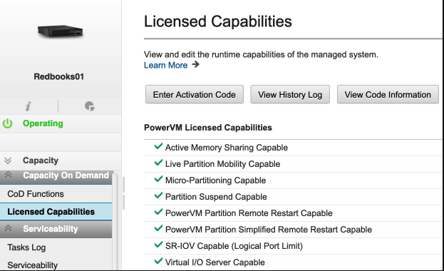
Figure 4-22 SRI-OV-capable on Licensed Capabilities
2. If the SR-IOV Capable feature is enabled, then check whether the physical network adapter is SR-IOV-capable. From the HMC, select the managed system name and then select Processor, Memory, I/O. Expand Physical I/O Adapters, and check whether the physical network adapter is SR-IOV-capable, as shown in Figure 4-23. This figure shows that the adapter is not SR-IOV-capable. You must use an SR-IOV-capable adapter that is an unassigned adapter.

Figure 4-23 Finding an SR-IOV-capable adapter
3. Modify the SRI-OV adapter and change the mode from dedicated to shared by following the steps in Modifying SR-IOV adapters, found at:
4. Modify the SR-IOV physical ports by following the steps in Modifying SR-IOV physical port settings, found at:
5. Add logical ports (LPs) to the partition (either VIOS or client LPARs) by following the steps in Adding SR-IOV logical ports, found at:
4.4 Creating and installing a client LPAR
This section describes the creation of a client LPAR and assigning resources to it.
4.4.1 Creating a client LPAR
To create a client LPAR, click All Systems, click the management system name, click Partitions from the left pane, and click Create partition, as shown in Figure 4-24.

Figure 4-24 Client LPAR creation
Enter the Basic Partition Configuration details, processor, and memory configuration for the client LPAR, as shown in Figure 4-25. Then, click OK to create a client LPAR.

Figure 4-25 Client LPAR Create Partitions
|
Note: Each virtual adapter slot consumes a small amount of memory. Therefore, as a best practice, assign a reasonable number of Maximum Virtual Adapters that is based on the requirement for client storage and network adapters.
After the LPAR is created, it is important to enable Save configuration changes to profile. For more information, see Saving Configuration Changes To Profile, found at:
|
Figure 4-25 shows more options as follows:
•Single Partition: Select this option to create a single partition.
•Multiple partitions: Use this option to create several partitions after you enter the processor and memory configuration. This option creates partitions without assigning any network or storage adapters, which can be assigned later to the partitions.
•Create from template: This option allows the creation of client LPARs from a predefined template. This template contains the configuration and resources, for example, processor, memory, virtual network, and virtual storage, and other features that can be set up based on your preferences. To create a partition from a template, see Creating a logical partition by using a template, found at:
To customize your own template, you can copy an existing predefined template, go to the HMC Enhanced GUI. Select HMC management → Templates and OS Images, as shown in Figure 4-26. Select Partition, and select one of the predefined templates. Click Copy and customize the template based on your preferences.

Figure 4-26 Templates and OS Images
4.4.2 Capturing and deploying VMs with PowerVC
In a PowerVC managed environment, VMs can be provisioned and installed by using the capture and deploy feature. For more information, see the following resources:
•Capturing a virtual machine, found at:
•Deploying captured or imported images, found at:
4.4.3 Client LPAR storage configuration
Two types of storage adapters can be assigned to a client LPAR:
•Virtual SCSI (vSCSI)
The disk on the client is backed by a logical or a physical device on the VIOS, which can be a physical volume, a logical volume, or logical unit (LU).
vSCSI is described in 2.3.1, “Virtual SCSI” on page 42. For planning considerations, see 3.5.1, “Virtual SCSI planning” on page 101.
For more information, see Virtual SCSI, found at:
•N_Port ID Virtualization (NPIV)
NPIV allows multiple LPARs to access SAN storage through the same physical FC adapter. For NPIV, SAN LUNs are presented directly to the client LPAR. VIOS is a pass-through between the SAN storage and the client operating system, so no LUNs are assigned to the VIOS.
NPIV is described in 2.3.2, “Virtual Fibre Channel” on page 43. For planning considerations, see 3.5.2, “Virtual Fibre Channel planning” on page 104.
For more information, see Virtual Fibre Channel, found at:
To assign a storage adapter to a client LPAR, follow these steps:
1. Click All Systems.
2. Click the managed system name.
3. Click Partitions.
4. Click the name of the newly created client LPAR.

Figure 4-27 Client virtual storage configuration
For more information about adding vSCSI-backed storage (physical volume, logical volume and shared storage pool (SSP) LUs), see Managing virtual SCSI resources for a partition, found at:
For more information about adding virtual Fibre Channel (NPIV), see How to DLPAR Virtual Fibre Channel Adapters Using the HMC Enhanced GUI, found at:
|
Notes:
•For NPIV, after the virtual Fibre Channel (VFC) adapter is created from the HMC Enhanced GUI, two virtual WWPNs are generated for each adapter. The primary WWPN must be zoned on the SAN switch and LUNs must be masked on the SAN storage.
•If LPM is used between Power servers (managed systems), you must zone the secondary WWPN on the SAN switch the same way that the primary WWPN is zoned. The same LUNs also must be masked to the secondary WWPN.
•Usually, SAN administrators prefer to scan the SAN switch to discover the client WWPN in preparation to zone it. If the client WWPNs cannot be discovered, then log in from the HMC Enhanced GUI. From the client LPAR, complete these steps:
a. Select Virtual Storage.
b. Select the Virtual Fibre Channel tab.
c. Click Log In.
d. After zoning is completed, click Log Off.
|
4.4.4 Client LPAR network configuration
Several types of client networking can be added based on the user’s preference:
•Virtual network
•SRI-OV
•Virtual Network Interface Controllers (vNICs)
•Hybrid Network Virtualization (HNV)
Virtual network
The following steps describe how to connect a client LPAR to a virtual local area network (VLAN) when a virtual network is used. This procedure creates a VEA on the client LPAR.
1. Click All Systems.
2. Click the managed system name.
3. Select Partitions.
4. Click the client LPAR name.
5. Click Virtual Networks on the left pane.
6. Click Attach Virtual Network and select the preferred VLAN to use on the client LPAR, as shown in Figure 4-28.
7. Click OK.

Figure 4-28 Attach Virtual Network window
SRI-OV
If SRI-OV logical port (LP) is selected as the network type for the client LPAR, see Adding SR-IOV logical ports, found at:
vNIC
If vNIC is selected as the network type for the client LPAR, for more information about how to create vNIC for the client LPAR, see vNIC Functionality Guide, found at:
Hybrid Network Virtualization
If the client LPAR participates in LPM, and you prefer to use SRI-OV for client LPAR networking, then you can use HNV. For more information, see Hybrid Network Virtualization - Using SR-IOV for Optimal Performance and Mobility, found at:
4.4.5 Installing the client operating system
This section describes the common installation methods to install an operating system on a client LPAR. These methods can be categorized as follows:
•Using a virtual optical device: A vSCSI adapter that is backed by a logical or physical device on VIOS. It can be a USB flash drive, USB optical drive (DVD-RAM or DVD-ROM), or a media repository ISO file.
•Using a physical device: USB flash drive or USB optical drive. The physical USB adapter must be assigned to the client LPAR. This method is not recommended if you plan to migrate the client to another managed system.
•Network Installation.
Virtual optical device
With the virtual optical device installation, the vSCSI adapter mapping is created between the VIOS and the client LPAR.
A virtual target device (VTD) is created under the vhost on VIOS. You can map either a physical USB optical device, a USB flash drive, or an image from the repository to the vhost.
For more information about the procedure to create the virtual optical device from the HMC Enhanced GUI (Figure 4-29), see Adding virtual optical devices, found at:

Figure 4-29 Add Virtual Optical Device
SSH in to VIOS and run the lsmap -all command to check whether the vhost and the test VTD were created, as shown in Figure 4-30.

Figure 4-30 The lsmap command output
•If a USB optical device (DVD-RAM or DVD-ROM) exists on VIOS, you can view the optical device name by running the following command:
$ lsdev -type optical
For more information, see Moving the DVD-RAM Between LPARs using the VIO server, found at:
•If the USB flash drive is assigned to the VIOS, you can view the USB flash drive by running the following command:
$ lsdev |grep -i usb
For more information, see Using and taking advantage from USB devices and AIX, found at:
•If the installation is being made from a media repository, you can view the images in the image repository by running the lsrep command on VIOS, as shown in Figure 4-31.

Figure 4-31 The lsrep command to list the available repository images that can be assigned to vhost2
For more information, see How to configure a VIOS Media Repository/Virtual Media Library, found at:
Alternatively, for HMC GUI instructions about managing a media repository, see the following resources:
•Adding or removing a media library, found at:
•Adding or removing media files from a media library, found at:
Regardless of the selected virtual device method, the command to map a device or file to vhost2 remains the same as follows:
$ mkvdev -vdev <device name> -vadapter <vhost#>
For example:
$ mkvdev -vdev <cd0| usbms0 | RHEL-8.2.0-20200404.0-ppc64le-dvd1.iso> -vadapter vhost2
Physical device
A physical USB device can be assigned to a client LPAR to install an operating system by going to the HMC Enhanced GUI and completing the following steps:
1. Select All Systems.
2. Click the managed system name.
3. Select Partitions.
4. Select Virtual Storage.
5. Click the client LPAR name.
6. Select Physical I/O Adapters.
7. Click Add Adapter.
8. Select the USB adapter.
9. Click OK.
Figure 4-32 shows the physical USB adapter assignment to the client LPAR.

Figure 4-32 Physical USB adapter assignment
Network installation
For network installation on AIX, a NIM can be used, which requires completing the following steps:
1. Download the AIX installation media (ISO files) from the IBM ESS website, found at:
2. Define lpp_source and SPOT. For more information, see How to create a spot and lpp_source from an ISO image, found at:
3. Allocate resources for network boot (nim_bosinst). See Installing a client using NIM, found at:
For IBM i network installation, see IBM i Network Installation Using HMC, found at:
For Linux network boot installation on Power, see Installing Red Hat Enterprise Linux on IBM Power System servers using network boot, found at:
There are several more methods that you can use to install Linux on your system. For more information, see Additional installation methods, found at:
Operating system installation
To install AIX, complete the following steps:
1. Activate the client LPAR in SMS boot mode.
2. Open a console session to the LPAR.
3. Select 5. Select Boot Options and then press Enter.
4. Select 1. Select Install/Boot Device and then press Enter.
5. Select 7. List all Devices, look for the virtual CD-ROM/USB (press n to get to the next page if required). Enter the number for the CD-ROM/USB and then press Enter.
6. Select 2. Normal Mode Boot and then press Enter.
7. Confirm your choice by selecting 1. Yes and then pressing Enter.
8. Next, you are prompted to accept the terminal as console and select the installation language.
9. You are presented with the installation menu. It is a best practice to check the settings (option 2) before you proceed with the installation. Check whether the selected installation disk is correct.
10. When the installation procedure finishes, use the padmin username to log in. On initial login, you are prompted to supply the password. There is no default password.
11. After successful login, you are placed under the VIOS CLI.
12. Enter a and press Enter to accept the Software Maintenance Agreement terms, then run the following command to accept the license:
$ license -accept
The AIX installation is complete.
For more information about a Linux installation, see Quick start guides for Linux on IBM Power System servers, found at:
For more information about an IBM i installation, see Preparing to install the IBM i release, found at:
4.5 VIOS security implementation
VIOS offers a set of options to tighten security controls in your VIOS environment.
Through these options, you can select a level of system security hardening and specify the settings that are allowed within that level. With the VIOS security features, you can control network traffic by enabling the VIOS firewall.
The system security hardening feature protects all elements of a system by tightening security or implementing a higher level of security. Although hundreds of security configurations are possible with the VIOS security settings, you can easily implement security controls by specifying a high, medium, or low security level.
You can edit the following security attributes with the system security hardening features that are provided by VIOS:
•Password policy and complexity settings
•System check actions, such as usrck, pwdchk, grpck, and sysck
•Role-based access control configuration (RBAC)
•Trusted execution and intrusion detection
•Firewall and IP filtering
For more information, see Security on the Virtual I/O Server, found at:
4.5.1 VIOS user types and role-based access control configuration
The VIOS operating system is based on the AIX kernel with a customization to serve the I/O operations to client LPARs.
The first user to log in to VIOS is padmin (prime administrator), which is the only active user type when the VIOS is installed.
The prime administrator can create more user IDs with types of system administrator, service representative, development engineer, or other users with different roles. You cannot create the prime administrator (padmin) user ID. It is automatically created and enabled, and the role PAdmin is assigned as the default role after the VIOS is installed.
For more information, see Managing users on the Virtual I/O Server, found at:
A root shell can be access with the oem_setup_env command for any AIX administration issues on the VIOS operating system. However, the virtualization tasks are done only by the padmin user that has access to the virtualization libraries.
You can use RBAC to define roles for users in the VIOS. A role confers a set of permissions or authorizations to the assigned user. Thus, a user can perform only a specific set of system functions that depend on the access rights that are given. For example, if the system administrator creates the role for user management with authorization to access user management commands and assigns this role to a user, that user can manage users on the system but has no further access rights.
For more information, see the following resources:
•Using role-based access control with the Virtual I/O Server, found at:
https://www.ibm.com/docs/en/power-sys-solutions/0008-DEA?topic=P8DEA/p8hb1/p8hb1_vios_using_rbac.htm
•How to use RBAC on VIOS, found at:
4.5.2 Configuring security hardening (viosecure)
You can configure VIOS security options with the viosecure command. To help you set up system security when you initially install the VIOS, VIOS provides the configuration assistance menu. You can access the configuration assistance menu by running the cfgassist command.
With the viosecure command, you can set, change, and view current security settings. By default, no VIOS security levels are set. You must run the viosecure command to change the settings.
For more information, see the viosecure command, found at:
viosecure also configures, unconfigures, and displays the firewall settings of the network. You can use the viosecure command to activate and deactivate specific ports and specify the interface and IP address of the connection. You also can specify to use the IPv6 version of the viosecure command to configure, unconfigure, and display the firewall settings of the IPv6 network.
For more information about using viosecure for setting up a firewall, see PowerVM: How to use viosecure firewall to deny access to a service for all except for specific IP?, found at:
viosecure can activate, deactivate, and display security hardening rules. By default, none of the security strengthening features are activated after installation. The viosecure command guides the user through the proper security settings, which can be high, medium, or low. After this initial selection, a menu is displayed that itemizes the security configuration options that are associated with the selected security level in sets of 10. These options can be accepted in whole, individually toggled, or ignored. After any changes, viosecure continues to apply the security settings to the computer system.
For more information, see IBM VIOS: How to create custom viosecure rules, found at:
VIOS security benchmark
VIOS security benchmark profiles can be applied by using a custom configuration that is part of the aixpert tool command, which can be integrated with PowerSC Security and Compliance features.
The Center for Internet Security (CIS) develops benchmarks for the secure configuration of a target system. CIS benchmarks are consensus-based, best-practice, security-configuration guides that are developed and accepted by business and industry.
The CIS specifications for VIOS server provide guidance for establishing a secure configuration by applying the new profiles.
For more information, see CIS specifications for VIOS server, found at:
Several customers are looking for security and compliance automation, which can be achieved with IBM PowerSC.
The PowerSC Security and Compliance Automation feature is an automated method to configure and audit systems in accordance with the US Department of Defense (DoD) Security Technical Implementation Guide (STIG), the Payment Card Industry (PCI) Data Security Standard (DSS), the Sarbanes-Oxley act, COBIT compliance (SOX/COBIT), the Health Insurance Portability and Accountability Act (HIPAA), CIS benchmarks compliance for AIX, and IBM i best practices.
PowerSC helps to automate the configuration and monitoring of systems that must be compliant with the PCI DSS 3.2. Therefore, the PowerSC Security and Compliance Automation feature is an accurate and complete method of security configuration automation that is used to meet the IT compliance requirements of the DoD UNIX STIG, the PCI DSS, t SOX/COBIT, and the HIPAA.
CIS benchmark guidelines are not maintained or supported by IBM; they are directly supported by CIS.
For more information, see Security and Compliance Automation concepts, found at:
4.6 Shared processor pools
Shared processors are described in 2.1.3, “Shared processors” on page 34 and 2.1.5, “Multiple shared processor pools” on page 36. For planning considerations, see 3.2.4, “Shared processor pools capacity planning” on page 82.
This section goes through the shared processor pools (SPPs) feature in PowerVM for allocating and controlling the right capacities.
The default SPP is preconfigured, so you cannot change the properties of the default SPP. The maximum number of processors that are available to the default SPP is the total number of active, licensed processors on the managed system minus the number of processors that are assigned to dedicated processor partitions.
Without using extra SPPs, unused processor capacity is divided among all uncapped LPARs according to their weights within the default SPP. When more SPPs are used, the distribution takes place in two stages. Unused processor shares are first distributed to uncapped LPARs within the same SPP. Only the unused processor shares that are not consumed by other LPARs in the same SPP are redistributed to LPARs in other SPPs.
For more information, see Processor resource assignment in partition profiles, found at:
Each SPP has an Entitled Pool Capacity (EPC), which is the sum of the guaranteed entitlements of the assigned LPARs and the Reserved Pool Capacity (RPC). The RPC can be configured by using the reserved_pool_proc_units attribute of the SPP and has the default value 0. Just as the entitlement is guaranteed for a shared processor LPAR, the assignment of the EPC is guaranteed for an SPP, regardless of how the shares are distributed to the associated LPARs in the SPP.
For more information, see Changing a shared processor pool, found at:
4.7 Active Memory Expansion implementation
Section 2.2.2, “Active Memory Expansion” on page 39 provides an overview of Active Memory Expansion (AME). Section 3.3.2, “Active Memory Expansion planning” on page 90 includes planning considerations.
This section describes how AME can be configured and implemented.
4.7.1 Activating AME
AME can be enabled through the HMC or the PowerVC dashboard. Before you enable AME, verify that your server supports AME (that is, it is AME-capable), as shown in Figure 4-33.

Figure 4-33 AME support on the server
After AME is activated for a server, the feature can be enabled for multiple LPARs that are hosted on that server.
Figure 4-34 summarizes the steps to enable AME for an LPAR.

Figure 4-34 Enabling AME for LPAR
Choose the correct Expansion Factor when AME is enabled.
The AME planning tool (amepat) that is provided with AIX helps to analyze the workload and provides suggestions for reasonable physical memory size and the respective memory expansion factor. Figure 4-35 shows the amepat command output.

Figure 4-35 The amepat command output
In this output, the optimum memory size is 5.5 GB with a memory expansion factor of 1.82. With these settings, the operating system in the partition still sees 10 GB of available memory, but the amount of physical memory can be reduced by almost half. A higher expansion factor means that more CPU resources are needed to perform the compression and decompression. Therefore, choosing the higher value of expansion factor might lead to a higher memory deficit.
For more information, see the amepat command, found at:
For an AME-enabled LPAR, monitoring capabilities are available in standard AIX performance tools, such as lparstat, vmstat, topas, and svmon. amepat is included with AIX, which enables you to sample workloads and estimate how expandable the partition's memory is, and how many CPU resources are needed.
For more information, see Active Memory Expansion (AME), found at:
Temporary activation of AME
AME is a chargeable feature, which can be purchased separately. You can evaluate the usage of AME at no charge with Trial Capacity on Demand (Trial CoD). With Trial CoD, the AME function can be temporarily activated for up to 60 days at no charge. Trial AME is available once per server and it allows users to validate the benefits that your server can realize.
CoD is described in 2.9, “Capacity on Demand” on page 66.
For more information, see Other Capacity on Demand Advanced Functions, found at:
4.8 Active Memory Mirroring implementation
Active Memory Mirroring (AMM) is described in 1.3.19, “Active Memory Mirroring” on page 21.
Enabling AMM for the hypervisor doubles the amount of memory that is used by the hypervisor, so available memory for LPARs in the system is affected.
The IBM System Planning Tool (SPT) can provide the estimated amount of memory that is used by the hypervisor. This information is useful when changes are made to an existing configuration or when new servers are deployed.
For more information, see IBM System Planning Tool for Power processor-based systems, found at:
Figure 4-36 highlights the options that must be selected to estimate the amount of memory that is required by the AMM feature.

Figure 4-36 Estimating AMM usage by using IBM System Planning Tool
Besides the hypervisor code itself, other components that are vital to the server operation also are mirrored:
•Hardware page tables (HPTs), which are responsible for tracking the state of the memory pages that are assigned to partitions.
•Translation Control Entries (TCEs), which are responsible for providing I/O buffers for the partition’s communications.
•Memory that is used by the hypervisor to maintain partition configuration, I/O states, virtual I/O information, and partition state.
It is possible to check whether the AMM option is enabled and change its status by using the HMC. The relevant information and controls are in the Memory Mirroring section of the General Settings window of the selected Power server, as shown in Figure 4-37 on page 177.

Figure 4-37 Memory Mirroring section in the General Settings window on the HMC GUI
If one of the DDIMMs that contains hypervisor data fails, all the server operations remain active and the eBMC service processor isolates the failing DDIMMs. The system stays in the partially mirrored state until the failing DDIMM is replaced.
Memory that is used to hold the contents of platform dumps is mirrored. AMM does not mirror partition data either. It mirrors only the hypervisor code and its components to protect this data against DDIMMs failures. With AMM, uncorrectable errors in data that is owned by a partition or application are handled by the existing Special Uncorrectable Error (SUE) handling methods in the hardware, firmware, and operating system.
SUE handling prevents an uncorrectable error in memory or cache from immediately causing the system to stop. Rather, the system tags the data and determines whether it is ever used again. If the error is irrelevant, it does not force a checkstop. If the data is used, termination can be limited to the program, kernel, or hypervisor that owns the data, or freeze of the I/O adapters that are controlled by an I/O hub controller if data must be transferred to an I/O device.
All Power10 processor-based enterprise and scale-out servers (except the Power S1014) support the AMM feature.
For more information, see the following IBM Redpapers:
•IBM Power S1014, S1022s, S1022, and S1024 Technical Overview and Introduction, REDP-5675
•IBM Power E1050: Technical Overview and Introduction, REDP-5684
•IBM Power E1080 Technical Overview and Introduction, REDP-5649
4.9 Live Partition Mobility implementation
LPM is described in 2.6.1, “Live Partition Mobility” on page 54.
You must verify that the source and destination systems are configured correctly so that you can successfully migrate the partition. This verification must cover the configuration of the source and destination servers, the HMC, the VIOS LPARs, the partition, the virtual storage configuration, and the virtual network configuration.
For more information about this procedure, see Preparing for partition mobility, found at:
The FLRT Live Partition Mobility (LPM) report provides recommendations for LPM operations based on source and target input values. These recommendations might include recommended fixes, including interim fixes, for known LPM issues.
For more information about this tool, see Live Partition Mobility Recommendations, found at:
For a list of LPM best practices, see Best Practices for Live Partition Mobility (LPM) Networking, found at:
For a description of the most common causes that impact LPM performance and considerations to resolve the problem, see Live Partition Mobility Performance, found at:
For more information about how to enable NPIV LUN or disk-level validation on a VIOS for a partition mobility environment, see How to Enable/Disable NPIV LUN or Disk Level Validation on a Virtual I/O Server (VIOS) for Partition Mobility Environment, found at:
4.10 PowerVC Implementation
Before you can install and use PowerVC, you must ensure that your environment is configured correctly. The environment must be using supported hardware and software with storage, hosts, and network resources configured.
The tasks that are involved in setting up your environment vary depending on whether you are installing PowerVC in an existing environment or in a new environment. For new environments, you might be using new hardware or repurposing existing hardware to create your environment.
For more information about planning and configuration, see Setting up the PowerVC environment, found at:
PowerVC can be deployed on a virtual machine (VM), and as a best practice, PowerVC should be the only application on that VM. However, PowerVC can generally coexist with other software on the same instance, assuming that there is no resource or dependency conflict between PowerVC and the other software. Potential conflicts include, for example, port contention, user namespace, file system capacity, and firewall settings.
You must consider performance implications to PowerVC and the other software when you install other software on the same instance. For example, PowerVC memory usage might grow and cause problems with applications that coexist with PowerVC. PowerVC resource requirements are sized by assuming that PowerVC is the only workload that is running on the management instance. If other applications are using resources, adjust the sizing as required.
Consider the following points before you start the PowerVC installation procedure:
•Make sure that the managed hosts are on an IBM Power8 processor-based server or later.
•If you have any previous version of PowerVC that is installed, take a backup, copy the backup file to a custom location, and then uninstall the existing version. Restart the system and install the new version of PowerVC.
•Review the hardware and software requirements.
•For RHEL and SUSE Linux Enterprise Server, a PowerVC 2.1.0 installation is supported on both single-node and multinode environments.
•Make sure that you disable IPv6 before you proceed with the installation procedures.
To install PowerVC, complete the following steps:
1. Configure these repositories for RHEL and SUSE Linux Enterprise Server as based on the environment:
– A YUM repository for PowerVC that is installed through RHN. Make sure that the following repositories are enabled.
• AppStream
• BaseOS
• Supplementary
• HA
• Ansible
– A Zypper repository for PowerVC that is installed through SUSE Linux Enterprise Server 15 SP2 and SUSE Linux Enterprise Server 15 SP3. Make sure that the following repositories are enabled.
• SLE-Module-Basesystem
• SLE-Module-Desktop-Applications
• SLE-Module-Development-Tools
• SLE-Module-Legacy
• SLE-Module-Public-Cloud
• SLE-Module-Server-Applications
• SLE-Module-Web-Scripting
• SLE-Product-HA
• SLE-Product-SLES
2. Extract the compressed file that matches your environment to the location from which you want to run the installation script:
– For ppc64le, extract download_location/powervc-opsmgr-<rhel or sles>-ppcle-<powervc_version>.tgz, where download_location is the directory to which the file was downloaded.
– For x86_64, extract dvd_mount_point/powervc-opsmgr-rhel-x86-<powervc_version>.tgz, where dvd_mount_point is the directory where the ISO image was mounted.
3. Change the directory to extract location/powervc-opsmgr-<version>, where the extraction location is the directory that you extracted.
4. After the installation is complete, access IBM Fix Central to download and install any fix packs that are available. For more information, see IBM Fix Central, found at:
After you install PowerVC, you can add, configure, and manage the resources. For more information, see Adding resources to PowerVC, found at:
After you install PowerVC, you can access it by opening your browser and entering the URL https://powervc_hostname or https://powervc_IP_address. Then, you can log in to PowerVC for the first time with the root credentials of the management host where PowerVC is installed.
|
Note: To register resources, you must sign in with the credentials of a user with the admin role.
|
For more information, see Getting started with PowerVC, found at:
..................Content has been hidden....................
You can't read the all page of ebook, please click here login for view all page.