
This chapter discusses six main topics. They are all imaging techniques that deviate from the ‘usual’ techniques discussed up to this point. They may require particular skills, material and apparatus such as special filters, films or sensors, dedicated lenses, viewing devices, etc. Infrared (IR) photography, ultraviolet (UV) reflectance and UV fluorescence photography are used often to determine properties in captured scenes that are not distinct enough or even invisible under visible light. Underwater photography needs specialized waterproof equipment. Panoramic photographs can be created using an array of techniques and equipment, from conventional to very specialized. Stereo imaging requires pairs of cameras with matched lenses, linked shutters and diaphragms. The results, which appear three-dimensional, are often viewed with specialized accessories. Finally, working with liquid emulsions as well as transferring pictures from Polaroid material comes under the heading of home-made printmaking.
Photographing the invisible
The human eye is limited to perceive only a very small part of the electromagnetic spectrum which extends from the blue-violets to deep reds at wavelengths from 380 to 700 nm. The sensitivities of photographic material and sensors extend beyond the visible and can record properties in the world around us that the eye does not see. The interaction, by way of reflected or absorbed energy from particular subjects of UV or IR rays yields information that can be used for scientific purposes, but equally may enrich the creative photographic experience. The properties and proper use of photographic sources, media and methods for recording beyond the deep reds and the blue-violets are discussed later.
Infrared photography
Infrared photography uses a small part of the invisible infrared spectrum – wavelengths ranging from about 700 to 1200 nm – which extends beyond the deep reds. This part of the infrared spectrum is referred to as near infrared to distinguish it from far infrared which is the spectral region used in thermal imaging. Traditionally, infrared images were captured using a black and white film, or a ‘false-colour’ infrared reversal film. With the use of digital cameras today infrared photography is easier than ever.
Infrared properties
To make most of your photographic sources and the scenes that you capture it is important to know some basic properties of infrared radiation. To start with, infrared is strongly reflected by chlorophyll. This is why in final prints of infrared photographs any living green flora (plants, leaves on trees, etc.) appears whitish and, if under strong sunlight which provides plenty of infrared, snow-like or luminescent. There is a small contribution from chlorophyll fluorescence but this is not the main reason why foliage appears bright in infrared photographs. Chlorophyll reflectance makes infrared photography important to agriculture and forestry applications.
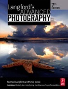
There is a strong absorption of infrared by water and moisture in the atmosphere. Thus, often lakes, but also clear skies, appear very dark in prints with small white clouds standing out starkly (see Figure 13.1). All these characteristics give a strange dream-like atmosphere to scenes and can be very attractive. Because of the penetrative properties of infrared, there is a slight diffusion of detail when images are recorded, specifically on of Kodak high-speed infrared film. This is a property of this film only but adds to the ethereal mood.
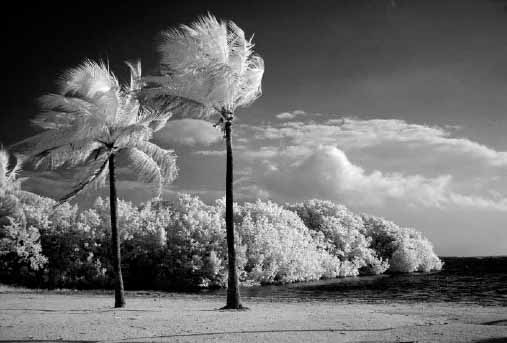
Figure 13.1 Living green flora appears whitish while the sky and the water appear dark in this infrared image.
Infrared has the ability to penetrate where visible light cannot. It penetrates the top layers of the epidermis and is reflected back from deeper in the skin. Portraits are turned into weird-looking macabre faces with translucent facial tones and bleached lips. Also, the visibility of the veins is accentuated. Haze penetration (that is in dry atmosphere, but not vapour, fog or smoke) by infrared is caused by reduced scattering in the atmosphere compared to visible light. That makes often distant landscapes look exceptionally clear with plenty of detail and is the reason infrared is commonly used in long-distance and aerial photography. All glasses transmit infrared, but also plastic, and some types of inks and paints transmit infrared. The infrared penetrative properties turn this type of photography into a useful tool in police investigations, such as forgery detection, where invisible details underneath document surfaces can be picked up in photographic prints. In museum application it is used for restoration or historical purposes to discover any underlying layers in paintings and other artefacts, or to differentiate inks and pigments. In medicine it is used to image clotted veins and poor blood circulation.
Infrared sources and filters
Apart from the sun which provides ample infrared, artificial light sources are also very common in subject lighting. Since heat emission is accompanied by infrared radiation, the tungsten filaments in incandescent lamps and in photoflood and flash lamps are especially suitable as they heat metal filaments to incandescence (see Chapter 4). They have the peak of their emission in the part of the infrared where the films and sensors have their maximum sensitivity. Electronic flash tubes are also excellent near infrared sources whereas fluorescent tubes used for indoor lighting have poor infrared emission. Bear in mind that it is possible to record radiated heat from objects from above approximately 300°C to incandescent temperature. Most infrared photography is accomplished by infrared shone on subjects and reflected back to the camera, as little infrared is emitted by non-incandescent bodies.
Unless you use a filter to block visible light your infrared films and digital camera sensors (with infrared blocking filter removed) will record both infrared and light reflected from the scene. Blocking partially or totally the visible light is achieved by deep red filters which stop blue and green wavelengths or visually opaque filters, called barrier filters, with various cut-off points. It is possible to record infrared only in the darkness by filtering the light source, so that only infrared reaches and is reflected from the subject (Figure13.2). In most cases barrier filters are fitted over the lens, for example the Kodak Wratten, series #87, #88A, #89A, Hoya #72 and others (Figure 13.3).

Figure 13.2 Fitting a black-looking filter over the flash window allows you to take pictures without the flash seeming to fire. The flash unit may also have an infrared prepulse unit for autofocusing.
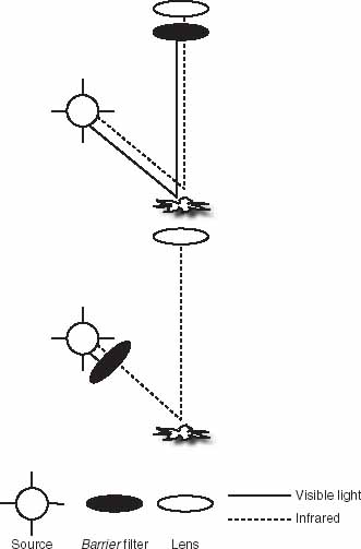
Figure 13.3 You can filter visible light and record only infrared reflected from your subject by placing a barrier filter either in front of the lens (top) or in front of the light source (bottom).
Traditional photographic techniques
Two or three brands of infrared-sensitive film and one brand of infrared colour reversal film are produced today. Most cameras can be used for infrared photography with the exception of plastic-body cameras (infrared penetrates plastic, see page 303) as well as cameras that have infrared sprocket-hole sensors that will fog infrared film. Also, not all dark slides and bellows in large format cameras are opaque to infrared radiation and should be tested before use in infrared photography. Most camera lenses are not designed to focus infrared exactly at the same point of focus as visible light, as they usually refract infrared radiation a little differently from the visible. You need to compensate for this focal shift or shoot at a high enough f-stop to cover focus errors. When the lens of a single-lens reflex (SLR) camera is covered with a barrier filter that is opaque and stops visible, focusing through the lens becomes impossible. If lenses have a red point on the side of the lens-setting mark, you should focus visually (manually or using autofocus), note the subject distance reading at the regular lens mark, then reset manually the distance against the red dot instead and finally place the filter in front of the lens (Figure 13.4). A tripod is necessary while you compose the picture.
The accuracy of your exposure metering system is not predictable. It will depend on the individual sensors’ infrared response, the absorption, reflection and transmission of infrared in the scene and the film you are using. One technique is to use a hand-held meter set to International Organization for Standardization (ISO) 50 for Kodak infrared film and take the reading without the filter. This will read out approximately correct exposure settings for the camera with a deep-red filter over the lens. It is always safest to shoot a bracketed series of exposures.
Infrared-sensitive films need cold storage as they are prone to fogging from thermal events. Also, the sensitizing dyes employed tend to be less stable than in other films and exposed film should be promptly developed. Films should be loaded and processed in total darkness and using metallic tanks to avoid fogging (remember infrared penetrates plastic). Standard developing solutions are used for infrared material, although prolonged development is recommended. Note finally that the large grains in infrared films make image noise a part of the infrared look.

Figure 13.4 Red spot denotes focus setting for infrared. If visible light from your subject is sharply focused when the lens is set for 10 m (top), then re-set 10 m against the spot (bottom).
Infrared photography using a digital camera
The charge-coupled device (CCD) and complementary metal-oxide semiconductor (CMOS) arrays in digital cameras have an inherent sensitivity to infrared. The only difficulty in using them for infrared photography is that cameras are equipped with infrared blocking filters in front of the light-sensitive array that stop infrared radiation which enters the lens and degrade visible light image quality in ‘normal’ photography. Removing the infrared filter is a possibility in some camera models. Otherwise, with the infrared blocking filter in place you can still use a barrier filter, give more exposure and capture only deep red and infrared. Exposure compensation depends on how your camera sensor reacts to the infrared, how much infrared the camera filter is blocking and on the barrier filters you are using (Figure 13.6). It will also vary with infrared source and scene properties (Figure 13.5).

Figure 13.5 An infrared image captured with a Canon EOS 5D digital camera.

Figure 13.6 (a) Transmittance of various B&W filters used for infrared photography. Reprinted with permission from Schneider Kreuznach. (b) Silicon photodiodes are sensitive to infrared. Image from ‘Sam’s Laser FAQ’, © Samuel M. Goldwasser, www.repairfaq.org.
In non-SLR digital cameras, real time viewing of the picture on the liquid crystal display (LCD) helps exposure, composition and focusing. You can use auto-exposure and autofocus that in most cases work well. In digital SLRs exposure is measured by a different sensor than the imaging sensor, which probably has a different response to infrared. Thus, you cannot rely on auto-exposure. Additionally, when using any SLR in which viewing is accomplished through the lens you will need to compose and focus the picture without the infrared (barrier) filter, then put it on and shoot. White balance is best carried out in custom mode, with the infrared filter fitted and while pointing the camera at foliage, which reflects most of the infrared, at least in outdoor scenes.
Your final RGB digital images will appear having a reddish or purple tint that will vary according to the camera and the filters you use. Postprocessing usually includes image de-saturation or conversion to greyscale and tone adjustments such as tonal stretching. In case you want to retain some colour information, you can always manipulate the RGB channels individually (see Chapter 11). Digital infrared photographs may be noisier than your ‘normal’ photographs. Noise can be removed quite successfully with various noise reduction filters. Slight sharpening is commonly used to bring up other important detail.
UV photography
UV photography can be split into two types: UV reflectance and UV fluorescence. In UV reflectance the photographic record is made of UV radiation reflected from the subjects. In contrast, UV fluorescence employs UV radiation to illuminate (and excite) certain materials which then ‘glow’ with white or coloured visible light that is captured. Other types of radiation can be used to produce fluorescence, but UV is the most common.
UV properties and applications
Similarly to infrared, only a part of the UV spectrum is used in UV imaging. Long UV wavelengths from 340 to 400 nm can be transmitted by photographic glass lenses but shorter ones in the middle and far UV region require quartz or fluorite lenses. Below 200 nm is the vacuum UV, named as such because air does not transmit it and thus it cannot be used for photography. Various optical media transmit UV in a different fashion. UV below 350 nm is poorly transmitted by regular optical and window glass and various plastics. Modern photographic lenses have restricted transmission to 400 nm, especially when are coated with anti-reflection material.
Much of the UV radiation is harmful. Fortunately, ozone in the upper atmosphere absorbs most of the harmful UV coming from the sun. Considerable amounts are however found at sea level due to scattering. It can cause reddening of the skin, is dangerous for the eyes and can cause snow blindness. Long-term exposures to UV causes premature yellowing of the eye and cataract, premature aging of the skin and skin cancer. It is imperative that you use precautions around UV sources. Avoid staring directly at any UV lamps unless your eyes are protected with UV-absorbing goggles.
Owing to shorter wavelengths UV is scattered more than visible or infrared wavelengths. It does not have as strong penetrative properties as infrared, although long-wave UV radiation penetrates deeper into the skin than visible light does. UV reflectance photography is widely used to record, just a few millimetres under the surface of the skin, areas of strong pigmentation. There is virtually no penetration of UV into the tissues, therefore there is no scattering. This results to sharper pictures of the top layers of the skin surface. UV reflectance is a useful method for visualization of skin aging, the damage produced by the sun, tattoos, birthmarks, fingerprints, freckles and ageing spots.
In archaeology and museum applications photographs taken in UV illumination can reveal the structure of a painting’s surface layers. UV causes varnishes to fluoresce, and the specific manner and colour of the fluorescence aids in identification of retouching and overpainting or differences in painting pigments.
Reflective UV photography reveals old bruising and bites that are no longer visible. It also works well for cuts, scratches and scars, and organic fluid compounds. This makes it a valuable tool in crime scene investigations. Other types of physical evidence that may fluoresce under UV are fingerprints, gunpowder, footwear impressions and clothing fibres. Further forensic applications include examination of old faded documents under UV to obtain better sharpness. Also, different inks show a difference in visible fluorescence when illuminated with UV sources.
UV aerial photography of snowy regions helps in the identification and counting of animals with white coat that reflects all visible wavelengths. While the snow also reflects strongly UV (which explains why it is so easy to get a sunburn while skiing), an animal’s coat absorbs it. Other applications where UV imaging is important include astronomy and remote sensing.
UV photography may be used less often than infrared for creative purposes but you can certainly produce very pleasing imagery by employing UV techniques. In exterior scenes foliage appears darkish due to low UV reflectance (unlike infrared), while water is very bright because the surface reflects plenty of UV (this is why we also get sunburned when swimming). Flowers emerge differently than in visible records because there are different amounts of UV reflected from flower petals, often much less in the central area of the flower. Also, the nectar glands and pollen may fluoresce under UV illumination (Figure 13.7). UV visible marks on the petals attract bees – which have a UV-enhanced vision – towards the nectar and pollen of the flowers. This makes UV imaging useful to natural scientists.

Figure 13.7 Image illustrating UV fluorescence of pollen. © Bjørn Rørslett/ NN/Samfoto.
UV sources and filters
There are various UV sources with different compositions and methods of use. As with all types of photography sunlight is the most available and cheapest source but the intensity of UV is very variable. It contains long, short and some middle wavelengths of UV. Although much of its short and middle UV content is lost on its way to the earth’s surface, much of the long passes through the atmosphere, especially in bright sunny days. In contrast, common tungsten and tungsten– halogen lamps which are rich in infrared are poor UV sources; the latter when operated in high temperatures and contained within a quartz envelope emit some UV.
UV fluorescent tubes coated with a special phosphor (Wood’s Coating) absorb most visible and transmit most UV with long wavelengths used in photography. The tubes appear as a very deep violet-blue and they are referred to as ‘black lights’. They are the most available UV sources. Another suitable artificial source is the electronic flash which can be used efficiently in combination with aluminium reflectors. Be aware, as often flash units have UV-absorbing glass over the flash tube for the purpose to reduce UV output. This must be removed before the exposure. Otherwise high- and low-pressure discharge lamps emit some strong UV lines. Arcs provide substantial emission of UV and are still used as primary sources in photography. The xenon arc lamp is a pretty good continuous source of UV.
As with infrared, you need to use blocking filters to record only the UV reflected from your subjects. These UV-transmitting filters, such as the Hoya U-360 or the Kodak Wratten 18A, are commonly known as ‘black light filters’; they may have some violet and infrared transmittance too. In contrast, photographic UV-absorbing filters with spectral transmissions named as ‘UV’, ‘haze’, ‘skylight’ are related to Kodak Wratten series such as 1A and 2B–2E.These absorb UV radiation and reduce the effects of haze without affecting the rendering of visible colours. Absorbing UV filters protect from harmful UV and can be found in sunglasses, goggles and protection sun lotions. In photography glass filters are placed over the lens to avoid much UV to fall on films and camera sensors, to which they are naturally sensitive. Use ‘barrier’ UV filters that almost totally block UV when you want to record only the fluorescence from subjects that occurs in the visible (Figure 13.8). For UV fluorescence an exciter filter can be placed over the source to allow only those wavelengths through which will cause fluorescence.
Figure 13.8 For recording UV fluorescence use a UV barrier filter to stop UV entering the lens so that you can only record the fluorescence from the subject (top). In UV reflectance use a visible barrier filter so that you can record only the UV reflected from the subject (bottom).
UV reflectance techniques
In UV reflectance photography the reflected UV from the subject is captured while visible is blocked with UV exciters in front of the camera lens. All silver halide films, including colour negative and slide films, are sensitive to near UV although pure UV images are recorded only in the blue-sensitive layer. For striking, unusual imaging you can use false-colour infrared slide with appropriate filtration to block the visible and capture simultaneously UV and infrared reflected from the subject, with the UV recorded on the blue and the infrared on the red-sensitive layers. Images formed with UV tend to be low in contrast and therefore high-contrast films or development should be preferred. Exposure times vary from 4 to 15 stops over what is needed for capturing the visible. Photographing UV reflectance requires a lens that passes sufficient amounts of radiation, thus less compensation is required when using quartz lenses. In any case it is necessary to use a tripod and bracket exposures. Owing to long exposures reciprocity law failure effects may be present.
Remember that UV focuses in a different point to visible, but the focus point displacement is opposite to that of infrared. Unlike infrared photography, correction is not achieved by altering the lens’s focal point as there are no UV markers on any SLR lenses. To achieve sharper results focus on the subject in visible light and then close down the aperture to obtain more depth of field. The shorter the focal length the less stopping down you need. Test exposures are the best means for determining the optimum aperture.
Digital camera sensors without UV blocking filters respond to UV too, but are not used as much as they are for infrared recording. Exposure compensation depends largely on your sensor’s response and the lens’s UV transmittance. It also depends on the available levels of UV radiation and the filter’s transmittance. When using non-SLR cameras real time viewing of the picture on the LCD helps exposure – which can be handled usually quite well by the camera – focusing and composition. One way to ensure correct exposure is to check the LCD histogram. As in the case of infrared, RGB digital images are weirdly coloured, with some cameras yielding bluish and some pink or magenta results. Contrast is also low. Since you might end up with relatively long exposures digital noise is likely to degrade your pictures. Similarly to infrared, post-manipulation is required to turn images to black and white or to ‘false-colour’ records. See infrared photography above for colour manipulation techniques, noise removal and contrast optimization.
UV fluorescence techniques
In UV fluorescence a visible record is obtained from subjects that glow when they are illuminated with UV, whilst UV barrier filters block the UV from entering the lens. Fluorescent part of the subject will glow brightly and you will record exactly what you see (without the barriers the subject is recorded as if bathed with blue light, blotting out most colours). To photograph the fluorescence excited by UV usual colour films and digital sensors can be used. To capture only the glowing visible wavelengths you need to work on a blacked-out studio with your subject illuminated by one or more UV lamps, which usually emit a dim blue light. For controlled fluorescence, use exciter filters over the source. Indoors you might choose to add a little visible daylight from back, the side or the rear. Otherwise the fluorescent parts of the subjects will bath in a black sea. Outdoors natural light does this job, but you might want to filter out some reflected wavelengths, using appropriate colour filtration, to allow mostly the coloured fluorescence to pass.
Apart from flowers, minerals are good subjects for creative photography as well as especially designed plastic jewellery, day glow inks on posters and graphiti sprays (Figure 13.9). Even washing liquid, face powder and teeth will glow to a greater or lesser extent. Some parts of banknotes and labels for consumer products will also fluoresce when illuminated with UV. Measure exposure from the fluorescing parts using regular techniques with your camera or light meter. Spot measuring is often best. Be always aware of the danger of the UV lamps, so use UV-absorbing goggles.

Figure 13.9 You can use several products for creative photography using UV lighting.
Underwater photography
Most underwater photography is intended to show fish and plant life. However, you may also want to take underwater pictures of products, ranging from industrial equipment to fashion items (Figure 13.10). Yet another facet is record photography of wrecks, archaeological objects or marine engineering subjects.

Figure 13.10 An impressive angle on the butterfly stroke, showing how an Olympic swimmer expels air underwater. Chris Smith took this sport shot sitting at the bottom of the pool using a 35 mm lens on a conventional SLR camera.
You can photograph small objects, fish and plants in a glass-sided aquarium. True underwater photography, however, means shooting with your equipment submerged. Apart from having waterproof equipment you have to also be aware of the changes created while imaging in the water and not in the air, as refraction of the light rays in water is greater than refraction in the air (see Langford’s Basic Photography). As a result, underwater subjects appear closer and larger than they actually are. This upsets distance guessing and focusing, but otherwise the camera is affected the same ways as your eyes. Never underestimate the potential dangers of diving underwater and try to always have one other person with you.
Photographic equipment and techniques
Water causes serious spectral absorptions. As a result, daylight reduces in intensity and changes colour content (loosing red) with increased depths. Beyond approximately 10 m depth there is no colour differentiation and natural daylight is blue-green. For greater penetration it is best to work at around noon, when sunlight is closest to a right angle to the water and there is less reflection off the surface. Below 10 m, the blue-green cast can be photographically corrected by filtering, using 30 or 40R filters for example. Ultimately, the corrective filtration will depend on depth and water turbidity. Automatic white point correction can be problematic when using most digital cameras. Often white balanced underwater images have a pink or purple cast and look unnatural. Shooting at RAW image format can help digital post-shooting white point correction. If you want to shoot general views, for which only natural daylight is appropriate, better shoot in shallow waters (Figure 13.11). For close work and at depths where only blue twilight remains flash, strobes and battery lamps are the only satisfactory ways to show bright, faithful subject colours. Be also aware that water turbidity and the concentration of suspended matter, such as plankton, will introduce backscatter of any incident light. Loss of visibility underwater is largely due to backscatter, so is loss in contrast. To avoid backscatter, you have to move the light source away from your camera. A waterproof flashgun on a long-jointed arm, which positions the light well to one side of the lens axis and closer to the subject, is the best option. Light from the flash or strobe should ideally supplement the existing light unless you shoot in caves or shipwrecks where daylight is nonexistent. However, synchro-sunlight is virtually impossible underwater unless the water surface is included in the shot.
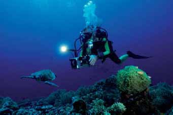
Figure 13.11 Diver working with a camera in an underwater casing. Water filters out longer wavelengths from daylight, giving a typical blue/cyan cast. Fit a compensating reddish filter or shoot with flash to render the colours faithfully.
There are two approaches to underwater camera equipment. Most often, an underwater housing for conventional cameras, such as a 35 mm, digital SLRs or compact cameras, is used. Here rods attached to the main camera controls pass through the casing to oversize knobs on the outside and access the controls inside (Figure 13.12). Such housings can be expensive but safe down to depths of around 40 m, ample for practically all professional sub-aqua assignments. They also have connectors to attach external flash units. Housings allow the lens to look through a domed port, or a flat port. Dome ports are used for wide-angle lenses, the curvature of the dome is ideally matched to the lens’s focal length. The dome creates a virtual image that lens focuses on. Often a dioptric supplementary lens is required on the camera to facilitate this. Dome ports do not introduce problems associated with refraction, radial distortion and axial chromatic aberrations (see page 44). Flat ports are used with long lenses for close-ups or shots that start or end above the water; they do not require a dioptre. Flat ports are unable to correct for the distortion produced by the differences between the indexes of light refraction in air and water. They introduce refraction, distortion and chromatic aberration problems when used underwater (see Figure 13.13).

Figure 13.12 Digital SLR camera housing, with flash on a long adjustable extension arm. Flash should not be directed from the camera, but from well to one side.
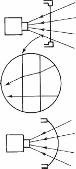
Figure 13.13 When a flat glass port is used on an underwater housing (top and centre) oblique image light is distorted. Domed port (bottom) presents the glass at right angles to all rays.
In some cases the housings are made with other additional optics to make the apparent angle of view wider. This is particularly useful to some digital cameras with small sensors that do not achieve wide angles of view with the conventional lenses. Both wide angle and close-up supplementary lenses are available, often as ‘wet lenses’ that can be added or removed underwater.
Alternatively, you can use a 35 mm film camera system specially designed with a waterproof metal body and lens, such as the Nikonos produced by Nikon. These cameras became obsolete in 2001 but are still the preferred choice of some keen underwater photographers. Amphibious cameras are nowadays made by Sea & Sea, Reef and other manufacturers. Otherwise, digital underwater cameras are often ‘normal’ cameras provided together with waterproof housing and settings such as focus, exposure programs and flash modes, for both land and underwater photography.
All lenses narrow their angle of view by 30% when used in water instead of air. For example, an extreme focal length type, such as a 21 mm on a 35 mm camera reduces its angle of view to that of a 30 mm lens in air. All other lenses tend to be of shorter rather than longer focal length, because you need to minimize your distance from the subject due to lack of clarity underwater (Figure 13.14). Wide-angle lenses are by far the most useful choice underwater. They allow you to get everything in from a shorter lens-to-subject distance, so you suffer less light loss and contrast flattening from particle backscattering. Macro lenses are also useful, as the subject is often only inches away from the camera (Figure 13.15). With macro lenses, distortions caused by refraction are not an issue. Note that when using macro lenses, you are more likely to use strobe light for the exposure. The subject will often be too close to the lens and the available sunlight will probably not suffice. A strobe is required for correct colour balance at all depths below about 3 m if accurate colour rendition is required. Otherwise, most underwater camera lenses do not give satisfactory quality on land (the scale of focusing distances also alters). However, if the camera accepts a range of interchangeable lenses, one of these is likely to be designed for use in non-underwater situations such as surfing and other marine sports.
Finally, wear the smallest volume face mask so that you can get your eye as close as possible to the eyepiece. If possible, change the regular SLR pentaprism for a sports action optical viewfinder – this lets you see the whole focusing screen from several inches away. Good housings will provide viewfinder correction optics to aid underwater use. Compact cameras often have a sports finder.

Figure 13.14 Ken MacLennan Brown shot this life size picture of juvenile squid on Fuji Velvia film, with a 35 mm Nikon F90x, equipped with a 105 mm lens in Subal housing.
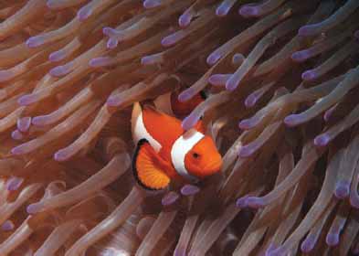
Figure 13.15 Image shot with a Nikon D80 camera in a Sea&Sea housing. The lens was a Nikkor macro 60 mm and the subject was lit with a flash. ISO 100, 1/125 second, f/11. Photograph by Muna Muammar.
Panoramic photography
Panoramic photography covers, more or less, all types of imaging with fields of view wider than the eye, while maintaining sharpness in the entire picture. Wide-angle photography can also be referred to as panoramic, however, true panoramic images give an impression similar to that when looking at a scene slowly while rotating your head from side to side (horizontally), or from up to down (vertically) and have, in general, large aspect ratios. Complete panoramas cover 360° views. Panoramic photographs give new life to large groups, open landscapes, cityscapes and large interiors. The picture proportions are interesting and dramatic and results helpfully exaggerate depth and distance.
When shooting panoramas it is a good idea to avoid subjects in the immediate foreground which will reveal distortion, unless you aim for a special effect. Miscellaneous foliage, grass or sky is acceptable but, in most cases, not cars or buildings (Figure 13.16). Nevertheless, when close-ups in panoramic images are appropriately handled the results can be very effective. A rule of thumb in achieving impressive vistas with great depths is to concentrate on the middle third of your panorama the faraway point in the scene, while you arrange the rest of the scene elements that are closer to you to surround this middle point.
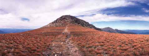
Figure 13.16 Place in the middle of your panorama the faraway point in the scene and avoid subjects in the immediate foreground.
Photographic equipment and techniques
There are many ways to create photographic panoramas, either by using dedicated cameras, special lenses or simply by printing or stitching multiple images together. Digital photography offers an enormous advantage, as you can easily stitch multiple shots in Adobe Photoshop (or other imaging software packages), or better assemble a mosaic of pictures in especially designed software, or even create interactive panorama movies. Formally, panoramic photography is divided into single and multiple frames.
Single-frame panoramas
One way to obtain single-frame panoramas is by using film cameras with rotating (or swing) lenses. The lens rotates around its rear nodal point – from which the back focal length is measured – while a vertical slit exposes a strip of film which is aligned with the optical axis of the lens. Lens and slit scan horizontally across the panoramic scene. Typically, the shots encompass 110°–140° field of view horizontally and 60° vertically, thus the horizontal image size will commonly take up1.5–2.5 the length of a common 35 mm frame (Figure 13.17).Unfortunately, most swing lenses come with a fixed focal length and can focus appropriately at 10 m or more. To shoot subjects which are closer than that use a small aperture to provide big depth of field. However, as the number of shutter speeds in these cameras is limited you might have problems at low light levels.
Rotating panoramic cameras function in a similar way, but in this case it is the camera body that rotates around the front nodal point of the static lens. They are also referred to as slit or scanning cameras. The horizontal panoramic coverage can be up to 360° and in some cases more. A mechanism rotates the camera continuously while the film (which sits on a curved plane) rolls in the opposite direction in such a way that the speed of the film matches the speed with which the image is moving across the image plane. The film is exposed through a thin slit and thus a sharp image is produced throughout.

Figure 13.17 Panoramic cameras rollfilm (left), and 35 mm (right). As shown in plan view the lens and slit of the 35 mm camera form a drum which rotates about a 110°–140° horizontal field of view.

Figure 13.18 Digital rotating panoramic camera which covers 360°. Image reprinted with permission from Roundshot/Seitz Phototechnik.
Digital rotating panoramic cameras (or line cameras) compose 360° full panoramas by scanning line-by-line with a line sensor (Figure 13.18). The principle of image capture is similar to those of a scanner, where a filtered RGB sensor scans the documents linearly. In rotating panoramic cameras the sensor, which typically comprises of 3 linear CCD arrays of approximately 10 000 pixels, moves around a fixed rotation axis. The image size of a 360° panorama depends on the lens used and can reach values between 300 and 1200 mega pixels at high bit-depths. Digital panoramic cameras are often used for producing indoor and outdoor panoramas of large buildings and historical sites.
The results you get when using swing lens and panoramic cameras are without the extreme distortions of lines, which are often seen in extreme wide-angle lenses, but image perspective is unique. You have to level the camera correctly, that is parallel to the subject plane, otherwise you will introduce distortions. By tilting it up or down horizontal lines near the top and bottom of the frame will curve down or up, respectively. When your subject is at close distance horizontal lines will converge at the middle ends of the picture. Consequently, in a scene containing a building at a near distance, even if the camera is flat on, the horizontal building lines will be reproduced curved up together at each end of the frame. On the other hand, a curved subject – such as a long group of people sitting around a concave row of chairs – reproduces as a straight line. Tilting the camera up or down causes vertical lines to converge at the top and bottom of the frame, respectively (Figure 13.19). Saying that, sometimes extreme perspective can be used to give an extremely dramatic viewpoint.

Figure 13.19 Subject shot (left) with a regular 35 mm camera and 28 mm lens, and (right) with a 35 mm panoramic camera and 28 mm lens. If you tilt a panoramic camera up or down, shapes are wildly distorted. Even when you keep it horizontal (bottom right), parallel horizontal lines in the subject reproduce curving together at each end of the picture. To see accurately, curve the page and view close.
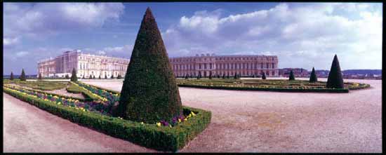
Figure 13.20 With correct choice of viewing angle you can control distortions in the image. Photograph taken with a Widelux wide-angle camera.
A different type of panoramic cameras, with stationary fixed lenses and a flat – as opposed to curved – film plane, is the wide-angle or wide-field camera systems. These are the most common panoramic cameras (Figure 13.20). They come at various image formats, from 2:1 to 4:1 aspect ratios, and may vary significantly in quality and price. Note that the APS format cameras offer single-frame panoramic shots by cropping the frame into a panoramic aspect ratio. Image of true wide-view cameras is relatively distortion free but the panoramic coverage is restricted when compared to swing lens or to rotating cameras. Nevertheless, they are popular for shooting architectural panoramas as they do not cause lines to curve or produce perspective distortions. Another great advantage of this type is the instantaneous exposure of the frame as opposed to the longer, sweeping exposures of other types of panoramic cameras. The use of flash is also not restricted, as it often happens with cameras that only expose one part of the image at a specific moment. Typically, the maximum angle of view with a flat film/sensor camera is about 90°, although lenses with up to 150° can be used. In this latter case you might need to use a neutral density ‘centre’ or ‘spot filter’ in front of your camera’s wide-angle lens to eliminate optical vignetting, which reduces exposure of the film at the edges of your frame, but at the expense of approximately 2 EV. A good tripod will greatly help stability and a spirit level will assist you align the camera plane parallel to the subject plane, thus minimize line convergence.
For digital work, you can use one-shot 360° digital panoramic cameras which use parabolic mirrors and relay lenses to capture the entire view in one frame. With the camera’s software you can then ‘flatten’ the distorted image and create a panorama. Alternatively, especially designed digital camera lens attachments with an optical reflector can be fitted directly or with an adapter to many digital cameras for one-shot 360° panoramic photography. Image quality depends on the quality of the reflectors and can be very impressive.
Multiple-frame panoramas
Most keen photographers carrying conventional cameras have tried to create panoramic imagery by rotating themselves around a fixed point, capture separate fields of the panorama and then stitch the images together. Quality multiple-frame panoramas are created using all kinds of cameras but they require extra apparatus and skill. To create good panoramic images you must accommodate for exposure variations between individual shots, lens and camera tilt related distortions.
A tripod with a panoramic rotating head will help you control camera shake, position and rotation around the nodal point. Levelling errors will produce a curved annular montage, so use a spirit level. Allow a minimum of 10% overlapping between the frames to accommodate for lens geometric distortions seen at the extreme parts of the frame. More overlapping is required if you use a wide-angle lens which distorts larger parts of the frame. Although wide-angle lenses require fewer shots to cover the same view they make things appear smaller and more distant. Try to avoid extremes in lighting between the frames and expose manually, setting up an average exposure taken from the entire panorama. Exposure problems are greater on clear sunny days, as there are plenty of bright highlights and dark shadows. In such days shoot midday to keep the light between frames even, also try to ‘hide’ the view of sun behind large objects, such as buildings, trees, etc. When shooting indoors better avoid shooting windows (Figure 13.21).
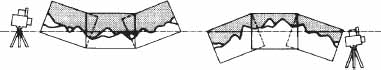
Figure 13.21 Panoramas. When shooting a series of pictures for a join-up panorama, avoid pointing the camera either downwards or upwards, however slightly. Results will have a dished or humped horizon. Instead use a spirit level to help set the camera exactly horizontal. A rising or drop front (e.g. shift lens) then allows you to reposition the horizon higher or lower in the frame if needed.
Before digital photography this good practice was an indispensable element of good-looking panoramic images. Modern digital cameras are often equipped with dedicated software which can stitch images together, correct for uneven lighting and all kinds of distortions and even extrapolate information to match image perspective. The quality of result depends largely on the capabilities of the software, although starting with fewer exposure, distortion and levelling problems is an advantage (Figure 13.22). It is also better to avoid automatic white balance. Various panorama-making software applications are also available that are not attached to specific cameras. Further, the Apple’s Quick Time VR – as well as other analogous software – let you make 360° cylindric panoramas and display them as immersive virtual reality pictures in which the viewer can interactively pan around, look in different directions and zoom in or out by changing the zoom angle. QTVR files can be played back on any computer platform and using any movie player, provided that Quick Time and Quick Time VQ extensions (or plug-ins for viewing from web pages) are installed. Such interactive panoramas can also be constructed using one-shot panoramic techniques.

Figure 13.22 An example of a stitched panoramic photograph. The multiple shots were taken with a Canon 5D camera and a 17 mm lens, attached on a panoramic head.
Stereo photography
Stereo (or 3-D) photography exploits the fact that when a three-dimensional scene is viewed through a pair of eyes – binocular vision – the parallax difference between the two viewpoints makes foreground objects appear in front of different parts of the background. To some extent you ‘see around’ nearby objects. For example, hold your thumb up about 30 cm away. Then, without moving your head, notice where the thumb coincides with some distant wall detail, just using the left, then the right eye. This parallax difference is only one of the main functions the eye employs to sense three-dimensional depth and distance; this is why stereo photography comes with its problems – it does not represent a ‘perfect’ 3-D world. Other functions tend to be differences in scale, tone, focus and in the greater image shift of near objects relative to distant ones when you move your head.
Photographic and viewing equipment and techniques
Stereo cameras are pairs of cameras with matched lenses, linked shutters and diaphragms. The two halves of a stereo camera have their lens centres about 65 mm apart (stereo separation), matching the average separation or interocular distance between a pair of human eyes. This also leaves room for a direct viewfinder between the two. Pictures are exposed in pairs onto 35 mm film, each one being half-frame or 24 mm square format. Frames are often interleaved and so must be sorted and paired up after processing (see Figure 13.23).
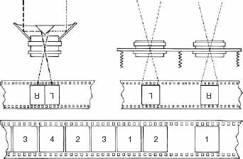
Figure 13.23 How stereo pairs record on 35 mm film. A beam splitter attachment exposes half-frame pictures within the regular format (left). Left-and right-hand versions are correctly located when you turn pictures the correct way up. When you use a stereo camera half-frame images record with two spaces between them. This is filled in with parts of other pairs to save film. Your film winds on two half frames each time, interlinking pairs as shown below.

Figure 13.24 A pair of two Sony DSC-V3 digital cameras mounted together on a CNC milled aluminium mount for stereo photography. The system includes a Sony HVL-F32X flash for stereo photography and is controlled by a LANC Shepherd Pro stereo electronic controller. Image courtesy of Ledametrix.com.
Alternatively you can just pair up two regular cameras – 35 mm SLRs or digital cameras, for example (Figure 13.24). Paired cameras are best used with electric releases, wired in parallel to synchronize shutters and so work with flash or shoot moving subjects. Motorwind is also a helpful feature. Generally speaking, the separation between the two cameras should change proportionally with the distance of the subject from the cameras. When you are shooting stereo photographs, point the cameras at your subject and place a feature in the background in the same position in both left and right shots. Avoid aiming the two cameras directly at the subject, keep them parallel instead. The appropriate stereo separation should produce approximately 7 mm difference in the subject between the two images. For very close subjects use a smaller than 65 mm separation (hypostereoscopy), as normal 65 mm separation gives such extreme parallax difference that your eyes cannot fuse results into one three-dimensional image. For larger than life size images you work using a separation of 65 mm divided by magnification. In opposition, for faraway subjects a larger separation is required (hyperstereoscopy). When shooting landscapes the stereo separation is typically measured in fractions of a metre whereas close-up subjects require a separation in millimetre. Experiment to find the appropriate camera separation that best suits the subject and the equipment you use.
Another approach to stereo photography is to use a stereo attachment, a beam-splitter device which fits over a regular camera’s standard lens, like a lens hood (Figure 13.23). It splits the usual horizontal format picture into a stereo pair of upright half-format pictures. Inside, four front-silvered mirrors redirect the light so that your pictures are taken with viewpoints 65 mm apart. The attachment is best used on an SLR camera, where you can see the effect on the focusing screen. Results can be seen in three dimensions, using a hand viewer of similar design or by projection methods discussed later. A quite different stereo attachment takes the form of a sliding bracket fitted between a tripod and a regular camera. It is designed for making stereo pairs of relatively static subjects – you take one full-frame picture then slide the whole camera quickly 65 mm to one side before taking another.
There are different ways to view each pair of photographs and make them appear as a single three-dimensional picture (stereogram) (Figure 13.25). In all cases it is essential that left-and right-hand side versions are seen by the left and right eyes, respectively. You can use hand viewers for slides or for prints. Alternatively, you can project slides using two projectors to give offset images in the same screen. In this case you need to give your audience spectacles which permit each eye to see one image only. You can achieve this by fitting left or right projectors with colour filters, picking any two rather opposite hues, well separated in the spectrum such as deep green and red or magenta and cyan. Spectacles matching these hues allow the correct image to be seen by each eye, although the 3-D resulting image (anaglyph), even from colour slides, is seen as monochrome. Alternatively you may use pairs of linear polarizing filters for the projectors, orientated orthogonally to each other, and have matching glasses. This arrangement allows showing stereo colour slides in full colours, but your screen must have a metallized (silver) surface so that polarization is unaltered when image light is reflected and reaches the audience. Another way of showing three-dimensional results is by a special parallax stereogram print. This works without needing spectacles but is more suited to mass production. The results are less notable than by other viewing methods.
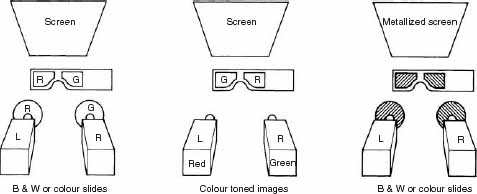
Figure 13.25 Ways of projecting pairs of stereo images, with results encoded so that when looking through spectacles each eye only sees its correct left- or right-hand side picture. Left: deep colour filters over projectors; results look monochrome, even if slides are colour. Centre: black and white images colour toned; results are monochrome. Right: the best arrangement using correctly orientated polarizing filters and metallized screen; images can appear in full colour.
Digital monochrome anaglyphs can be made easily from digital stereo pairs. It suffices to convert an RGB image pair first to greyscale, copy and paste the right image into a new RGB image file of the same size and finally copy and paste the red channel only of the left image into that new image file. The new image’s colour channels will be as follows: the red channel will have the left stereo image and the green and blue channels will have the right stereo image.
A similar technique can be used to create colour digital anaglyphs. This time the entire right RGB image is copied into a new RGB image file and the red channel of the left image replaces the red channel of the new image file. The colour quality of the anaglyph will depend on the colours of the scene but will never be totally faithful to the original. Some colour de-saturation will be needed in the green and more in the blue channels to compensate for the eye sensitivities. Without the 3-D glasses the new image will appear rather dim but will improve substantially when the glasses are put on.
A different viewing technique that also does not require stereo viewing equipment is the free-vision fusion, in which the left-eye and right-eye images are visually merged into a single stereogram. In the crossed-eye free-vision fusion the left eye looks at the right-hand image while the right eye looks at the left-hand image. In the parallel-eye free-vision fusion the centres of the photos must be approximately the same distance as the interocular distance. Motion 3-D or wiggle stereoscopy, on the other hand, relies mainly on the fact that as we move our heads rapidly the changing relationship of objects around us are processed in such a way from our brain to give a 3-D impression. In this stereo viewing method the left and right images of a stereo pair are displayed (by an appropriate animated file or application) alternately so that the ‘wiggling’ result gives a stereo feeling to the viewer.
Special software and freeware to handle stereo pairs is available today to stereo imaging fans. It provides various possibilities for editing and viewing stereo pairs, for example positioning the two images in selected distances for free-vision fusion or creating different hue anaglyphs that match the hues of your viewing glasses.
Applications
Stereo photography is useful wherever three-dimensional information is needed, for measurement, training and education or simply for pictorial effect. It is an important aspect of aerial survey photography, where it allows observing the relative heights of buildings and the general terrain. Modern high-end 3-D imaging is employed today by the computer game and film industries. 3-D is becoming also important to other fields such as molecular modelling, photogrammetry, flight simulation, visualization of multi-dimensional data, architecture and medical imaging such as remote surgery. 3-D scanners are used to record 3-D information (geometric samples on the surface of the subject). The depth information is then reconstructed to create meaningful pictures from two images by corresponding the pixels in the left and right images.
Over the last decade a number of manufacturers offer various 3-D displays technologies for visual stereo presentations. For example, stereo pair-based displays distribute left and right views of a scene to the left and right eyes of the viewer independently and can be viewed either with or without viewing devices. Further, head-mounted displays for 3-D viewing are helmets or glasses that incorporate two small liquid crystal displays or organic liquid crystal displays and magnifying lenses. An offset image is displayed to each eye. This technology is to show stereo films, images or video games. It is also employed in virtual or augmented reality displays (Figure13.26).
‘Hand-made’ image processes
To get something physically different from your ‘normal’ printed or displayed photographic images your can look at the possibilities of light-sensitizing your own choice of artist’s papers, or any other suitable material, or in transferring colour images onto them from instant pictures.
Liquid emulsion
It is possible to mix up your own emulsion from chemicals such as silver nitrate, potassium bromide and gelatine. Preparation is time consuming and often tricky so instead, you can buy containers of ready-to-use gelatine emulsion with which you coat (in the darkness) your chosen base material and allow it to dry before exposing it, using an enlarger and processing it in the normal way. The type of surfaces you can coat include drawing paper, wallpaper, canvas, wood, plaster, most plastics and glass. Try coating three-dimensional objects like egg- or seashells, fragments of stone, ceramic tiles or plates. Since the coating is thin and transparent it takes on all the texture and colour of whatever base material you use. Choose a picture which suits the nature of the unusual base, both in subject matter and visual design. Highly textured materials need simple images (Figure 13.27).

Figure 13.26 This figure illustrates the use of a VisBox-X2 Immersive 3D Display at Valparaiso University, USA. Architecture is one of the areas where the immersive display is used. In this image architectural details are shown to be discussed between Dr. Jeffery Will of the University’s Engineering Department and Jeff Jacobs of Design Organization. The VisBox controls are monitored by the student Mike Steffen.: © 2005 Aran D. Kessler.

Figure 13.27 Example of coating and exposing with ready-made emulsion, here a ceramic tile. (1) The emulsion comes in solid jelly form which you will have to turn it into liquid by warming up the top part of the container in water. (2) For coating use a flat brush and criss-cross your strokes on the material. Then leave it for several hours in darkness until fully dry. (3) Use some test material first under the enlarger to make an exposure series before the final exposure. Once your final result is produced, materials such as ceramic or metal can be sealed over with matt clear varnish to help protect the image.
Emulsion lift
Emulsion lift simply means ‘floating off’ the emulsion layer from a processed Polacolor instant print and repositioning it on a fresh base. During this procedure you can stretch, crease and tear the membrane, or just settle it straight onto a textured or transparent surface. The creases and tears become quite dominant, so you need to consider this feature when planning your shot (Figures 13.28 and 13.30).

Figure 13.28 Emulsion lift technique. Top: Polaroid print soaked for 5 min in hot water begins to frill. Centre: Freed from its backing paper the emulsion membrane can be rolled on to a pencil. Gently agitate it in clean warm water to remove unwanted bits. Bottom: Float emulsion on water surface, withdraw receiving paper from underneath it and draw out with image in contact. Adjust shape with watercolour brush, then tape paper to flat surface to dry out flat.
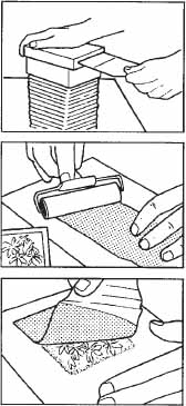
Figure 13.29 Image transfer technique. Top: Slide or transparency on light box is copied on peel-apart Polacolor material. After pulling through the rollers material is only allowed 10 sec before peeling print and negative apart. Centre: Print part discarded, the paper negative is pressed face down on predampened watercolour paper and rolled evenly with ink roller for approximately 1 min. Bottom: Leave 30 sec then gently peel off. Leave to dry. Spot-in any blemishes using watercolours.
Image transfer
This again uses peel-apart instant picture material, but with its processing time curtailed so that the image has only developed on the negative sheet but not yet formed a positive on the receiving sheet. Then you peel the two sheets apart. The original receiving paper is discarded and the negative sheet rolled into tight contact with dampened watercolour paper. After about 1 min you gently peel away the negative, leaving a positive image on the new base, which is left to dry.
Damp paper transferring diffuses your image slightly, but this can be used for effect. ‘Dry’ transfer is more uncertain and difficult than it sounds – it is easy to leave part of the image behind and form pinholes and other minor blemishes (see Figures 13.29 and 13.31). Images with many dark shadows are most likely to leave bits stuck to the negative. Colour balance is also changed because some of the yellow and magenta image dyes in the negative sensitive material will have migrated to the Polaroid receiving paper and been lost. You may therefore have to compensate by shooting with a reddish filter over the lens. For hit-or-miss reasons like these it makes sense to work by copying an existing transparency. You can then repeat yourself easily, making adjustments to timing and physical technique.
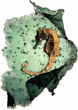
Figure 13.30 Image produced by ‘emulsion lifting’ Polaroid material. Since creases, folds, and frayed edges are inherent in this process plan and use them as an integral part of your picture. This can also be a start point for the creation of composite pictures, provided you let the emulsion dry thoroughly before adding further lifts. By Alastair Laidlaw.

Figure 13.31 An image transfer, using the (processed) negative half of peel-apart instant picture material rolled immediately into contact with water-colour paper. Characteristically, colours become more muted. Your receiving material is best first soaked in distilled water, then blotted off. By Alastair Laidlaw.
SUMMARY
![]() Infrared photography is carried out using infrared monochrome film, which is sensitive up to 900 nm, infrared colour reversal film that gives a mixture of false colours, or with the use of digital cameras, which are naturally sensitive to infrared. Digital cameras often incorporate an infrared blocking filter which partially stops infrared falling on the camera sensor. If the filter is not removable, longer exposure times allow infrared to be recorded. In infrared photography, deep red or infrared, only passing filters are used. Re-set your focusing scale or stop down to provide a large depth of field.
Infrared photography is carried out using infrared monochrome film, which is sensitive up to 900 nm, infrared colour reversal film that gives a mixture of false colours, or with the use of digital cameras, which are naturally sensitive to infrared. Digital cameras often incorporate an infrared blocking filter which partially stops infrared falling on the camera sensor. If the filter is not removable, longer exposure times allow infrared to be recorded. In infrared photography, deep red or infrared, only passing filters are used. Re-set your focusing scale or stop down to provide a large depth of field.
![]() Sunlit living foliage reflects plenty of infrared and thus appears whitish on positive monochrome images, whereas blue skies and water appear black as they mostly absorb infrared. Landscapes and portraits take a strange, dream-like look. Infrared photography is used widely in forensic and medical applications and aerial surveys.
Sunlit living foliage reflects plenty of infrared and thus appears whitish on positive monochrome images, whereas blue skies and water appear black as they mostly absorb infrared. Landscapes and portraits take a strange, dream-like look. Infrared photography is used widely in forensic and medical applications and aerial surveys.
![]() UV photography can be split into UV reflectance and UV fluorescence. In both cases UV sources are used to illuminate the subject. In UV reflectance visible barrier filters are placed in front of the lens to allow only the reflected UV from the subject to be recorded. In UV fluorescence UV barrier filters are used to allow recording of the subject’s fluorescence (occurring mostly in the visible).
UV photography can be split into UV reflectance and UV fluorescence. In both cases UV sources are used to illuminate the subject. In UV reflectance visible barrier filters are placed in front of the lens to allow only the reflected UV from the subject to be recorded. In UV fluorescence UV barrier filters are used to allow recording of the subject’s fluorescence (occurring mostly in the visible).
![]() Much of the UV radiation from the sun is harmful, but most of it is absorbed by the atmosphere. It has the property to penetrate surface layers. This makes UV reflectance recording useful for imaging strong skin pigmentation, cuts and scratches that are no longer visible and the structures of the painting’s surface layers. UV fluorescence recording is useful in crime scene investigations.
Much of the UV radiation from the sun is harmful, but most of it is absorbed by the atmosphere. It has the property to penetrate surface layers. This makes UV reflectance recording useful for imaging strong skin pigmentation, cuts and scratches that are no longer visible and the structures of the painting’s surface layers. UV fluorescence recording is useful in crime scene investigations.
![]() Panoramic photography includes all types of imaging with fields of view wider than the eye, although true panoramas have larger than 2:1 aspect ratios. Complete panoramas cover 360° views. It is suitable for shooting large groups, open landscapes, cityscapes and large interiors.
Panoramic photography includes all types of imaging with fields of view wider than the eye, although true panoramas have larger than 2:1 aspect ratios. Complete panoramas cover 360° views. It is suitable for shooting large groups, open landscapes, cityscapes and large interiors.
![]() Single-frame panoramas are often captured with panoramic cameras that use rotating lenses or rotating bodies. Resulting dramatic perspective is unique – straight lines in the subject may appear straight. Otherwise, the most common single-frame panoramas are shot with wide-field camera systems which are relatively distortion-free but the panoramic coverage is restricted. For digital panoramic work, especially designed digital cameras are used or camera lens attachments with an optical reflector that can be fitted directly, or with the use of an adapter, to many digital cameras for one-shot 360° panoramic photography. They come with software which then ‘flattens’ the distorted image and create a panorama.
Single-frame panoramas are often captured with panoramic cameras that use rotating lenses or rotating bodies. Resulting dramatic perspective is unique – straight lines in the subject may appear straight. Otherwise, the most common single-frame panoramas are shot with wide-field camera systems which are relatively distortion-free but the panoramic coverage is restricted. For digital panoramic work, especially designed digital cameras are used or camera lens attachments with an optical reflector that can be fitted directly, or with the use of an adapter, to many digital cameras for one-shot 360° panoramic photography. They come with software which then ‘flattens’ the distorted image and create a panorama.
![]() Multiple-frame panoramas are created with conventional film or digital cameras, with the aid of a panoramic head, to control camera shake and positioning, and a spirit level for camera levelling, i.e. helps avoiding errors that produce a curved annular montage. Modern digital cameras are often equipped with dedicated software which can stitch images together, correct for uneven lighting and all kinds of distortions and even extrapolate information to match image perspective. Apple’s QTVR lets you make 360° cylindric panoramas and display them as immersive virtual reality pictures.
Multiple-frame panoramas are created with conventional film or digital cameras, with the aid of a panoramic head, to control camera shake and positioning, and a spirit level for camera levelling, i.e. helps avoiding errors that produce a curved annular montage. Modern digital cameras are often equipped with dedicated software which can stitch images together, correct for uneven lighting and all kinds of distortions and even extrapolate information to match image perspective. Apple’s QTVR lets you make 360° cylindric panoramas and display them as immersive virtual reality pictures.
![]() Underwater photography requires waterproof equipment and knowledge of the changes created while imaging inside the water and not in the air. Underwater subjects appear closer and larger than they actually are, due to the greater refraction of the light rays. Water also reduces the intensity and changes the colour content of daylight, thus ultimately a strobe is required for correct colour balance at all depths below 3 m.
Underwater photography requires waterproof equipment and knowledge of the changes created while imaging inside the water and not in the air. Underwater subjects appear closer and larger than they actually are, due to the greater refraction of the light rays. Water also reduces the intensity and changes the colour content of daylight, thus ultimately a strobe is required for correct colour balance at all depths below 3 m.
![]() For underwater photography fit an underwater housing to a regular analogue or
digital camera. Such housings have connectors to attach external flash units and allow the lens to look through a domed port (which is advantageous as it reduces distortions and aberrations), or a flat port. Port shape is a function of lens’s focal length.
For underwater photography fit an underwater housing to a regular analogue or
digital camera. Such housings have connectors to attach external flash units and allow the lens to look through a domed port (which is advantageous as it reduces distortions and aberrations), or a flat port. Port shape is a function of lens’s focal length.
![]() Stereo photography needs capturing pictures in pairs, with viewpoints normally 65 mm apart. Stereo cameras come with matched lenses, linked shutters and diaphragms. However, you can use a regular camera and shift the camera or subject between exposures or use two cameras wired in parallel. You can give hyperseparation (i.e. greater than 65 mm) for very faraway subjects or hyposeparation (i.e. smaller than 65 mm) for very close subjects.
Stereo photography needs capturing pictures in pairs, with viewpoints normally 65 mm apart. Stereo cameras come with matched lenses, linked shutters and diaphragms. However, you can use a regular camera and shift the camera or subject between exposures or use two cameras wired in parallel. You can give hyperseparation (i.e. greater than 65 mm) for very faraway subjects or hyposeparation (i.e. smaller than 65 mm) for very close subjects.
![]() Pairs of pictures are combined to produce a three-dimensional image, which can be viewed using hand viewers, twin projectors and appropriate viewing glasses. Free-vision fusion and wiggle stereoscopy are methods to see 3-D images from stereo pairs without stereo viewing aids. Stereo imaging is used for measurement or pictorial effect. It is employed nowadays by the computer game and film industries and is becoming particularly important in modelling, simulation and medical imaging.
Pairs of pictures are combined to produce a three-dimensional image, which can be viewed using hand viewers, twin projectors and appropriate viewing glasses. Free-vision fusion and wiggle stereoscopy are methods to see 3-D images from stereo pairs without stereo viewing aids. Stereo imaging is used for measurement or pictorial effect. It is employed nowadays by the computer game and film industries and is becoming particularly important in modelling, simulation and medical imaging.
![]() ‘Hand-made’ printing allows you to break away from the regular appearance of photographic prints. Examples include coating liquid silver halide emulsion on selected surfaces, coating your choice of paper with a gum/pigment mixture sensitized with potassium dichromate or use Polaroid material that allow to ‘emulsion lift’ the colour image from the print and membrane it to a different support.
‘Hand-made’ printing allows you to break away from the regular appearance of photographic prints. Examples include coating liquid silver halide emulsion on selected surfaces, coating your choice of paper with a gum/pigment mixture sensitized with potassium dichromate or use Polaroid material that allow to ‘emulsion lift’ the colour image from the print and membrane it to a different support.
PROJECTS
1 Go out on a bright sunny day with your digital camera, a tripod, a filter such as the number 87 or/and 87A Kodak Wratten filters and a filter holder that fits your lens. Try to find a location where there is plenty of foliage and a pond or a lake. Expose your subjects with and without the filters, in the latter case having set your camera to obtain a black and white record. Notice the differences in exposure and the resulting tones in your images.
2 Next time you find yourself in a club, bar or any indoor location lit by deep blue or ‘back lights’ notice the teeth and skin of the people around you. What do you observe?
3 With digital photography it is easy to make spectacular panoramas. Use your digital camera, a tripod and a spirit level. Find a place in the city where there are many roads meeting (e.g. a small roundabout). Place yourself and the camera in the centre of the roundabout. Take multiple shots ensuring plenty of overlapping. Expose manually, after having measured an average exposure from all frames. Using your camera’s software stitch the images together. Examine the result; what would you have done better if you were to repeat the shooting?
4 Next time you go swimming take a small single-use underwater camera. While on the beach try to take a picture of a nearby to your lens object with half the camera’s lens immersed in the shallow water and the other half in the air. What do you notice in the resulting image? Once you are underwater, take some pictures of the same objects (rocks, algae, fish) with and some without flash. Examine the differences.
5 Go on the Internet and type the words ‘stereo photography without glasses’. You will find plenty of links to Internet sites showing stereo pairs that can be viewed with parallel or cross-eyed free-vision fusion. Try to discover the underlying 3-D image by following the given instructions.
6 Next time you want to make a present consider purchasing a small container with liquid emulsion. Coat a mug, a tile or a piece of wood and expose on it your favourite black and white negative. Try to match the texture of the chosen material with the image texture in detail.