
Doug Bradbury
Treadmill Desk
An “active workstation” from a treadmill and Ikea parts.
MATERIALS
Treadmill must have sturdy upright supports and support the iFit Chirp protocol. I used a Sears ProForm 830QT.
Tabletop Ikea Galant
Pull-out keyboard shelf Ikea Summera
Lumber, 2×4, 4' long
Bolts, ⅜"×3", with matching washers and nuts (4)
Cable, stereo, with ⅛" male plug
TOOLS
Screwdrivers
Drill and drill bit
Jigsaw
Ruler
Rotary tool with cutting wheel
Tape masking or packing
A FEW YEARS AGO, WHEN MY SOFTWARE
company was buying its first office furniture, I coveted a $4,500 adjustable-height desk with a treadmill underneath. I thought this would be a good way to change a sedentary job into an active one.
Later, when I saw desk designer Dr. James Levine’s research on non-exercise activity thermogenesis (NEAT), I learned that he’d originally mashed together a treadmill and a laptop desk to test the idea, and he raved about the results. I decided to make my own.
1. Source the parts.
My first step was to acquire a treadmill. I didn’t want to pay retail price for something I was going to tear apart, so I looked to Craigslist (craigslist.com), which was full of people unloading their treadmills. I found a ProForm 830QT (a Sears brand) for only $140. For treadmill specs and reviews, the Treadmill Sensei website (treadmillsensei.com) was a great resource.
My next stop was the discount “as-is” section of Ikea, where I snatched a display-model Galant table, frame, and T-leg combo for $60.
2. Tear everything apart.
I began construction in the way that any good mash-up project begins: by tearing everything apart. I unscrewed and unplugged everything I could find on the treadmill until I was left with just the tread, the upright frame, and the touch-panel control unit (Figure A).

One main control cable ran through a leg of the treadmill from the control panel to the motor below. There was also an audio cable, a cable running to the hand-grip heart rate monitor, and an extra heart rate cable that led to nothing. The idea behind treadmill desks is to walk slowly for long periods of time, rather than to get your heart pounding, so I yanked out all the heart rate cables and sensors.
3. Mount the tabletop.
Prying the rubber handgrips off each side revealed horizontal supports at a good height for the table. So I drilled a hole through the posts and bolted on a 2×4 that was long enough to span the Galant table frame.
After removing the frame from the tabletop, I chose 2 holes on the frame that lined up well with the 2×4, drilled holes through the 2×4, and bolted the frame on top (Figures B and C).


![]() TIP: When cutting through a laminated surface (like most Ikea stuff), stick masking or packing tape over your cut line to prevent the laminate from chipping.
TIP: When cutting through a laminated surface (like most Ikea stuff), stick masking or packing tape over your cut line to prevent the laminate from chipping.
Things looked good except for the 2 upright posts that would prevent the tabletop from being installed. I had 2 options: either cut off the posts or notch out the tabletop. My tools and expertise were better matched to notching the table, so I proceeded to carefully measure and cut the holes with a drill and jigsaw. Then I screwed the tabletop to the frame from below.
4. Reconnect the control panel.
It was time to re-establish control of the treadmill. First, I used a rotary tool to hack away at the plastic enclosure containing the touch panel and circuit boards until I had a box just large enough to house them.
Conveniently, the box had 2 screw holes on the bottom, which I used to mount the box onto a $10 Ikea pull-out keyboard shelf (Summera), which I installed underneath the desktop (Figure D).

This way, I could easily pull the controls out when I needed to start and stop the treadmill or change the speed, then stow them away, to not interfere with walking or typing.
With the touch-panel enclosure mounted on the keyboard tray with its 2 original mounting screws, there wasn’t quite enough slack in the control cable to pull the control display out far enough to see. So I took the cover off the treadmill base and found a way to reroute the control cable inside to free up sufficient slack (Figure E). After replacing the cover, the treadmill desk was complete.

5. Walk and code.
After building the treadmill desk at home, I packed it up and reassembled it in our office, where it continues to draw a lot of attention.
For a total cost of $210, it’s been a great, healthy addition to our office and has succeeded in making my day a more active one. I comfortably type, code, Skype, talk, and do everything else that I did while sitting down. Now I just do it at 1 mph (Figure F).

One problem arose. We often write software in pairs, which helps us work faster and make fewer mistakes. But the treadmill desk only lets one person walk at a time. So we now have a double treadmill desk, custom-built from my design by a manufacturer in Indiana.
Software Upgrade
Being a software craftsman by trade, I soon became dissatisfied with reaching under the desk all the time to change the speed and incline of the treadmill. I had a computer on top of the desk, so why couldn’t I control the treadmill from there?
Fortunately, my treadmill supports the iFit Chirp protocol, which is primarily used to enable a CD player with a workout CD to plug into the treadmill and send control commands in between music tracks.
The documentation on this protocol is sparse, but I found an open source project in C that generated the correct signals. I ported this library to Java and made it real-time. Then using my company’s Limelight GUI framework for Ruby, my apprentice built an attractive user interface to drive the library.
After plugging the computer’s audio output into the treadmill control input, I now had control of the treadmill right on my computer desktop. Instructions for downloading and running this app are at walkncode.com. ![]()
Doug Bradbury is a software craftsman at 8th Light, Inc. who can’t stop at just making great software. You can contact him via email ([email protected]) or Twitter (@dougbradbury). He lives in the Chicago suburbs with his wife, Jen.

Pauric O’Callaghan
Touchdesk
Customize your own integrated workspace.
AS A USER-INTERFACE DESIGNER, MY JOB
is to understand people’s goals and create a design that allows them to focus less on their tools and more on their work. I decided to apply this thinking directly to my own workspace. First I sketched out my basic design idea and defined my requirements, then I prototyped and iterated my design in electronics, software, and wood. The result is the Touchdesk, which I now use every day.
The keyboard and mouse are generalist input devices that enable all commands through the same interface, but the “80/20 rule” observes that we use 20% of features in any application 80% of the time. In my work, common actions require navigating to submenus or remembering multikey, app-specific shortcuts, while seldom-used commands use up dedicated one-button access.
To remedy this, I sketched out a smarter “soft” keyboard that runs on a touchscreen display inlaid into the desk’s wooden top. Icons on the touchscreen offer one-button access to the actions I use most frequently, with the button mappings changing based on the current application. The buttons themselves graphically represent their functions. To zoom in, for example, you touch a magnifying glass icon instead of having to chord something like Ctrl + as you would on a keyboard.
Above the touchscreen, 4 inlaid wooden buttons are hardwired to Copy, Paste, Delete, and Ctrl, 3 commands and a modifier that are common across all applications and which I felt didn’t need to take up virtual keyboard space. To the right of the touchscreen I inlaid a tablet, the preferred pointing device (replacing a mouse) for drawing and design work.
Resistive touchscreen, 4-wire, 6½" or 7" such as part #360-2446-ND ($38) or #BER277-ND ($59) from Digi-Key (digikey.com). I purchased mine on eBay for around $20.
USB gamepad, one-hand keyboard with keyboard mapping software I used the 15-button Belkin Nostromo n52, $75; the current version is the n52te.
Pointing device for computer: tablet or mouse I used a Wacom tablet, but use whatever you like best.
Digital picture frame, 7"
Arduino Mega microcontroller (or Illuminato) part #MKSP5 from Maker Shed (makershed.com), $65. Standard Arduinos don’t have enough inputs; I used an Illuminato, but the newer Mega will also work.
NPN transistors (15) any basic NPN, such as a 2N3904, part #COM-00521 from SparkFun Electronics (sparkfun.com)
Pushbutton switches, mini SPST (6) such as SparkFun #COM-00097
Protoboard or stripboard to make a shield for the Arduino, such as the 3"×4" 1200D epoxy fiber board from Veroboard (veroboard.com). I used a commodity pad-per-hole protoboard, 24×30 holes, 70mm×90mm.
Protoboard or stripboard for mounting 4 of the mini switches, such as Veroboard’s 2"×10" 2000L boards (epoxy or phenolic). I cut a piece (around 8×60 holes) from some stripboard I got from an old lab.
USB hub, 4-port
Wire, 22 gauge insulated, various colors
Wood glue
Wood, 1"×12", 4' long I used pine for prototyping, oak for the final build.
Hardwood slat, ⅛" thick, at least 1½"×2' such as #64823 from Rockler (rockler.com)
Wood screws, 1¼" (4) #8 screws or whatever you have on hand that will work
Wood screws, ½", self-tapping (6) #6 or whatever size will work
Clear polyurethane spray, semigloss
Male breakaway headers (56 pins total) SparkFun #PRT-00117 (2x)
TOOLS
Plunge router with round-over and mortise bits
Drill and drill bits (for wood screws)
Screwdriver
Glue gun and hot glue
Ruler and pencil
Tools I used for prototyping (which you won’t need if you copy my design):
Boarduino Kit Maker Shed #MKAD9, $18
Arduino Mini USB adapter Maker Shed #MKSP3, $20
Plug-in breadboard power supply, 3.3V/5V Maker Shed #MKSF5, $14
Solderless breadboard
USB-TTL serial cable, 5V
I also wanted to make sure the physical desktop had room to accommodate a paper notepad, along with a traditional keyboard (which I inset in wood to match the desk) that could stow away and be brought out for occasional text entry and document writing.
At the start of the project I wrote out a list of all my design requirements and sketched out the physical workspace (Figure A). I recommend this practice for any major project as a way to stay focused on your vision and decrease the chance that you’ll lose interest and shelve it for another day.

System Architecture
Figure B (following page) represents the Touchdesk’s functional architecture, showing how its input and output devices all connect to the computer via a shared USB hub. The touchscreen display has 2 parts: a standard digital picture frame underneath that shows the icons, and a transparent resistive touchscreen on top that reads the finger presses.

The Arduino drives the resistive touchscreen by applying 5 volts across it, alternating between horizontal and vertical. If a point is being touched, the screen will return a voltage between 0V and 5V for each axis, depending linearly on the point’s distance from the screen’s left (with horizontal voltage applied) or bottom (with vertical voltage applied). Pressing the exact center, for example, returns 2.5V for both x and y.
The x and y voltages from the touchscreen run to analog input pins on the Arduino. The Arduino code then maps these coordinates to the button currently displayed at that position and turns on one of its digital output pins to match.
Each button on the touchscreen maps to one of the Arduino’s output pins, which is why this project requires an Arduino Mega or Illuminato; standard Arduinos don’t have enough I/O to support more than a small number of touchscreen keys, and the Touchdesk uses up to 15 inputs: 11 soft keys plus 4 hardwired buttons.
To convert the Arduino outputs into something the computer and my applications can interpret, I used a USB gamepad with 15 keyboard buttons. Pressing a button on the gamepad closes the connection between 2 points on its internal circuit board, so I wired the Arduino to trick the USB keyboard circuitry into thinking the user pressed a key.
Each Arduino output connects up to an NPN transistor on a plug-in Arduino shield PCB that I built, and each transistor connects out to the USB gamepad’s PCB (Figure C). When a normally open transistor on the shield receives a digital HIGH from an Arduino pin, it closes the transistor gate, making the connection between a button’s contact pair. To the computer on the other end of the gamepad’s USB cable, this looks exactly like a key press.

Above the touchscreen, the hardwired Copy, Paste, Delete, and Ctrl buttons connect directly to contact pairs on the gamepad, in parallel with the Arduino-controlled transistors.
The final piece of the puzzle is configuring the gamepad driver software running on the computer to translate incoming key-press signals into the appropriate actions. The Belkin Nostromo n52 has a nice user interface for making these associations, and it can store a unique mapping for each application (Figure D). The driver then automatically switches mappings to match the app that’s currently running. For example, when I press the top left button on the touchscreen while I’m using Photoshop, I get the brush tool, but if I move over to Word, that button summons the highlight tool.

There is one limitation: although the touchscreen’s button mapping changes functionally when I switch applications, I didn’t figure out an automatic way to tell the display which application is running. For switching the button icon arrays to match different applications, I wired 2 pushbutton switches to the picture frame’s Next and Back buttons.
After I began using the Touchdesk, my fingers soon learned the soft button locations for each app, so I don’t generally rely on the icons anymore anyway. But the ability to manually switch screen images lets me bring up the right set when I need to.
Touchscreen Electronics
Four-wire resistive touchscreens are simple: one wire runs to each side, and you use the same wires to both apply voltage and take a reading along each axis. To hook an Arduino up to the screen, you connect one digital I/O pin to each screen wire for applying voltage, plus one analog input pin each to the screen’s top and right-side wires.
I modified a sketch by Marco Nicolato to program the Arduino to read my touchscreen and determine which button is pressed; you can download the code at makeprojects. com/v/27. For these experiments I used an Arduino Diecimila and Boarduino (Figures E and F, previous page), although I knew that this project needed a microcontroller that could support more dedicated outputs. With the digital picture frame, I simply removed its workings from its case.


I built the Arduino shield on a small protoboard, arranging male pin headers to plug into the Arduino and arraying the top with transistors. Then with the USB gamepad, I extracted its circuit board from its case and traced back contact pairs from each physical key location to find places I could solder to. After wiring each transistor on the shield to a contact pair on the gamepad PCB, I hot-glued the gamepad PCB to the shield (Figure G).

To connect the picture frame board, Arduino, USB gamepad board, and tablet to my computer, I used a 4-way USB hub.
Woodwork
“To carve an elephant from a block of marble, remove everything that doesn’t look like an elephant.” This old saw sums up how I made the Touchdesk’s case. I took some wood and cut out sections to fit the internal electronics and keyboard on top.
I built a prototype using soft pine to figure out dimensions and ergonomics (Figure H). This taught me that I needed to use a smaller tablet and align the touchscreen with my left hand (I’m right-handed) rather than my face.

![]() CAUTION: Routers are powerful tools that can easily run through the wrong part of the wood, your fingers, or both. Take care and time with them, and practice with a prototype before working on the final design.
CAUTION: Routers are powerful tools that can easily run through the wrong part of the wood, your fingers, or both. Take care and time with them, and practice with a prototype before working on the final design.
For the final design, I glued and screwed together a 2-layer case out of 1"-thick oak board. I carved the bottom board with a plunge router to resemble a tray. I carved the top layer to match, creating a hollow cavity for the electronics.
Then I marked and cut a hole to fit the touchscreen components, which I hot-glued to the inside of the case. For the tablet, which is thin, I used the plunge router to carve an indentation just deep enough to let it sit flush with the desk’s top surface. Figure I shows the final woodwork, and Figure J shows the case with electronic components placed.


Physical Buttons
Above the touchscreen I cut a hole for the 4 hardwired wooden buttons (Copy, Paste, Delete, and Ctrl). These buttons consist of thin, flexible, hardwood slats with pushbutton mini switches on stripboard (screwed to the bottom board underneath) that are wired via a pin header to the Arduino shield (Figure K).
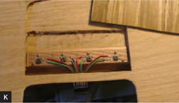
By carrying 4 very common functions, these wooden buttons reduce wear and tear on the touchscreen and add a nice aesthetic to the overall design.
After wiring the 2 pushbutton switches to the digital picture frame’s Next and Back button contacts (for changing the touchscreen icons), I hot-glued them under the desktop along the left edge, just behind the touchscreen (Figure L, upper right).


Final Design Recursion
Finally, with the software stable and the wood finished with clear polyurethane, I used the Touchdesk itself to complete its own design. On the Touchdesk, I created the touchscreen icon array images, which I saved onto an SD card and plugged into the digital picture frame.
Touchdesk 2
Having used the Touchdesk for more than a year now, I’ve compiled a list of improvements for the next version. One problem is that the heat from all the electronics inside the case dried and shrank the wood, causing the resistive screen to ripple and warp. I had to remove the picture frame and reglue in the resistive screen.
Again, the main technical limitation is my having to manually change the images on the digital picture frame to match the application on-screen. It’s a small issue, but I would like to find a way to get that information from the computer to the display.
With that said, the exercise of building my own input device and integrated workspace gave me a better understanding of ergonomics and touchscreen technology and some good coding experience. ![]()
![]() Download the Arduino code file touch_ read.pde at makeprojects.com/v/27.
Download the Arduino code file touch_ read.pde at makeprojects.com/v/27.
Pauric O’Callaghan ([email protected]) is a user-interface designer by day and a carpenter/maker/hacker/kitesurfer by night.