Chapter 3. Databases on Kubernetes the Hard Way
As we discussed in Chapter 1, Kubernetes was designed for stateless workloads. A corollary to this is that stateless workloads are what Kubernetes does best. Because of this, some have argued that you shouldn’t try to run stateful workloads on Kubernetes, and you may hear various recommendations about what you should do instead: “use a managed service”, or “leave data in legacy databases in your on-premises data center”, or perhaps even “run your databases in the cloud, but in traditional VMs instead of containers.”
While these recommendations are still viable options, one of our main goals in this book is to demonstrate that running data infrastructure in Kubernetes has become not only a viable option, but a preferred option. In his article, A Case for Databases on Kubernetes from a Former Skeptic, Chris Bradford describes his journey from being skeptical of running any stateful workload in Kubernetes, to grudging acceptance of running data infrastructure on Kubernetes for development and test workloads, to enthusiastic evangelism around deploying databases on K8s in production. This journey is typical of many in the Data on Kubernetes community. By the middle of 2020, Boris Kurktchiev was able to cite a growing consensus that managing stateful workloads on Kubernetes had reached a point of viability, and even maturity, in his article 3 Reasons to Bring Stateful Applications to Kubernetes.
How did this change come about? Over the past several years, the Kubernetes community has shifted focus toward adding features that support the ability to manage state in a cloud-native way on Kubernetes. The storage elements represent a big part of this shift we introduced in the previous chapter, including the Kubernetes PersistentVolume subsystem and the adoption of the Container Storage Interface. In this chapter, we’ll complete this part of the story by looking at Kubernetes resources for building stateful applications on top of this storage foundation. We’ll focus in particular on a specific type of stateful application: data infrastructure.
The Hard Way
The phrase “doing it the hard way” has come to be associated with avoiding the easy option in favor of putting in the detailed work required to accomplish a result that will have lasting significance. Throughout history, pioneers of all persuasions are well known for taking pride in having made the sacrifice of blood, sweat, and tears that make life just that little bit more bearable for the generations that follow. These elders are often heard to lament when their proteges fail to comprehend the depth of what they had to go through.
In the tech world it’s no different. While new innovations such as APIs and “no code” environments have massive potential to grow a new crop of developers worldwide, it is still the case that a deeper understanding of the underlying technology is required in order to manage highly available and secure systems at worldwide scale. It’s when things go wrong that this detailed knowledge proves its worth. This is why many of us who are software developers and never touch a physical server in our day jobs gain so much from building our own PC by wiring chips and boards by hand. It’s also one of the hidden benefits of serving as informal IT consultants for our friends and family.
For the Kubernetes community, of course, “the hard way” has an even more specific connotation. Google engineer Kelsey Hightower’s Kubernetes the Hard Way has become a sort of rite of passage for those who want a deeper understanding of the elements that make up a Kubernetes cluster. This popular tutorial walks you through downloading, installing, and configuring each of the components that make up the Kubernetes control plane. The result is a working Kubernetes cluster, which, although not suitable for deploying a production workload, is certainly functional enough for development and learning. The appeal of the approach is that all of the instructions are typed by hand instead of downloading a bunch of scripts that do everything for you, so that you understand what is happening at each step.
In this chapter, we’ll emulate this approach and walk you through deploying some example data infrastructure the hard way ourselves. Along the way, we’ll get more hands-on experience with the storage resources you learned about in Chapter 2, and we’ll introduce additional Kubernetes resource types for managing compute and network to complete the “Compute, Network, Storage” triad we introduced in Chapter 1. Are you ready to get your hands dirty? Let’s go!
Warning
Warning: Examples are Not Production-Grade
The examples we present in this chapter are primarily for introducing new elements of the Kubernetes API and are not intended to represent deployments we’d recommend running in production. We’ll make sure to highlight where there are gaps so that we can demonstrate how to fill them in upcoming chapters.
Prerequisites for running data infrastructure on Kubernetes
To follow along with the examples in this chapter, you’ll want to have a Kubernetes cluster to work on. If you’ve never tried it before, perhaps you’ll want to build a cluster using the Kubernetes the Hard Way instructions, and then use that same cluster to add data infrastructure the hard way as well. You could also use a simple desktop K8s as well, since we won’t be using a large amount of resources. If you’re using a shared cluster, you might want to install these examples in their own namespace to isolate them from the work of others.
kubectl config set-context --current --namespace=<insert-namespace-name-here>
You’ll also need to make sure you have a StorageClass in your cluster. If you’re starting from a cluster built the hard way, you won’t have one. You may want to follow the instructions in the section StorageClasses for installing a simple StorageClass and provisioner that expose local storage (source code).
You’ll want to use a StorageClass that supports a volumeBindingMode of WaitForFirstConsumer. This gives Kubernetes the flexibility to defer provisioning storage until we need it. This behavior is generally preferred for production deployments, so you might as well start getting in the habit.
Running MySQL on Kubernetes
First, let’s start with a super simple example. MySQL is one of the most widely used relational databases due to its reliability and usability. For this example we’ll build on the MySQL tutorial in the official Kubernetes documentation, with a couple of twists. You can find the source code used in this section at Deploying MySQL Example - Data on Kubernetes the Hard Way. The tutorial includes two Kubernetes deployments: one to run MySQL pod, and another to run a sample client, in this case Wordpress. This configuration is shown in Figure 3-1.

Figure 3-1. Sample Kubernetes Deployment of MySQL
In this example, we see that there is a PersistentVolumeClaim for each pod. For the purposes of this example, we’ll assume these claims are satisfied by a single volume provided by the default StorageClass. You’ll also notice that each pod is shown as part of a ReplicaSet and that there is a service exposed for the MySQL database. Let’s take a pause and introduce these concepts.
ReplicaSets
Production application deployments on Kubernetes do not typically deploy individual pods, because an individual pod could easily be lost when the node disappears. Instead, pods are typically deployed in the context of a Kubernetes resource that manages their lifecycle. ReplicaSet is one of these resources, and the other is StatefulSet, which we’ll look at later in the chapter.
The purpose of a ReplicaSet (RS) is to ensure that a specified number of replicas of a given pod are kept running at any given time. As pods are destroyed, others are created to replace them in order to satisfy the desired number of replicas. A ReplicaSet is defined by a pod template, a number of replicas, and a selector. The pod template defines a specification for pods that will be managed by the ReplicaSet, similar to what we saw for individual pods created in the examples in Chapter 2. The number of replicas can be 0 or more. The selector identifies pods that are part of the ReplicaSet.
Let’s look at a portion of an example definition of a ReplicaSet for the Wordpress application shown in Figure 3-1:
apiVersion: apps/v1
kind: ReplicaSet
metadata:
  name: wordpress-mysql
  labels:
    app: wordpress
spec:
  replicas: 1
  selector:
    matchLabels:
      app: wordpress
      tier: mysql
  template:
    metadata:
      labels:
        app: wordpress
        tier: mysql
    spec:
      containers:
      - image: mysql:5.6
        name: mysql
        ...
A ReplicaSet is responsible for creating or deleting pods in order to meet the specified number of replicas. You can scale the size of a RS up or down by changing this value. The pod template is used when creating new pods. Pods that are managed by a ReplicaSet contain a reference to the RS in their metadata.ownerReferences field. A ReplicaSet can actually take responsibility for managing a pod that it did not create if the selector matches and the pod does not reference another owner. This behavior of a ReplicaSet is known as acquiring a pod.
You might be wondering why we didn’t provide a full definition of a ReplicaSet above. As it turns out, most application developers do not end up using ReplicaSets directly, because Kubernetes provides another resource type that manages ReplicaSets declaratively: Deployments.
Warning
Warning: Define ReplicaSet selectors carefully
If you do create ReplicaSets directly, make sure that the selector you use is unique and does not match any bare pods that you do not intend to be acquired. It is possible that pods that do not match the pod template can be acquired if the selectors match.
For more information about managing the lifecycle of ReplicaSets and the pods they manage, see the Kubernetes documentation.
Deployments
A Kubernetes Deployment is a resource which builds on top of ReplicaSets with additional features for lifecycle management, including the ability to rollout new versions and rollback to previous versions. As shown in Figure 3-2, creating a Deployment results in the creation of a ReplicaSet as well.

Figure 3-2. Deployments and ReplicaSets
This figure highlights that ReplicaSets (and therefore the Deployments that manage them) operate on cloned replicas of pods, meaning that the definitions of the pods are the same, even down to the level of PersistentVolumeClaims. The definition of a ReplicaSet references a single PVC that is provided to it, and there is no mechanism provided to clone the PVC definition for additional pods. For this reason, Deployments and ReplicaSets are not a good choice if your intent is that each pod have access to its own dedicated storage.
Deployments are a good choice if your application pods do not need access to storage, or if your intent is that they access the same piece of storage. However, the cases where this would be desirable are pretty rare, since you likely don’t want a situation in which you could have multiple simultaneous writers to the same storage.
Let’s create an example Deployment. First, create a secret that will represent the database password (substitute in whatever string you want for the password):
kubectl create secret generic mysql-root-password --from-literal=password=<your password>
Next, create a PVC that represents the storage that the database can use (source code). A single PVC is sufficient in this case since you are creating a single node. This should work as long as you have an appropriate storage class as referenced earlier.
apiVersion: v1
kind: PersistentVolumeClaim
metadata:
  name: mysql-pv-claim
  labels:
    app: wordpress
spec:
  accessModes:
    - ReadWriteOnce
  resources:
    requests:
      storage: 1Gi
Next, create a Deployment with a pod spec that runs MySQL (source code). Note that it includes a reference to the PVC you just created as well as the Secret containing the root password for the database.
apiVersion: apps/v1
kind: Deployment
metadata:
  name: wordpress-mysql
  labels:
    app: wordpress
spec:
  selector:
    matchLabels:
      app: wordpress
      tier: mysql
  strategy:
    type: Recreate
  template:
    metadata:
      labels:
        app: wordpress
        tier: mysql
    spec:
      containers:
      - image: mysql:5.7
        name: mysql
        env:
        - name: MYSQL_ROOT_PASSWORD
          valueFrom:
            secretKeyRef:
              name: mysql-root-password
              key: password
        ports:
        - containerPort: 3306
          name: mysql
        volumeMounts:
        - name: mysql-persistent-storage
          mountPath: /var/lib/mysql
      volumes:
      - name: mysql-persistent-storage
        persistentVolumeClaim:
          claimName: mysql-pv-claim
There are a couple of interesting things to note about this Deployment’s specification.
-
First, note that the Deployment has a Recreate strategy. This refers to how the Deployment handles the replacement of pods when the pod template is updated, and we’ll discuss this shortly.
-
Next, note under the pod template that the password is passed to the pod as an environment variable extracted from via the secret you created above. Overriding the default password is an important aspect of securing any database deployment.
-
Note also that a single port is exposed on the MySQL image for database access, since this is a relatively simple example. In other samples in this book we’ll see cases of pods that expose additional ports for administrative operations, metrics collection, and more. The fact that access is disabled by default is a great feature of Kubernetes.
-
The MySQL image mounts a volume for its persistent storage using the PVC defined above.
-
Finally, note that the number of replicas was not provided in the specification. This means that the default value of 1 will be used.
After applying the configuration above, try using a command like kubectl get deployments,rs,pods to check and see the items that Kubernetes created for you. You’ll notice a single ReplicaSet named after the deployment that includes a random string, for example: wordpress-mysql-655c8d9c54. The pod’s name references the name of the ReplicaSet, adding some additional random characters, for example: wordpress-mysql-655c8d9c54-tgswd. These names provide a quick way to identify the relationships between these resources.
Here are a few of the actions that a Deployment takes to manage the lifecycle of ReplicaSets. In keeping with Kubernetes’ emphasis on declarative operations, most of these are triggered by updating the specification of the Deployment:
- Initial rollout
-
When you create a Deployment, Kubernetes uses the specification you provide to create a ReplicaSet. The process of creating this ReplicaSet and its pods is known as a rollout. A rollout is also performed as part of a rolling update, as described below.
- Scaling up or down
-
When you update a Deployment to change the number of replicas, the underlying ReplicaSet is scaled up or down accordingly.
- Rolling update
-
When you update the Deployment’s pod template, for example by specifying a different container image for the pod, Kubernetes creates a new ReplicaSet based on the new pod template. The way that Kubernetes manages the transition between the old and new ReplicaSets is described by the Deployment’s
spec.strategyproperty, which defaults to a value calledRollingUpdate. In a rolling update, the new ReplicaSet is slowly scaled up by creating pods conforming to the new template, as the number of pods in the existing ReplicaSet is scaled down. During this transition, the Deployment enforces a maximum and minimum number of pods, expressed as percentages, as set by thespec.strategy.rollingupdate.maxSurgeandmaxUnavailableproperties. Each of these values default to 25%. - Recreate update
-
The other strategy option for use when you update the pod template is Recreate. This is the option that was set in the Deployment above. With this option, the existing ReplicaSet is terminated immediately before the new ReplicaSet is created. This strategy is useful for development environments since it completes the update more quickly, whereas
RollingUpdateis more suitable for production environments since it emphasises high availability. - Rollback update
-
It is possible that in creating or updating a Deployment you could introduce an error, for example by updating a container image in a pod with a version that contains a bug. In this case the pods managed by the Deployment might not even initialize fully. You can detect these types of errors using commands such as
kubectl rollout status. Kubernetes provides a series of operations for managing the history of rollouts of a Deployment. You can access these viakubectlcommands such askubectl rollout history, which provides a numbered history of rollouts for a deployment, andkubectl rolloutundo, which reverts a Deployment to the previous rollout. You can also undo to a specific rollout version with the--to-versionoption. Because kubectl supports rollouts for other resource types we’ll cover below (StatefulSets and DaemonSets), you’ll need to include the resource type and name when using these commands, for example:kubectl rollout history deployment/wordpress-mysql
Which produces output such as:
deployment.apps/wordpress-mysql
REVISION  CHANGE-CAUSE
1         <none>
As you can see, Kubernetes Deployments provide some sophisticated behaviors for managing the lifecycle of a set of cloned pods. You can test out these lifecycle operations (other than rollback) by changing the Deployment’s YAML specification and re-applying it. Try scaling the number of replicas to 2 and back again, or using a different MySQL image. After updating the Deployment, you can use a command like
kubectldescribe deploymentwordpress-mysqlto observe the events that Kubernetes initiates to bring your Deployment to your desired state.
There are other options available for Deployments which we don’t have space to go into here, for example, how to specify what Kubernetes does if you attempt an update that fails. For a more in-depth explanation of the behavior of Deployments, see the Kubernetes documentation.
Services
In the steps above, you’ve created a PVC to specify the storage needs of the database, a Secret to provide administrator credentials, and a Deployment to manage the lifecycle of a single MySQL pod. Now that you have a running database, you’ll want to make it accessible to applications. In our scheme of compute, network, and storage that we introduced in Chapter 1, this is the networking part.
Kubernetes Services are the primitive that we need to use to expose access to our database as a network service. A Service provides an abstraction for a group of pods running behind it. In the case of a single MySQL node as in this example, you might wonder why we’d bother creating this abstraction. One key feature that a Service supports is to provide a consistently named endpoint that doesn’t change. You don’t want to be in a situation of having to update your clients whenever the database pod is restarted and gets a new IP address. You can create a Service for accessing MySQL using a YAML configuration like this (source code):
apiVersion: v1
kind: Service
metadata:
  name: wordpress-mysql
  labels:
    app: wordpress
spec:
  ports:
    - port: 3306
  selector:
    app: wordpress
    tier: mysql
  clusterIP: None
Here are a couple of things to note about this configuration:
-
First, this configuration specifies a port that is exposed on the Service: 3306. In defining a service there are actually two ports involved: the port exposed to clients of the Service, and the
targetPortexposed by the underlying pods that the Service is fronting. Since you haven’t specified atargetPort, it defaults to the port value. -
Second, the selector defines what pods the Service will direct traffic to. In this configuration, there will only be a single MySQL pod managed by the Deployment, and that’s just fine.
-
Finally, if you have worked with Kubernetes Services before, you may note that there is no
serviceTypedefined for this service, which means that it is of the default type, known asClusterIP. Furthermore, since theclusterIPproperty is set to None, this is what is known as a headless service, that is, a service where the service’s DNS name is mapped directly to the IP addresses of the selected pods.
Kubernetes supports several types of services to address different use cases, which are shown in Figure 3-3. We’ll introduce them briefly here in order to highlight their applicability to data infrastructure:
- ClusterIP Service
-
This type of Service is exposed on an IP address that is only accessible from within the Kubernetes cluster. This is the type of service that you’ll see used most often for data infrastructure such as databases in Kubernetes, especially headless services, since this infrastructure is typically deployed in Kubernetes alongside the application which uses it.
- NodePort Service
-
A NodePort Service is exposed externally to the cluster on the IP address of each worker node. A ClusterIP service is also created internally, to which the NodePort routes traffic. You can allow Kubernetes to select what external port is used, or specify the one you desire using the NodePort property. NodePort services are most suitable for development environments, when you need to debug what is happening on a specific instance of a data infrastructure application.
- LoadBalancer
-
LoadBalancer services represent a request from the Kubernetes runtime to set up a load balancer provided by the underlying cloud provider. For example, on Amazon’s Elastic Kubernetes Service (EKS), requesting a LoadBalancer service causes an instance of an Elastic Load Balancer (ELB) to be created. Usage of LoadBalancers in front of multi-node data infrastructure deployments is typically not required, as these data technologies often have their own approaches for distributing load. For example, Apache Cassandra drivers are aware of the topology of a Cassandra cluster and provide load balancing features to client applications, eliminating the need for a load balancer.
- ExternalName Service
-
An ExternalName Service is typically used to represent access to a service that is outside your cluster, for example a database that is running externally to Kubernetes. An ExternalName service does not have a selector as it is not mapping to any pods. Instead, it maps the Service name to a CNAME record. For example, if you create a
my-external-databaseservice with anexternalNameofdatabase.mydomain.com, references in your application pods to my-external-database will be mapped todatabase.mydomain.com.
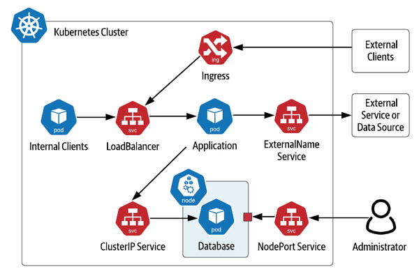
Figure 3-3. Kubernetes Service Types
Note also the inclusion of Ingress in the figure. While Kubernetes Ingress is not a type of Service, it is related. An Ingress is used to provide access to Kubernetes services from outside the cluster, typically via HTTP. Multiple Ingress implementations are available, including Nginx, Traefik, Ambassador (based on Envoy) and others. Ingress implementations typically provide features including SSL termination and load balancing, even across multiple different Kubernetes Services. As with LoadBalancer Services, Ingresses are more typically used at the application tier.
Accessing MySQL
Now that you have deployed the database, you’re ready to deploy an application that uses it - the Wordpress server.
First, the server will need its own PVC. This helps illustrate that there are cases of applications which leverage storage directly, perhaps for storing files, and applications that use data infrastructure, and applications that do both. You can make a small request since this is just for demonstration purposes (source code):
apiVersion: v1
kind: PersistentVolumeClaim
metadata:
  name: wp-pv-claim
  labels:
    app: wordpress
spec:
  accessModes:
    - ReadWriteOnce
  resources:
    requests:
      storage: 1Gi
Next, create a Deployment for a single Wordpress node (source code):
apiVersion: apps/v1
kind: Deployment
metadata:
  name: wordpress
  labels:
    app: wordpress
spec:
  selector:
    matchLabels:
      app: wordpress
      tier: frontend
  strategy:
    type: Recreate
  template:
    metadata:
      labels:
        app: wordpress
        tier: frontend
    spec:
      containers:
      - image: wordpress:4.8-apache
        name: wordpress
        env:
        - name: WORDPRESS_DB_HOST
          value: wordpress-mysql
        - name: WORDPRESS_DB_PASSWORD
          valueFrom:
            secretKeyRef:
              name: mysql-root-password
              key: password
        ports:
        - containerPort: 80
          name: wordpress
        volumeMounts:
        - name: wordpress-persistent-storage
          mountPath: /var/www/html
      volumes:
      - name: wordpress-persistent-storage
        persistentVolumeClaim:
          claimName: wp-pv-claim
Notice that the database host and password for accessing MySQL are passed to Wordpress as environment variables. The value of the host is the name of the service you created for MySQL above. This is all that is needed for the database connection to be routed to your MySQL instance. The value for the password is extracted from the secret, similar to the configuration of the MySQL deployment above.
You’ll also notice that Wordpress exposes an HTTP interface at port 80, so let’s create a service to expose the Wordpress server (source code):
apiVersion: v1
kind: Service
metadata:
  name: wordpress
  labels:
    app: wordpress
spec:
  ports:
    - port: 80
  selector:
    app: wordpress
    tier: frontend
  type: LoadBalancer
Note that the service is of type LoadBalancer, which should make it fairly simple to access from your local machine. Execute the command kubectl get services to get the load balancer’s IP address, then you can open the Wordpress instance in your browser with the URL http://<ip>. Try logging in and creating some pages.
Note
Note: Accessing Services from Kubernetes distributions
The exact details of accessing services will depending on the Kubernetes distribution you are using and whether you’re deploying apps in production, or just testing something quickly like we’re doing here. If you’re using a desktop Kubernetes distributions, you may wish to use a NodePort service instead of LoadBalancer for simplicity. You can also consult the documentation for specific instructions on accessing services, such as those provided for Minikube or K3d.
When you’re done experimenting with your Wordpress instance, you can clean up the resources specified in the configuration files you’ve used in the local directory using the command, including the data stored in your PersistentVolumeClaim:
kubectl delete -k ./
At this point, you might be feeling like this was relatively easy, despite our claims of doing things “the hard way”. And in a sense, you’d be right. So far, we’ve deployed a single node of a simple database with sane defaults that we didn’t have to spend much time configuring. Creating a single node is of course fine if your application is only going to store a small amount of data. Is that all there is to deploying databases on Kubernetes? Of course not! Now that we’ve introduced a few of the basic Kubernetes resources via this simple database deployment, it’s time to step up the complexity a bit. Let’s get down to business!
Running Apache Cassandra on Kubernetes
In this section we’ll look at running a multi-node database on Kubernetes using Apache Cassandra. Cassandra is a NoSQL database first developed at Facebook that became a top-level project of the Apache Software Foundation in 2010. Cassandra is an operational database that provides a tabular data model, and its Cassandra Query Language (CQL) is similar to SQL.
Cassandra is a database designed for the cloud, as it scales horizontally by adding nodes, where each node is a peer. This decentralized design has been proven to have near-linear scalability. Cassandra supports high availability by storing multiple copies of data or replicas, including logic to distribute those replicas across multiple datacenters and cloud regions. Cassandra is built on similar principles to Kubernetes in that it is designed to detect failures and continue operating while the system can recover to its intended state in the background. All of these features make Cassandra an excellent fit for deploying on Kubernetes.
In order to discuss how this deployment works, it’s helpful to understand Cassandra’s approach to distributing data from two different perspectives: physical and logical. Borrowing some of the visuals from Cassandra: The Definitive Guide, you can see these perspectives in Figure 3-4. From a physical perspective, Cassandra nodes (not to be confused with Kubernetes worker nodes) are organized using concepts called racks and datacenters. While the terms betray Cassandra’s origins when on-premise data centers were the dominant way software was deployed in the mid 2000s, they can be flexibly applied. In cloud deployments, racks often represent an availability zone, while datacenters represent a cloud region. However these are represented, the important part is that they represent physically separate failure domains. Cassandra uses awareness of this topology to make sure that it stores replicas in multiple physical locations to maximize availability of your data in the event of failures, whether those failures are a single machine, a rack of servers, an availability zone, or an entire region.
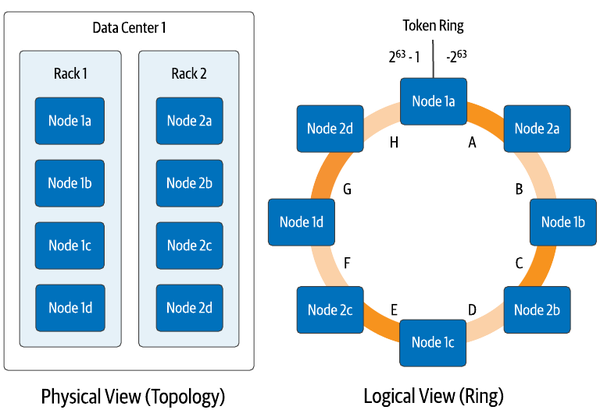
Figure 3-4. Physical and Logical Views of Cassandra’s Distributed Architecture
The logical view helps us understand how Cassandra determines what data will be placed on each node. Each row of data in Cassandra is identified by a primary key, which consists of one or more partition key columns which are used to allocate data across nodes, as well as optional clustering columns, which can be used to organize multiple rows of data within a partition for efficient access. Each write in Cassandra (and most reads) reference a specific partition by providing the partition key values, which Cassandra hashes together to produce a value known as a token, which is a value between −263 and 263−1. Cassandra assigns each of its nodes responsibility for one or more token ranges (shown as a single range per node in Figure 3-4 for simplicity). The physical topology is taken into account in the assignment of token ranges in order to ensure copies of your data are distributed across racks and datacenters.
Now we’re ready to consider how Cassandra maps onto Kubernetes. It’s important to consider two implications of Cassandra’s architecture:
- Statefulness
-
Each Cassandra node has state that it is responsible for maintaining. Cassandra has mechanisms for replacing a node by streaming data from other replicas to a new node, which means that a configuration in which nodes use local ephemeral storage is possible, at the cost of longer startup time. However, it’s more common to configure each Cassandra node to use persistent storage. In either case, each Cassandra node needs to have its own unique PersistentVolumeClaim.
- Identity
-
Although each Cassandra node is the same in terms of its code, configuration, and functionality in a fully peer-to-peer architecture, the nodes are different in terms of their actual role. Each node has an identity in terms of where it fits in the topology of datacenters and racks, and its assigned token ranges.
These requirements for identity and an association with a specific PersistentVolumeClaim present some challenges for Deployments and ReplicaSets that they weren’t designed to handle. Starting early in Kubernetes’ existence, there was an awareness that another mechanism was needed to manage stateful workloads like Cassandra.
StatefulSets
Kubernetes began providing a resource to manage stateful workloads with the alpha release of PetSets in the 1.3 release. This capability has matured over time and is now known as StatefulSets (see: Sidebar: Are Your Stateful Workloads Pets or Cattle? below). A StatefulSet has some similarities to a ReplicaSet in that it is responsible for managing the lifecycle of a set of pods, but the way in which it goes about this management has some significant differences. In order to address the needs of stateful applications, like those of Cassandra like those listed above, StatefulSets demonstrate the following key properties:
- Stable identity for pods
-
First, StatefulSets provide a stable name and network identity for pods. Each pod is assigned a name based on the name of the StatefulSet, plus an ordinal number. For example, a StatefulSet called
cassandrawould have pods namedcassandra-1,cassandra-2,cassandra-3, and so on, as shown in Figure 3-5. These are stable names, so if a pod is lost for some reason and needs replacing, the replacement will have the same name, even if it is started on a different worker node. Each pod’s name is set as it’s hostname, so if you create a headless service, you can actually address individual pods as needed, for example:cassandra-1.cqlservice.default.svc.cluster.local. We’ll discuss more about running Kubernetes Services for Cassandra later in this chapter in Accessing Cassandra.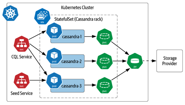
Figure 3-5. Sample Deployment of Cassandra on Kubernetes with StatefulSets
- Ordered lifecycle management
-
StatefulSets provide predictable behaviors for managing the lifecycle of pods. When scaling up the number of pods in a StatefulSet, new pods are added according to the next available number. For example, expanding the StatefulSet in Figure 3-5 would cause the creation of pods such as
cassandra-4andcassandra-5. Scaling down has the reverse behavior, as the pods with the highest ordinal numbers are deleted first. This predictability simplifies management, for example by making it obvious which nodes should be backed up before reducing cluster size. - Persistent disks
-
Unlike ReplicaSets, which create a single PersistentVolumeClaim shared across all of their pods, StatefulSets create a PVC associated with each pod. If a pod in a StatefulSet is replaced, the replacement pod is bound to the PVC which has the state it is replacing. Replacement could occur because of a pod failing or the scheduler choosing to run a pod on another node in order to balance the load. For a database like Cassandra, this enables quick recovery when a Cassandra node is lost, as the replacement node can recover its state immediately from the associated PersistentVolume rather than needing to have data streamed from other replicas.
Warning
Warning: Managing data replication
When planning your application deployment, make sure you consider whether data is being replicated at the data tier or the storage tier. A distributed database like Cassandra manages replication itself, storing copies of your data on multiple nodes according to the replication factor you request, typically 3 per Cassandra datacenter. The storage provider you select may also offer replication. If the Kubernetes volume for each Cassandra pod has 3 replicas, you could end up storing 9 copies of your data. While this certainly promotes high data survivability, this might cost more than you intend.
Defining StatefulSets
Now that you’ve learned a bit about StatefulSets, let’s examine how they can be used to run Cassandra. You’ll configure a simple 3-node cluster the “hard way” using a Kubernetes StatefulSet to represent a single Cassandra datacenter containing a single rack. While this example was inspired by the Cassandra tutorial in the Kubernetes documentation, it does differ from the tutorial in a few respects. The source code used in this section is located at Deploying Cassandra Example - Data on Kubernetes the Hard Way. This approximates the configuration shown in Figure 3-5.
To set up a Cassandra cluster in Kubernetes, you’ll first need a headless service. This service represents the “CQL Service” shown in Figure 3-5, providing an endpoint that clients can use to obtain addresses of all the Cassandra nodes in the StatefulSet (source code):
apiVersion: v1
kind: Service
metadata:
  labels:
    app: cassandra
  name: cassandra
spec:
  clusterIP: None
  ports:
  - port: 9042
  selector:
    app: cassandra
You’ll reference this service in the definition of a StatefulSet which will manage your Cassandra nodes (source code). Rather than applying this configuration immediately, you may want to wait until after we do some quick explanations below. The configuration looks like this:
apiVersion: apps/v1
kind: StatefulSet
metadata:
  name: cassandra
  labels:
    app: cassandra
spec:
  serviceName: cassandra
  replicas: 3
  podManagementPolicy: OrderedReady
  updateStrategy: RollingUpdate
  selector:
    matchLabels:
      app: cassandra
  template:
    metadata:
      labels:
        app: cassandra
    spec:
      containers:
      - name: cassandra
        image: cassandra
        ports:
        - containerPort: 7000
          name: intra-node
        - containerPort: 7001
          name: tls-intra-node
        - containerPort: 7199
          name: jmx
        - containerPort: 9042
          name: cql
        lifecycle:
          preStop:
            exec:
              command:
              - /bin/sh
              - -c
              - nodetool drain
        env:
          - name: CASSANDRA_CLUSTER_NAME
            value: "cluster1"
          - name: CASSANDRA_DC
            value: "dc1"
          - name: CASSANDRA_RACK
            value: "rack1"
          - name: CASSANDRA_SEEDS
            value: "cassandra-0.cassandra.default.svc.cluster.local"
        volumeMounts:
        - name: cassandra-data
          mountPath: /var/lib/cassandra
  volumeClaimTemplates:
  - metadata:
      name: cassandra-data
    spec:
      accessModes: [ "ReadWriteOnce" ]
      storageClassName: standard-rwo
      resources:
        requests:
          storage: 1Gi
This is the most complex configuration we’ve looked at together so far, so let’s simplify it by looking at one portion at a time.
- StatefulSet metadata
-
We’ve named and labeled this StatefulSet cassandra, and that same string will be used as the selector for pods belonging to the StatefulSet.
- Exposing StatefulSet pods via a Service
-
The spec of the StatefulSet starts with a reference to the headless service you created above. While serviceName is not a required field according to the Kubernetes specification, some Kubernetes distributions and tools such as Helm expect it to be populated and will generate warnings or errors if you fail to provide a value.
- Number of replicas
-
The replicas field identifies the number of pods that should be available in this StatefulSet. The value provided of 3 reflects the smallest Cassandra cluster that one might see in an actual production deployment, and most deployments are significantly larger, which is when Cassandra’s ability to deliver high performance and availability at scale really begin to shine through.
- Lifecycle management options
-
The podManagementPolicy and updateStrategy describe how Kubernetes should manage the rollout of pods when the cluster is scaling up or down, and how updates to the pods in the StatefulSet should be managed, respectively. We’ll examine the significance of these values in Managing the lifecycle of a StatefulSet.
- Pod specification
-
The next section of the StatefulSet specification is the template used to create each pod that is managed by the StatefulSet. The template has several subsections. First, under metadata, each pod includes a label cassandra that identifies it as being part of the set.
This template includes a single item in the containers field, a specification for a Cassandra container. The image field selects the latest version of the official Cassandra Docker image, which at the time of writing is Cassandra 4.0. This is where we diverge with the Kubernetes StatefulSet tutorial referenced above, which uses a custom Cassandra 3.11 image created specifically for that tutorial. Because the image we’ve chosen to use here is an official Docker image, you do not need to include registry or account information to reference it, and the name cassandra by itself is sufficient to identify the image that will be used.
Each pod will expose ports for various interfaces: a cql port for client use, intra-node and tls-intra-node ports for communication between nodes in the Cassandra cluster, and a jmx port for management via the Java Management Extensions (JMX).
The pod specification also includes instructions that help Kubernetes manage pod lifecycles, including a readinessProbe, a livenessProbe, and a preStop command. We’ll learn how each of these are used below.
According to it’s documentation, the image we’re using has been constructed to provide two different ways to customize Cassandra’s configuration, which is stored in the cassandra.yaml file within the image. One way is to override the entire contents of the cassandra.yaml with a file that you provide. The second is to make use of environment variables that the image exposes to override a subset of Cassandra configuration options that are used most frequently. Setting these values in the env field causes the corresponding settings in the cassandra.yaml file to be updated:
-
CASSANDRA_CLUSTER_NAME is used to distinguish which nodes belong to a cluster. Should a Cassandra node come into contact with nodes that don’t match its cluster name, it will ignore them.
-
CASSANDRA_DC and CASSANDRA_RACK identify the datacenter and rack that each node will be a part of. This serves to highlight one interesting wrinkle of the way that StatefulSets expose a pod specification. Since the template is applied to each pod and container, there is no way to vary the configured datacenter and rack names between Cassandra pods. For this reason, it is typical to deploy Cassandra in Kubernetes using a StatefulSet per rack.
-
CASSANDRA_SEEDS define well known locations of nodes in a Cassandra cluster that new nodes can use to bootstrap themselves into the cluster. The best practice is to specify multiple seeds in case one of them happens to be down or offline when a new node is joining. However, for this initial example, it’s enough to specify the initial Cassandra replica as a seed via the DNS name cassandra-0.cassandra.default.svc.cluster.local. We’ll look at a more robust way of specifying seeds in Chapter 4 using a service, as implied by the “Seed Service” shown in Figure 3-5.
The last item in the container specification is a volumeMount which requests that a PersistentVolume be mounted at the /var/lib/cassandra directory, which is where the Cassandra image is configured to store its data files. Since each pod will need it’s own PersistentVolumeClaim, the name cassandra-data is a reference to a PersistentVolumeClaim template which is defined below.
-
- Volume claim templates
-
The final piece of the StatefulSet specification is the volumeClaimTemplates. The specification must include a template definition for each name referenced in one of the container specifications above. In this case, the cassandra-data template references the standard storage class we’ve been using in these examples. Kubernetes will use this template to create a PersistentVolumeClaim of the requested size of 1GB whenever it spins up a new pod within this StatefulSet.
StatefulSet lifecycle management
Now that we’ve had a chance to discuss the components of a StatefulSet specification, you can go ahead and apply the source:
kubectl apply -f cassandra-statefulset.yaml
As this gets applied, you can execute the following to watch as the StatefulSet spins up Cassandra pods:
kubectl get pods -w
Let’s describe some of the behavior you can observe from the output of this command. First, you’ll see a single pod cassandra-0. Once that pod has progressed to Ready status, then you’ll see the cassandra-1 pod, followed by cassandra-2 after cassandra-1 is ready. This behavior is specified by the selection of podManagementPolicy for the StatefulSet. Let’s explore the available options and some of the other settings that help define how pods in a StatefulSet are managed.
The podManagementPolicy determines the timing of addition or removal of pods from a StatefulSet. The OrderedReady policy applied in our Cassandra example is the default. When this policy is in place and pods are added, whether on initial creation or scaling up, Kubernetes expands the StatefulSet one pod at a time. As each pod is added, Kubernetes waits until the pod reports a status of Ready before adding subsequent pods. If the pod specification contains a readinessProbe as we have done in this example, Kubernetes executes the provided command iteratively to determine when the pod is ready to receive traffic. When the probe completes successfully (i.e. with a zero return code), it moves on to creating the next pod. For Cassandra, readiness is typically measured by the availability of the CQL port (9042), which means the node is able to respond to CQL queries.
Similarly, when a StatefulSet is removed or scaled down, pods are removed one at a time. As a pod is being removed, any provided preStop commands for its containers are executed to give them a chance to shutdown gracefully. In our current example, the nodetool drain command is executed to help the Cassandra node exit the cluster cleanly, assigning responsibilities for its token range(s) to other nodes. as Kubernetes waits until a pod has been completely terminated before removing the next pod. The command specified in the livenessProbe is used to determine when the pod is alive, and when it no longer completes without error, Kubernetes can proceed to removing the next pod. See the Kubernetes documentation for more information on configuring readiness and liveness probes.
The other pod management policy is Parallel. When this policy is in effect, Kubernetes launches or terminates multiple pods at the same time in order to scale up or down. This has the effect of bringing your StatefulSet to the desired number of replicas more quickly, but it may also result in some stateful workloads taking longer to stabilize. For example, a database like Cassandra shuffles data between nodes when the cluster size changes in order to balance the load, and will tend to stabilize more quickly when nodes are added or removed one at a time.
With either policy, Kubernetes manages pods according to the ordinal numbers, always adding pods with the next unused ordinal numbers when scaling up, and deleting the pods with the highest ordinal numbers when scaling down.
- Pod Management Policies
- Update Strategies
-
The
updateStrategydescribes how pods in the StatefulSet will be updated if a change is made in the pod template specification, such as changing a container image. The default strategy isRollingUpdate, as selected in this example. With the other option,OnDelete, you must manually delete pods in order for the new pod template to be applied.In a rolling update, Kubernetes will delete and recreate each pod in the StatefulSet, starting with the pod with the largest ordinal number and working toward the smallest. Pods are updated one at a time, and you can specify a number of pods called a partition in order to perform a phased rollout or canary. Note that if you discover a bad pod configuration during a rollout, you’ll need to update the pod template specification to a known good state and then manually delete any pods that were created using the bad specification. Since these pods will not ever reach a
Readystate, Kubernetes will not decide they are ready to replace with the good configuration.
Note that Kubernetes offers similar lifecycle management options for Deployments, ReplicaSets and DaemonSets including revision history.
Note
Note: More sophisticated lifecycle management for StatefulSets
One interesting set of opinions on additional lifecycle options for StatefulSets comes from OpenKruise, a CNCF Sandbox project, which provides an Advanced StatefulSet. The Advanced StatefulSet adds capabilities including:
-
Parallel updates with a maximum number of unavailable pods
-
Rolling updates with an alternate order for replacement, based on a provided prioritization policy
-
Updating pods “in-place” by restarting their containers according to an updated pod template specification
This Kubernetes resource is also named StatefulSet to facilitate its use with minimal impact to your existing configurations. You just need to change the apiVersion: from apps/v1 to apps.kruise.io/v1beta1.
We recommend getting more hands-on experience with managing StatefulSets in order to reinforce your knowledge. For example, you can monitor the creation of PersistentVolumeClaims as a StatefulSet scales up. Another thing to try: delete a StatefulSet and recreate it, verifying that the new pods recover previously stored data from the original StatefulSet. For more ideas, you may find these guided tutorials helpful: StatefulSet Basics from the Kubernetes documentation, and StatefulSet: Run and Scale Stateful Applications Easily in Kubernetes from the Kubernetes blog.
StatefulSets are extremely useful for managing stateful workloads on Kubernetes, and that’s not even counting some capabilities we didn’t address, such as pod affinity, anti-node affinity, managing resource requests for memory and CPU, and availability constraints such as PodDisruptionBudgets. On the other hand, there are capabilities you might desire that StatefulSets don’t provide, such as backup/restore of persistent volumes, or secure provisioning of access credentials. We’ll discuss how to leverage or build these capabilities on top of Kubernetes in Chapter 4 and beyond.
Accessing Cassandra
Once you have applied the configurations listed above, you can use Cassandra’s CQL shell cqlsh to execute CQL commands. If you happen to be a Cassandra user and have a copy of cqlsh installed on your local machine, you could access Cassandra as a client application would, using the CQL Service associated with the StatefulSet. However, since each Cassandra node contains cqlsh as well, this gives us a chance to demonstrate a different way to interact with infrastructure in Kubernetes, by connecting directly to an individual pod in a StatefulSet:
kubectl exec -it cassandra-0 -- cqlsh
This should bring up the cqlsh prompt and you can then explore the contents of Cassandra’s built in tables using DESCRIBE KEYSPACES and then USE to select a particular keyspace and run DESCRIBE TABLES. There are many Cassandra tutorials available online that can guide you through more examples of creating your own tables, inserting and querying data, and more. When you’re done experimenting with cqlsh, you can type exit to exit the shell.
Removing a StatefulSet is the same as any other Kubernetes resource - you can delete it by name, for example:
kubectl delete sts cassandra
You could also delete the StatefulSet referencing the file used to create it:
kubectl delete sts cassandra
When you delete a StatefulSet with a policy of Retain as in this example, the PersistentVolumeClaims it creates are not deleted. If you recreate the StatefulSet, it will bind to the same PVCs and reuse the existing data. When you no longer need the claims, you’ll need to delete them manually. The final cleanup from this exercise you’ll want to perform is to delete the CQL Service: kubectl delete service cassandra.
Sidebar: What about DaemonSets ?
If you’re familiar with the resources Kubernetes offers for managing workloads, you may have noticed that we haven’t yet mentioned DaemonSets. DaemonSets allow you to request that a pod be run on each worker node in a Kubernetes cluster, as shown in Figure 3-6. Instead of specifying a number of replicas, a DaemonSet scales up or down as worker nodes are added or removed from the cluster. By default, a DaemonSet will run your pod on each worker node, but you can use taints and tolerations to override this behavior, for example, limiting some worker nodes, or selecting to run pods on Kubernetes master nodes as well. DaemonSets support rolling updates in a similar way to StatefulSets.

Figure 3-6. Daemon Sets run a single pod on selected worker nodes
On the surface, DaemonSets might sound useful for running databases or other data infrastructure, but this does not seem to be a widespread practice. Instead, DaemonSets are most frequently used for functionality related to worker nodes and their relationship to the underlying Kubernetes provider. For example, many of the Container Storage Interface (CSI) implementations that we saw in Chapter 2 use DaemonSets to run a storage driver on each worker node. Another common usage is to run pods that perform monitoring tasks on worker nodes, such as log and metrics collectors.
Summary
In this chapter we’ve learned how to deploy both single node and multi-node distributed databases on Kubernetes with hands-on examples. Along the way you’ve gained familiarity with Kubernetes resources such as Deployments, ReplicaSets, StatefulSets, and DaemonSets, and learned about the best use cases for each:
-
Use Deployments/ReplicaSets to manage stateless workloads or simple stateful workloads like single-node databases or caches that can rely on ephemeral storage
-
Use StatefulSets to manage stateful workloads that involve multiple nodes and require association with specific storage locations
-
Use DaemonSets to manage workloads that leverage specific worker node functionality
You’ve also learned the limits of what each of these resources can provide. Now that you’ve gained experience in deploying stateful workloads on Kubernetes, the next step is to learn how to automate the so-called “day 2” operations involved in keeping this data infrastructure running.