
Chapter 13
Modeling Floors, Ceilings, and Roofs
Floors, ceilings, and roofs, which may seem like simple building components, can sometimes prove to be difficult to model and detail in your project designs. In the previous chapter, you learned about creating and customizing walls. Many of the objects in this chapter depend on walls and curtain walls to define their boundaries, but both groups of object types are system families that use a built-up set of layers that are applied to a sketched form. Whereas walls mostly rely on a linear path, floors, ceilings, and roofs rely on a boundary sketch.
In this chapter, you’ll learn to:
- Understand floor modeling methods
- Model various floor finishes
- Create ceilings
- Understand roof modeling methods
- Work with advanced shape editing for floors and roofs
 Understanding Floor Types
Floors are likely to be one of the first sketch-based elements you will encounter in Autodesk® Revit® software. Some families in the default libraries are floor hosted, so you must first have a floor before you’ll be able to place such components. Consequently, floor-hosted components will be deleted if the floor that hosts them is deleted. You can find a more detailed discussion on creating families in Chapter 14, “Designing with the Family Editor,” but for now let’s review the fundamental types of floors that can exist in a project: a floor, a structural floor, a floor by face, and a pad.
Modeling a Floor
The traditional floor object is a sketch-based element that comprises any number of material layers as defined by the user. The top of the floor object is its reference with respect to the level on which it was created. As such, changes to a floor’s structure will affect its depth down and away from the level. You can start modeling floors with generic types, which contain a single layer, and then change the generic floors to more specific assemblies later in the development of your project. You can use floors in a variety of ways to meet the needs of a specific phase of design. In early phases, for example, you can create a floor type to represent the combined floor, structure, plenum, and ceiling assemblies of a building. Commonly referred to as the sandwich, a sample is shown in Figure 13.1.
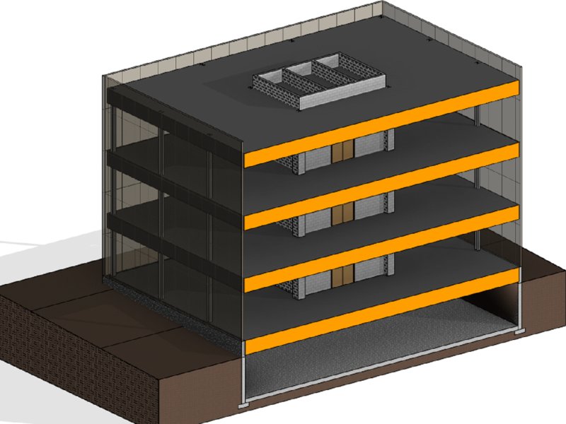
Figure 13.1 You can use a single floor type to show the entire floor/ceiling sandwich in early design.
During intermediate phases of design, you can model ceilings so the floor types can include only the floor and a structural layer, as shown in Figure 13.2. Columns may be created, but more precise horizontal structural framing may not be modeled yet. The layer within the floor type represents an assumption of the maximum depth of structural framing.
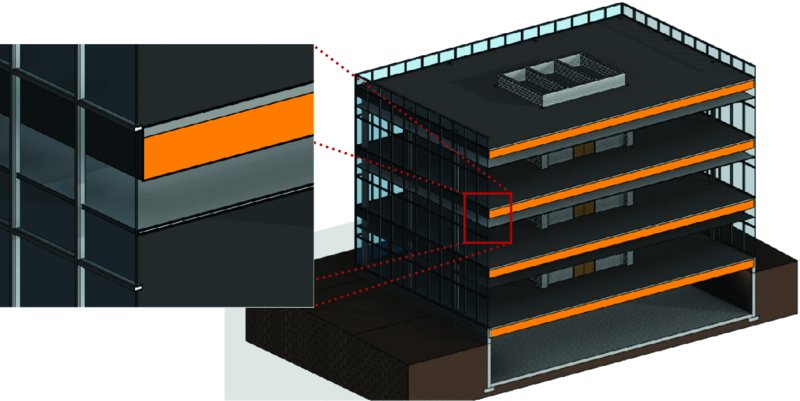
Figure 13.2 This floor assembly includes an assumption for the depth of structural framing.
In later phases of documentation approaching and including construction, floors should be modeled as close to actual conditions as possible. You should accommodate detailed finish conditions for floors as well as coordination with a resolved structural system. Accurate modeling of these conditions will help support consistent quantity takeoffs and interference detection. Figure 13.3 illustrates an example of a more accurate floor slab.
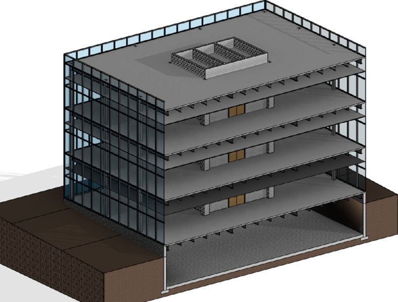
Figure 13.3 Floor assemblies for construction should be accurate and separate from structural framing.
These floor assembly types are offered as suggestions for the sake of increased productivity. As such, they should be used with care, especially when performing quantity takeoffs for estimating. For example, the area of a floor will be the only accurate value to be extracted from a floor sandwich model in early design, not a volumetric material takeoff. For more information on the use of models by other disciplines, we recommend referring to the AIA document G202-2013 Project BIM Protocol Form, which lists authorized uses of a model at various levels of development. You can learn more about AIA contract documents at www.aia.org.
With a basic understanding of floors as elements of the building, let’s look at some properties of floors that allow expanded uses in the project model. These properties and floor types can help expand your use of floor systems to create better documentation.
Creating a Structural Floor
The structural floor is similar to a traditional floor but has structural functionality, such as the ability to indicate span direction and to contain structural profiles. For example, you can specify a composite metal deck profile, which will display in sections and details generated within your project. You can create a structural floor by selecting the floor element and clicking the instance property called Structural (Figure 13.4, fifth item from the top). Because Structural is an instance property, any floor type can become a structural floor.
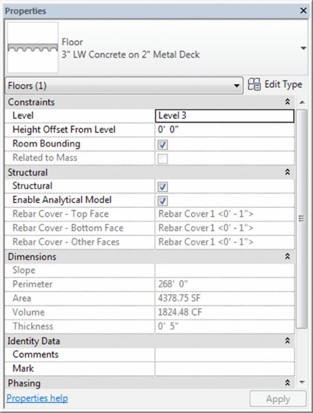
Figure 13.4 Structural parameter in a floor’s instance properties
After you select the Structural parameter check box for a floor, you can edit its type properties to add a structural decking layer. Let’s create a new structural floor so you can explore how this is done:
- Open the file
c13-Floors-Start.rvtorc13-Floors-Start-Metric.rvtfrom the book’s web page (www.sybex.com/go/masteringrevitarch2016), and activate the Level 3 floor plan. - Go to the Architecture tab in the ribbon, and from the Build panel, select Floor ➢ Floor: Structural.
- In the Draw panel of the contextual tab in the ribbon, make sure your options are set to Boundary Line with the Pick Walls tool, as shown in Figure 13.5.
-
In the Options bar, specify an offset of 0′-3″ (75 mm).
This setting will place the floor boundary just within the inner face of the curtain wall mullions because the location line of the curtain wall is at the center of the mullions that are 5″ (125 mm) deep.
-
Begin picking the exterior curtain walls by selecting one of the north-south–oriented walls first.
The first wall that you pick will determine the span direction of the structural floor. You can change this at any time by picking the Span Direction tool from the Draw panel and then selecting one of the boundary lines in the floor sketch.
-
Pick the remaining exterior walls to complete the floor boundary.
 After you finish defining the boundary lines of the floor, you will create a new floor type. If the Properties palette isn’t open, press Ctrl+1 on the keyboard, type PP, or click the Properties icon in the ribbon.
 - Click Edit Type in the Properties palette. Select Generic - 12″ or Generic - 300 mm as the active type and click Duplicate. Name the new type Structural Slab.
- In the Edit Type dialog box, click the Edit button in the Structure row to open the Edit Assembly dialog box.
- In the Edit Assembly dialog box, find the layer of the assembly that represents the generic floor you duplicated. This should be row 2. Change the material of this layer to Concrete – Cast-In-Place Concrete and change the thickness to 0′-6″ (150 mm).
-
Select row 3 and click the Insert button. There should now be four layers. Select the new row 3 and set its function to Structural Deck [1].
The new Structural Deck properties appear below the layers, as shown in Figure 13.6.
-
The value for Deck Profile should default to Form Deck_Non-Composite: 2′ × 6″ or M_Form Deck_Non-Composite: 50 × 150 mm, but this depends on whether you have a structural deck profile loaded into your project.
If you don’t have a structural deck profile loaded, finish the floor, select the Insert tab of the ribbon, and click Load Family. In your default Autodesk content library, find the
Profilesfolder and open theMetal Decksubfolder. Pick an appropriate deck profile and click Open to load it. Select the Structural Slab floor and click Edit Type in the Properties palette to continue the exercise. -
Activate Wall Section 1 and you should see the completed slab at Level 3.
Notice that you do not see the details of the structural decking when Detail Level is set to Coarse.
If you activate the callout at Level 3 (Detail At Level 3), you will see the structural decking because the callout’s detail level is set to Medium. This difference is illustrated in Figure 13.7.
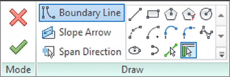
Figure 13.5 Use Pick Walls mode to draw boundary lines.
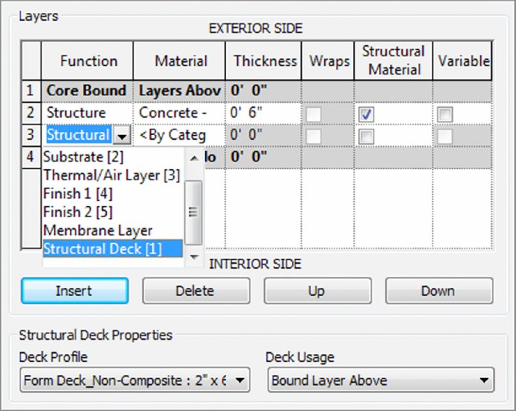
Figure 13.6 Setting a layer’s function to Structural Deck exposes additional options.
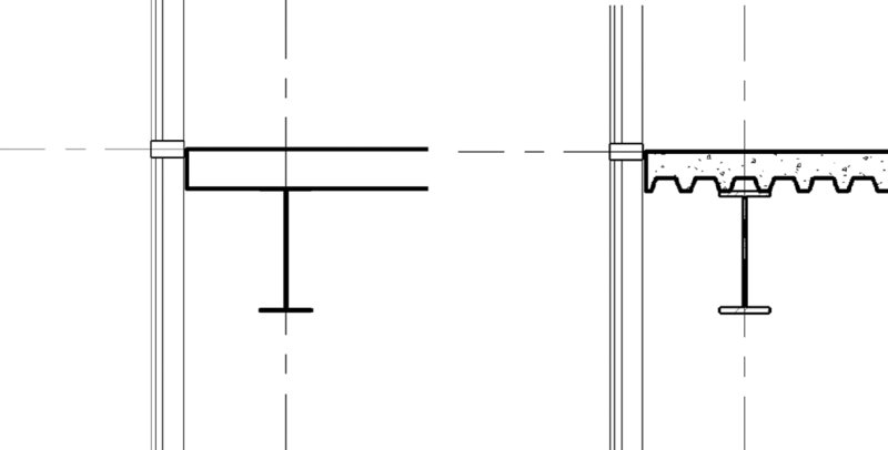
Figure 13.7 Structural floor as represented in Coarse detail level (left) and Medium detail level (right)
Modeling Floor by Face
This floor modeling method is used when you have generated an in-place mass or loaded a mass family. After you assign mass floors to a mass, you can use the floor-by-face method to assign and manage updates to floors, as shown in Figure 13.8. This type of face-based modeling is discussed in greater detail in Chapter 8, “Advanced Modeling and Massing.”
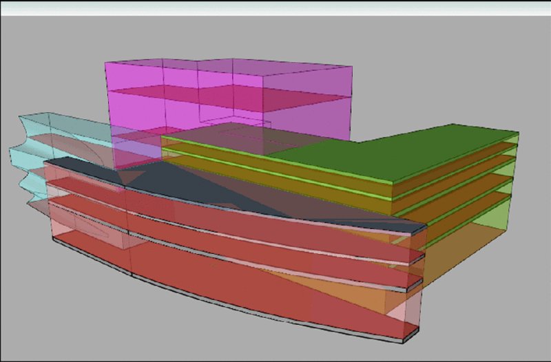
Figure 13.8 You can use the Floor By Face tool to manage slabs in more complex building designs.
Defining a Pad
A pad is technically not a floor but has properties similar to a floor. What differentiates a pad is its ability to cut into a toposurface or ground plane and define the lowest limits of a building’s basement or cellar. If desired, you can configure the pad to represent a slab on grade, as shown in Figure 13.9. The Pad tool can be found on the Model Site panel of the Massing & Site tab. If you don’t see this tab, you can access it by clicking the Application button and choosing Options ➢ User Interface.
For a more detailed exercise on creating building pads, refer to Chapter 3, “The Basics of the Toolbox.”
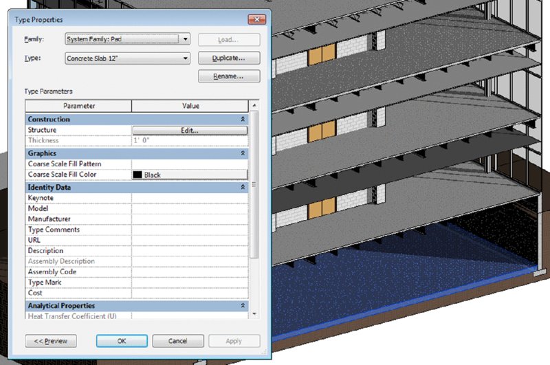
Figure 13.9 You can configure a pad as a slab on grade for a basement.
Sketching for Floors, Ceilings, and Roofs
Because floors, ceilings, and roofs are sketch-based objects, the method you use when creating the boundary lines is critical to the behavior of the element to those around it. The recommended method is to use the Pick Walls option, as shown earlier in Figure 13.5.
By selecting the walls to generate the sketch for the roof, you are creating a parametric relationship between the walls and the roof. If the design of your building changes and the wall position is modified, the roof will follow that change and adjust to the new wall position without any intervention from you (Figure 13.10).
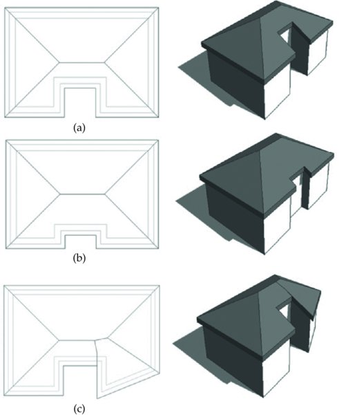
Figure 13.10 Using the Pick method: (a) original roof; (b) the entrance wall position has changed, and the roof updates automatically; (c) the angle of the wall to the right of the entrance has changed, and the roof changes to a new shape.
Also notice in Figure 13.10 that the illustrated roof was generated with overhangs beyond the exterior faces of the walls. You can specify an overhang or offset value for a floor, ceiling, or roof in the Options bar before picking walls to define the sketch.
If your building design is using curtain walls, be careful with the location lines of these walls. The location line of a curtain wall is defined relative to the offsets specified in the mullion and panel families that make up the curtain wall type. As discussed in Chapter 12, “Creating Walls and Curtain Walls,” you have many options when defining the relative location line of your curtain wall types. Refer to the exercise in the section “Creating a Structural Floor” earlier in this chapter for an example of picking curtain walls with an offset based on a centered location line.
Modeling Slab Edges
Slab Edge is a tool that allows you to create thickened portions of slabs typically located at the boundaries of floors. A slab edge type is composed of a profile family and a material assignment. It is important that the material assignment of the slab edge match that of the floor to which you will apply the slab edge in order to ensure proper joining of geometry. Let’s explore the application of a slab edge to a floor at grade:
- Open the file
c13-Design-Floor.rvtfrom the book’s web page and activate the 3D view named Floors Only. -
Click the Architecture tab in the ribbon and select Floor ➢ Slab Edge from the Build panel.
This tool is also available from the Structure tab.
- If necessary, orbit the 3D view so that you can see the bottom of the lowest floor slab. Pick all four bottom edges of the floor slab at the level named Ground.
-
Activate the view Section 1 and you will see the slab edge applied to and joined with the floor, as shown in Figure 13.11.
Remember that the material in the slab edge type must match the material in the floor type properties for the geometry to join properly.
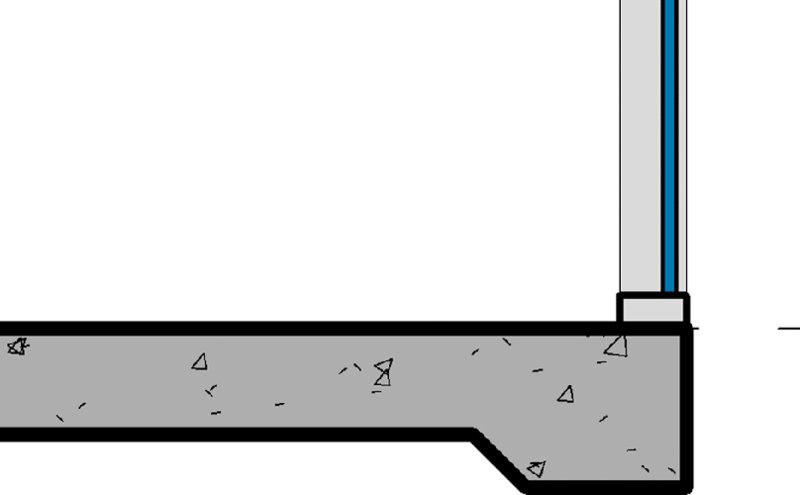
Figure 13.11 Thickened slab edge applied to the bottom of a floor
Creating a Custom Floor Edge
You can apply a great deal of flexibility to a floor assembly in early design. As we described previously, you can create a floor for early design phases that accommodates the floor, structure, plenum, and ceiling in a single floor type. You can also apply a customized edge to this type of assembly for more creative soffit conditions at exterior walls, as shown in Figure 13.12.
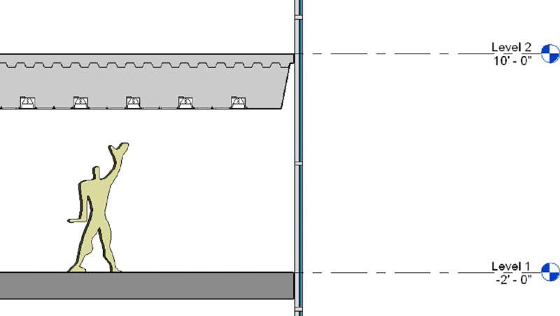
Figure 13.12 Customized edge applied to a floor assembly in early design
Let’s run through a short exercise so you can practice this skill:
- Open the file
c13-Design-Floor.rvtfrom the book’s web page or continue with the file from the previous exercise and activate the view Section 1. - Select the floor at Level 1 and open the Properties palette. Change the type to Design Floor Sandwich.
- Begin a new in-place component by going to the Architecture tab and selecting Component ➢ Model In-Place from the Build panel.
-
Set the Family Category to Floors and specify the name as Floor Edge-L1.
You are now in Family Editing mode and the ribbon will have different tabs and panels.
- Click the Create tab and select Void Forms ➢ Void Sweep from the Forms panel.
-
Click the Pick Path tool from the Sweep panel and choose all four top edges at the perimeter of the floor at Level 1.
You can activate the 3D view Floors Only to complete the picking of all four edges, as shown in Figure 13.13.
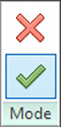
- Click the Finish Edit Mode icon in the Mode panel when all four edges of the floor have been picked.
-
Open the Properties palette if it isn’t already visible.
You might need to reactivate the Select Profile mode if the Properties palette lists only Family: Floors. To do this, click Select Profile in the contextual tab of the ribbon.
-
In the Profile parameter, select SD Sandwich Edge : Type 1 from the drop-down list, as shown in Figure 13.14.
The SD Sandwich Edge profile has been preloaded for the convenience of this exercise. If you would like to explore how this profile was created, expand the Families tree in the Project Browser and find Profiles ➢ SD Sandwich Edge. Right-click it and choose Edit from the context menu.
- You may need to adjust the orientation of the profile so that it faces in toward the floor, as shown in Figure 13.15. To do so, make sure the profile is selected, and click the Flip button in the Options bar or check the Profile Is Flipped option in the Properties palette.
- Switch to the Modify | Sweep tab in the ribbon and click the Finish Edit Mode icon from the Mode panel.
- Switch to the Modify | Void Sweep tab in the ribbon and select Cut ➢ Cut Geometry in the Geometry panel. Pick the void sweep and then the floor at Level 1.
-
Click Finish Model in the In-Place Editor panel at the right end of the ribbon.
Activate the Section 1 view, and you should see that the floor sandwich assembly at Level 1 has been customized in a similar way to the floor at Level 2 (Figure 13.16). You can experiment with adding embellishing detail components as shown in the section.
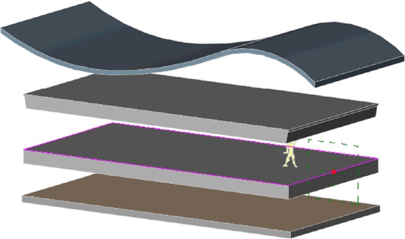
Figure 13.13 Pick edges of the void sweep in a 3D view.
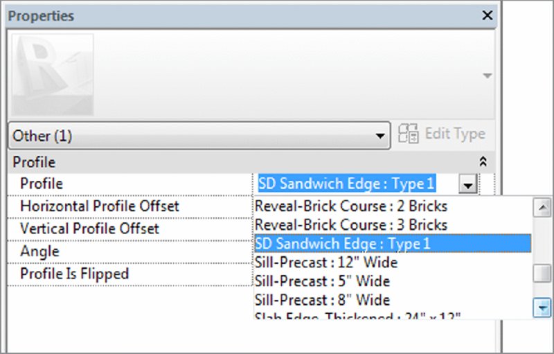
Figure 13.14 Select a loaded profile family for the void sweep.

Figure 13.15 Make sure the sweep profile is facing toward the floor.
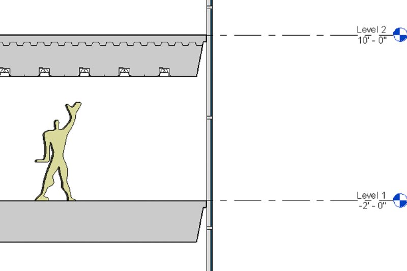
Figure 13.16 The edge of the floor sandwich assembly for Level 1 has been customized.
Modeling Floor Finishes
You can apply floor finishes in a variety of ways. Most methods are based on the thickness of the finish material. For example, a thin finish such as carpet might be applied with the Split Face and Paint tools, whereas a thicker finish such as mortar-set stone tile might be a separate floor type.
Using a Split Face for Thin Finishes
One of the easiest ways to divide a floor surface for thin finishes is to use the Split Face and Paint tools. This method will require a floor to be modeled and an appropriate material defined with at least a surface pattern. You can schedule finishes applied with the Paint tool only through Material Takeoff schedules. Let’s explore this method with a quick exercise:
-
Open the file
c13-Design-Floor.rvtfrom the book’s web page or continue with the file from the previous exercise and activate the Level 1 floor plan.You will see an area of the floor that is bounded by a wall and two reference planes.
- Click the Modify tab in the ribbon, activate the Split Face tool from the upper-right corner of the Geometry panel, and pick the floor in the Level 1 floor plan.
-
Draw a rectangle in front of the three interior walls, as shown in Figure 13.17.
You can constrain—or lock—the sketch lines to the interior walls, reference planes, and floor edge. You may do so in this exercise, but use constraints sparingly in larger projects to avoid slower model performance and updating calculation time.
Also notice that you generated a complete rectangular sketch instead of only three bounding lines. You do not need to draw the boundary line at the edge of the floor; however, if you don’t include that line and the floor shape is modified in the future, the split face may be deleted because it is no longer a closed-loop sketch.
- Click the Finish Edit Mode icon in the Mode panel.
- Return to the Modify tab in the ribbon and activate the Paint tool in the Geometry panel, just below the Split Face tool.
-
In the Material Browser, type carpet in the filter search at the top.
This will minimize your choices, allowing you to select Carpet Tile from the filtered list (Figure 13.18).
-
In the Level 1 floor plan, click near the edge of the split face you created earlier to assign the material.
The result should look like Figure 13.19.
- Click the Done button in the Material Browser to exit the Paint command.
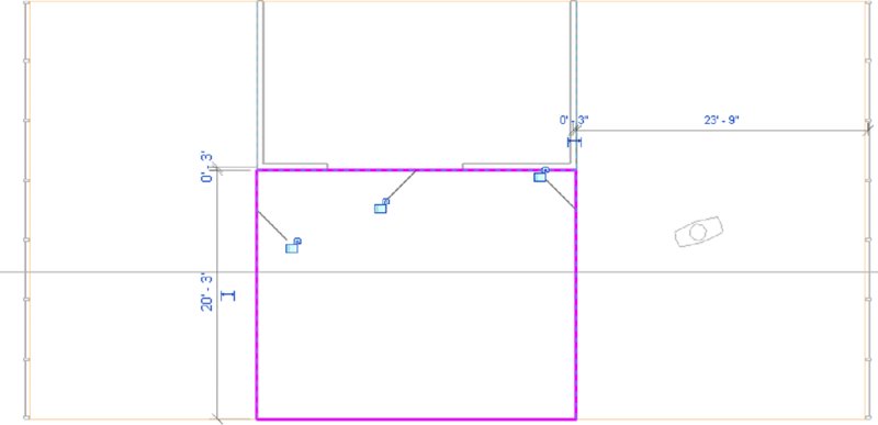
Figure 13.17 Sketch a rectangular boundary with the Split Face tool.
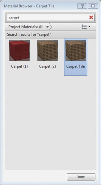
Figure 13.18 Choosing the Carpet Tile material
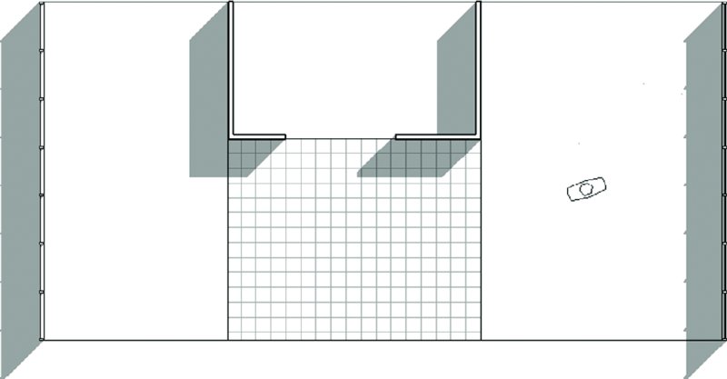
Figure 13.19 Completed application of carpet tile material to a split face on a floor
Modeling Thick Finishes
Thicker finish materials such as tile, stone pavers, or terrazzo can be applied as unique floor types and modeled where required. For large areas of finish such as a public atrium or airport terminal, you can assign these materials within the layers of a floor assembly. When you need to add smaller areas of thick floor finishes, you may encounter one of two scenarios: with a depressed floor and without.
In areas such as bathrooms, a thick-set tile floor may require the structural slab to be depressed in order to accommodate the thickness of the finish material. In Figure 13.20, the main floor object has been cut with an opening at the inside face of the walls. Another floor has been modeled with a negative offset value to accommodate the thickness of the tile material, and the tile has been placed as a unique floor element.
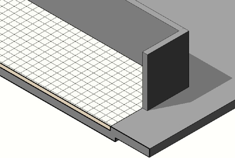
Figure 13.20 The thick tile finish and depressed slab are modeled as separate elements.
If you don’t need a finish but just a slab depression, you can create it with an in-place void extrusion. Select the Architecture tab in the ribbon and click Component ➢ Model In-Place. Choose the Floors category and create a void extrusion where you need a slab depression. Remember to use the Cut Geometry tool to cut the void from the floor before finishing the family. As an alternative, you can create a floor-based generic family that contains a parametric void extrusion. You can download the file c13-Slab-Depression.rfa as an example of this type of family from the book’s web page.
Finally, if the structural requirements allow a thick finish to be applied to a floor without dropping the structural slab, a finish floor element can be modeled directly in place within the structural slab. As shown in Figure 13.21, the tile floor has been graphically embedded in the structural floor using the Join Geometry tool. To do this, click the Modify tab in the ribbon and click Join Geometry. Be sure to pick the finish floor before the structural floor or you will get an error.
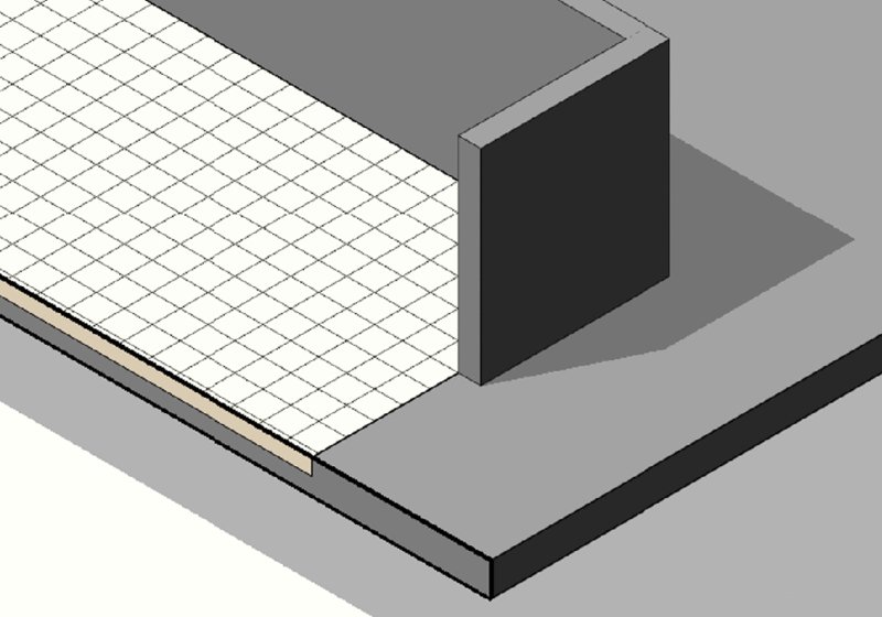
Figure 13.21 The thick tile finish floor has been joined with the structural floor.
Creating Ceilings
Ceilings are system families composed of sketch-based elements that also serve as hosts for components such as light fixtures. Like other host elements such as floors and roofs, if a ceiling is deleted, hosted elements on that ceiling are also deleted.
Ceilings are classified as either Basic Ceiling or Compound Ceiling. The Basic Ceiling family does not have a layered assembly and is represented in a section as a single line; however, it does have a material parameter that can display surface patterns in reflected ceiling plans and 3D views. The Compound Ceiling family allows you to define a layered assembly of materials that are visible when displayed in a section view. As with floors, you can change ceiling types by selecting a ceiling in your project and choosing another type from the Type Selector in the Properties palette or with the Match Type Properties tool.
Both the Basic Ceiling and Compound Ceiling types can serve as a host to hosted family components. Ceilings also serve as bounding elements for the volumetric calculation of rooms. This is critical when using environmental analysis programs. For more information about analysis for sustainable design, see Chapter 9, “Conceptual Design and Design Analysis.”
You can create a ceiling in one of two ways: automatically or by sketching a boundary. When you select the ceiling tool from the Architecture tab of the ribbon, you can switch between the Automatic Ceiling and Sketch Ceiling modes at the right end of the ribbon.
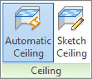
In Automatic Ceiling mode, the software will try to determine the boundaries of a ceiling sketch when you place the cursor inside an enclosed space. If an enclosed space cannot be determined, the cursor will still indicate a circle/slash and you must switch to Sketch Ceiling mode. In this mode, you can use the Pick Walls method as discussed earlier in this chapter to create intelligent relationships with the bounding walls of the ceiling.
Ceilings are best modeled in ceiling plans even though they can be created in a floor plan. When you place a ceiling, its elevation will be based on the level of the current plan with an offset from that level. With the Properties palette open, the Height Offset From Level value can be modified as you create ceilings.
Understanding Roof Modeling Methods
In today’s construction environment, roofs come in a great number of shapes and sizes. They can be as simple as a pitched shed roof or can involve complex double-curved surfaces or intersecting vaults. Once you understand the fundamental concepts, tools, and logic pertaining to roofs, you will be able to design almost any roof shape.
Roofs are similar to floors and ceilings because they are sketch-based elements and can be defined in generic types or with specific material assemblies. You can also change a roof element from one type to another in the same manner as you can a floor or ceiling. A fundamental difference between floors and roofs is that a roof’s thickness is generated above its referencing level, not below. You can also easily create slopes in roofs by defining slopes in the roof’s sketch lines.
In general, roofs can be constructed in four different ways:
- By footprint
- By extrusion
- By face
- Modeled in place
Before we start into how to create the roofs themselves, let’s take a look at some of the important instance properties for the roof family. These properties will need to be set properly to get the desired roof type, and they are all are found in the Properties palette (Figure 13.22).
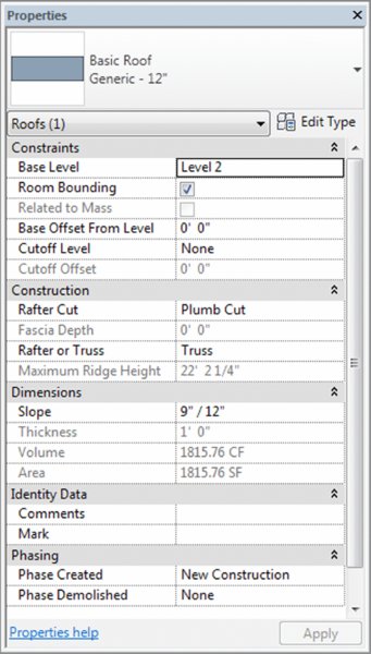
Figure 13.22 Roof instance properties
Base Level As in other Revit elements, this is the level at which the roof is placed. The roof moves with this level if the level changes height.
Room Bounding When this is checked, the roof geometry has an effect on calculating room area and volume.
Related To Mass This property is active only if a roof has been created with the roof-by-face method (Conceptual Mass tools).
Base Offset From Level This option lowers or elevates the base of the roof relative to the base level.
Cutoff Level Many roof shapes require a combination of several roofs on top of each other—for this you need to cut off the top of a lower roof to accommodate the creation of the next roof in the sequence. Figure 13.23 shows an excellent example of this technique.
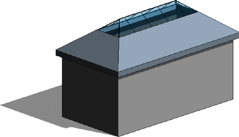
Figure 13.23 The cutoff level applied to the main roof, and a secondary roof built on top of the main roof using the cutoff level as a base
Cutoff Offset When the Cutoff tool is applied, the Cutoff Offset value also becomes active and allows you to set the cutoff distance from the level indicated in the Cutoff Level parameter.
Rafter Cut This defines the eave shape. You can select from Plumb Cut, Two Cut–Plumb, or Two Cut–Square. When either Two Cut–Plumb or Two Cut–Square is selected, the Fascia Depth parameter is activated, and you can set the value for the depth.
Rafter Or Truss With Rafter, the offset of the base is measured from the inside of the wall. If you choose Truss, the plate offset from the base is measured from the outside of the wall. Figure 13.24 illustrates the difference between the Rafter and Truss settings.
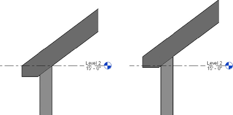
Figure 13.24 Rafter setting (left) and Truss setting (right) for roofs
The following sections provide a closer look at the different approaches to modeling roofs.
Constructing a Roof by Footprint
Use the roof-by-footprint method to create any standard roof that more or less follows the shape of the footprint of the building and is a simple combination of roof pitches (Figure 13.25).
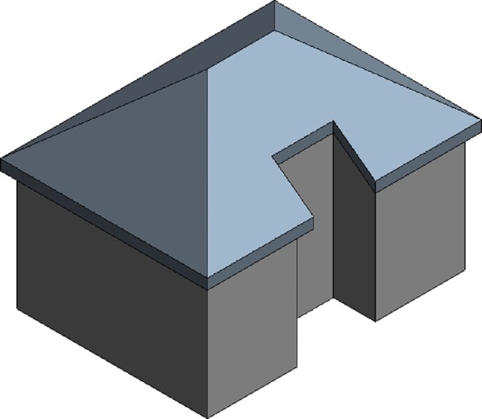
Figure 13.25 A simple roof created using the roof-by-footprint method
These roofs are based on a sketched shape that you define in plan view at the soffit level and that can be edited at any time during the development of a project from plan and axon 3D views. The shape can be drawn as a simple loop of lines, using the Line tool, or can be created using the Pick Walls method, which also should result in a closed loop of lines.
To guide you through the creation of a roof by footprint and explain some of the main principles and tools, here is a brief exercise demonstrating the steps:
-
In a new project using any default template, open a Level 1 plan view and create a building footprint similar to Figure 13.26.
Make sure the height of the walls is set to Unconnected: 20′-0″ (6000 mm).
- Activate the Level 2 plan; then select the Architecture tab in the ribbon and click Roof ➢ Roof By Footprint.
- From the Draw panel in the Modify | Create Roof Footprint tab, select the Pick Walls tool (this should be the default).
-
When you’ve chosen to create a roof by footprint, the Options bar displays the following settings (change the Overhang value to 1′-0″ (300 mm)).

To define whether you want a sloped or flat roof, use the Defines Slope check box in the Options bar. The Overhang parameter allows you to define the value of the roof overhang beyond the wall. When the Extend To Wall Core option is checked, the overhang is measured from the wall core. If the option is deselected, the overhang is measured from the exterior face of the wall.
-
After defining these settings, place the cursor over one of the walls (don’t click), and using the Tab key, select all connected walls.
Your display should look like Figure 13.27.
- Select the three walls within the alcove, open the Properties palette, and uncheck the Defines Roof Slope parameter, as shown in Figure 13.28.
- Click the Finish Edit Mode icon in the Mode panel of the ribbon. If you are prompted with the question, “Would you like to attach the highlighted walls to the roof?” click the Yes button. Activate a 3D view, and your roof should like the image in Figure 13.25 shown previously.
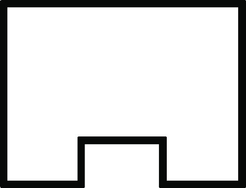
Figure 13.26 Sample building outline to be sketched on Level 1
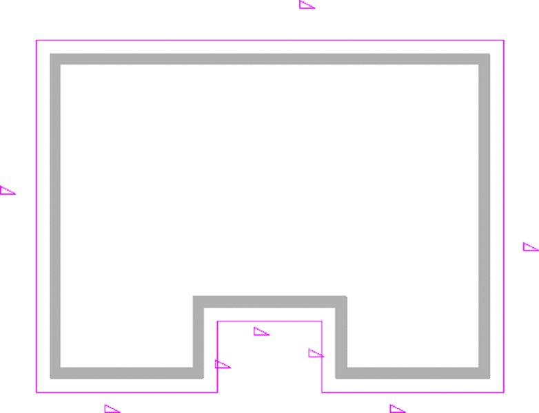
Figure 13.27 Roof sketch lines are automatically drawn after Tab+selecting the bounding walls, and they are offset from the walls by the value of the overhang as defined in the Options bar.
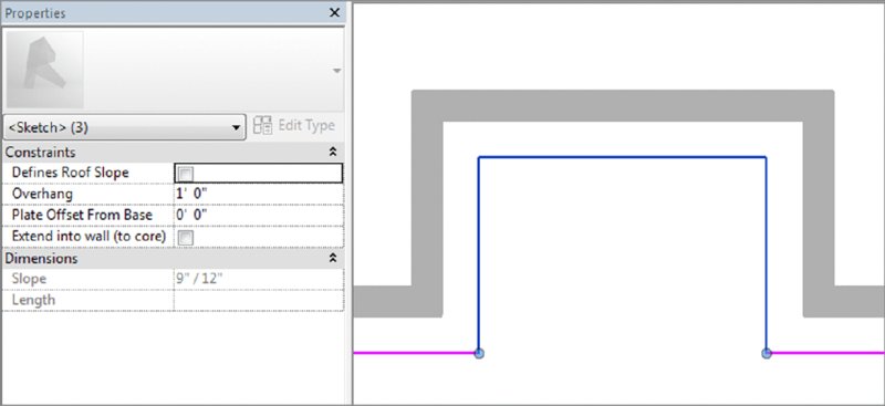
Figure 13.28 Uncheck the Defines Roof Slope parameter for two of the roof’s boundary lines.
If the shape of the roof doesn’t correspond to your expectations, you can select the roof and select Edit Footprint from the Mode panel in the Modify | Roofs tab to return to Sketch mode, where you can edit lines, sketch new lines, pick new walls, or modify the slope.
To change the slope definition or angle of individual portions of the roof while editing a roof’s footprint, select the sketch line of the roof portion for which you want to change the slope and toggle (check) the Defines Slope button in the Options bar, toggle the Defines Roof Slope parameter in the Properties palette, or right-click and choose Toggle Slope Defining. If you mistakenly made all roof sides with slope but wanted to make a flat roof, you can Tab+select all sketch lines that form the roof shape and clear the Defines Slope box in the Options bar. You can dynamically change the roof slope by selecting the roof and then selecting the blue grips (Figure 13.29) and dragging them either up or down to make the roof pitch steeper or shallower. This is a great way to make quick (although not precise) edits to the roof pitch.
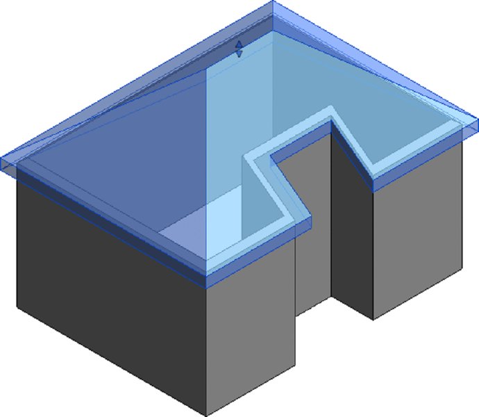
Figure 13.29 Select the roof and use the blue grips to dynamically change the roof slope.
Roof slope can be measured in two different ways: as an angle or as a percentage rise. You can find all slope-measuring options in the Manage tab by selecting Project Units in the Project Settings panel and then selecting Slope to open the Format dialog box (see Figure 13.30). If the current slope value is not in units you want to have (suppose it displays percentage but you want it to display an angle), change the slope units in the Format dialog box—you will not be able to do that while editing the roof slope. Setting it here means specifying the way you measure slopes for the entire project.
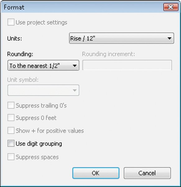
Figure 13.30 Format dialog box for slopes
Applying a Roof by Extrusion
The roof by extrusion method is best applied for roof shapes that are generated by extrusion of a profile, such as sawtooth roofs, barrel vaults, and waveform roofs. Like the roof-by-footprint method, it is based on a sketch; however, the sketch that defines the shape of the roof is drawn in elevation or section view (not in plan view) and is then extruded along the plan of the building (see Figure 13.31).
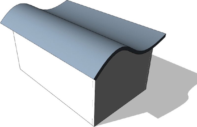
Figure 13.31 An extruded spline-shaped roof
Roofs by extrusion do not have an option to follow the building footprint, but that is often needed to accommodate the requirements of the design. To accomplish this, you can use the Vertical Opening tool to trim the edges of an extruded roof relative to the building outline.
Let’s briefly review the concept behind the Vertical Opening tool: You create a roof by extrusion by defining a profile in elevation or 3D that is then extruded above the building. The extrusion is usually based on a work plane that is not perpendicular to the building footprint, as shown in Figure 13.32. If the shape of the building is nonrectangular in footprint or the shape of the roof you want to create is not to be rectangular, this tool will let you carve geometry from the roof to match the footprint of the building or get any plan shape you need using a plan sketch.
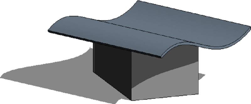
Figure 13.32 Extruded roof created at an angle to the building geometry
 With sketch-based design, any closed loop of lines creates a positive shape; every loop inside it is negative, the next one inside that negative one will be positive, and so on. In Figure 13.33, a roof by extrusion was drawn at an angle to the underlying walls, but the final roof shape should be limited to a small offset from the walls. To clip the roof to the shape of the building footprint, the Vertical Opening tool was used to draw, in plan view of the roof, a negative shape that will remove the portions of the roof that extend beyond the walls.
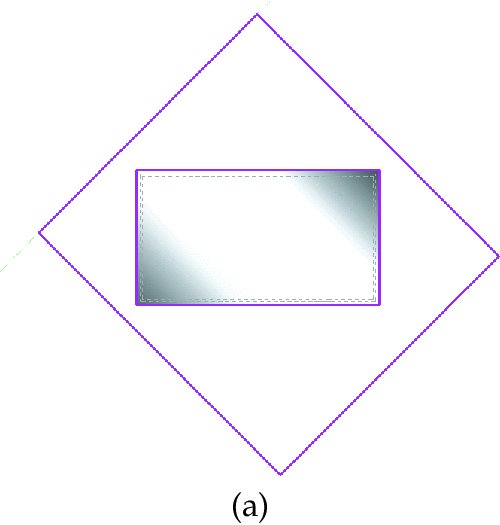
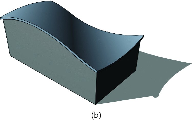
Figure 13.33 The Vertical Opening tool with two sketch loops trims the roof to the inner loop.
Roof In-place
The roof in-place technique accommodates roof shapes that cannot be achieved with either of the previously mentioned methods. It is the usual way to model historic roof shapes or challenging roof geometries such as those illustrated in Figure 13.34. The figure shows a barrel roof with a half dome (Extrusion + 1/2 Revolve), a dome roof (Revolve only or Revolve + Extrusion), and a traditional Russian onion dome (Revolve only).
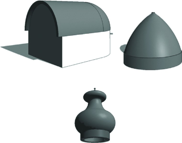
Figure 13.34 Examples of modeled in-place roofs
To create an in-place roof, select the Architecture tab in the ribbon and click Component ➢ Model In-Place from the Build panel. Select Roofs from the Family Category list and click OK. While you remain in the In-Place Family editing mode, you can create any roof shape using solids and voids of extrusions, blends, revolves, sweeps, and swept blends (Figure 13.35). More advanced editing techniques are discussed later in this chapter, in the section “Using Advanced Shape Editing with Floors and Roofs.”
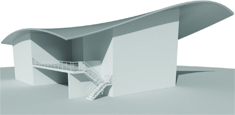
Figure 13.35 Organic-shaped roof created using the Swept Blend modeling technique
Creating a Roof by Face
The Roof By Face tool is to be used when you have created an in-place mass or loaded a mass family. These types of roofs are typically more integrated with the overall building geometry than the examples we’ve shown for in-place roofs. You can find more detailed information about using face-based methods in Chapter 8.
Creating a Sloped Glazing
In Chapter 12, you learned that a curtain wall is just another wall type made out of panels and mullions organized in a grid system. Similarly, sloped glazing is just another type of a roof that has glass as material and mullions for divisions. Using sloped glazing, you can make roof lights and shed lights and use them to design simple framing structures.
To create sloped glazing, make a simple pitched roof, select it, and use the Properties palette to change the type to Sloped Glazing. Once you have done that, activate a 3D view and use the Curtain Grid tool from the Build panel of the Architecture tab in the ribbon to start applying horizontal or vertical grids that define the panel sizes; then you can apply mullions using the Mullion tool in the Build panel. Figure 13.36 illustrates an example of a standard gable roof that has been converted to sloped glazing. Refer to Chapter 12 for more information on using the Curtain Grid and Mullion tools.
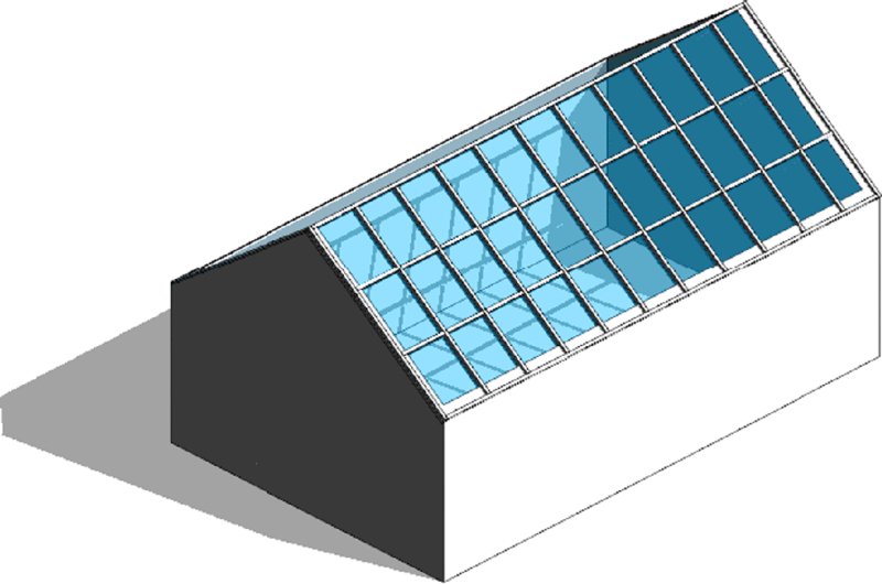
Figure 13.36 Sloped glazing is created by switching a standard roof to the Sloped Glazing type and assigning grids and mullions.
Using Slope Arrows
If your design calls for a sloped roof with an unusual footprint that does not easily lend itself to using the Defines Slope property of boundary lines, slope arrows can be added within the sketch of the roof. First, create the sketch lines to define the shape of a roof, but don’t check Defines Slope in the Options bar. Instead, choose the Slope Arrow tool from the Draw panel. Draw the slope arrow in the direction you want your roof to pitch. Select the arrow, and in the Properties palette, you can set any of the parameters, as shown in Figure 13.37. The Specify parameter can be set to either Height At Tail or Slope. If you choose Height At Tail, be sure to specify the Height Offset At Head parameter as the end result of the desired slope.
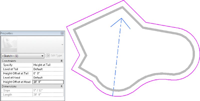
Figure 13.37 Defining the properties of a slope arrow added to an irregular footprint roof sketch
Using Additional Roof Tools
The following three roof tools (Figure 13.38) can be found under the Roof flyout:
- Roof : Soffit
- Roof : Fascia
- Roof : Gutter
Each of these tools behaves in a similar fashion—it uses a profile that is swept along the edge of the roof.
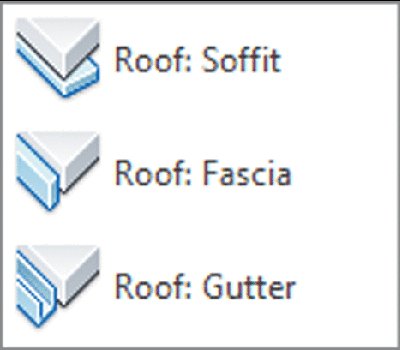
Figure 13.38 Edge condition roof tools
The difference between these tools is fairly simple. The Soffit tool will sweep a profile to the underside of a roof overhang parallel to the ground. The Fascia tool will sweep a profile along the vertical face of the roof edge, and the Gutter tool will sweep a profile along one of the edges of the roof. Try these tools on the roofs you’ve created in this chapter to better understand how they react to roof conditions. You can see how the Gutter tool looks using the default profile in Figure 13.39.
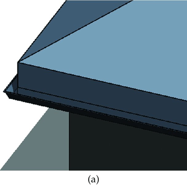
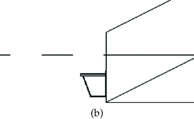
Figure 13.39 The Gutter tool
Don’t feel you’re limited to residential uses with these tools—as an example, the Gutter tool can be used to create a break metal cap for a flat roof parapet. Do be careful when you are picking an edge to apply the Gutter tool. The best approach is to pick in-plan views because the Gutter tool will default to the lower of the two edges so your gutters will be all placed at a consistent level.
Using Advanced Shape Editing with Floors and Roofs
No flat roof is ever really flat! Fortunately there are tools that allow you to model tapered insulation over a flat roof and similar conditions to give the roof a small pitch. These powerful tools are modifiers that are applicable to roofs and floors and will allow you to model concrete slabs with multiple slopes for sidewalks or roof assemblies with tapered insulation (see Figure 13.40).
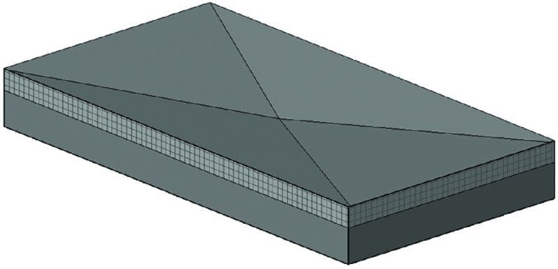
Figure 13.40 Roof with sloped drainage layer
The set of tools available for editing floor and roof shapes appears in the ribbon when you select a flat floor or roof. If the Reset Shape command is inactive, that means the selected element has not been modified with the shape editing tools.
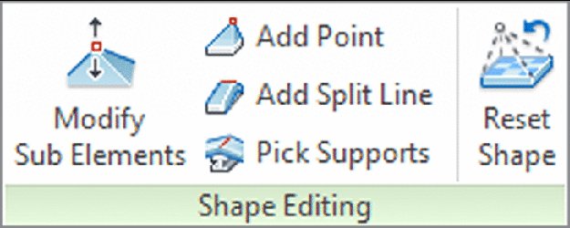
Let’s look at what each tool does:
Modify Sub Elements This tool allows you to directly edit element geometry by selecting and modifying points and edges. If you don’t create any additional points or split lines before activating this tool, the object’s outer edges and corners will be available for editing.
Add Point This tool allows you to add points on the top face of a roof or floor. Points can be added on edges or surfaces and can be modified after placement using the Modify Sub Elements tool.
Add Split Line This tool allows you to sketch directly on the top face of the element, which adds vertices so that hips and valleys can be created when the elevations of the lines are modified using the Modify Sub Elements tool.
Pick Supports This tool allows you to pick linear beams and walls in order to create new split edges and set the slope and/or elevation of the floor or roof automatically.
Once a floor or roof has been modified using any of these tools, the Reset Shape button will become active. You can use this tool to remove all modifications you applied to the selected floor or roof.
Creating a Roof with a Sloped Topping
Let’s work through an exercise that shows you how to make a roof with a sloped topping like the one shown in Figure 13.41 (shown in plan view).
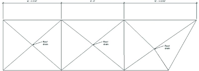
Figure 13.41 A roof plan showing a roof divided in segments, with drainage points
Follow these steps:
- Open
c13-Roof-Edit.rvtorc13-Roof-Edit-Metric.rvtfrom the book’s web page. Activate the Roof floor plan. - Select the roof that has already been prepared for you.
- Activate the Add Split Line tool (the color of the rest of the model grays out while the roof lines are dashed green).
-
Sketch two ridge lines to divide the roof into three areas that will be independently drained.
The ridge lines will be drawn in blue.
-
Using the same tool, draw diagonal lines within those areas to create the valleys.
Make sure you zoom in closely when drawing the diagonal lines, and be sure that you are snapping in the exact same dividing points. (If you notice that the split lines are not snapped to the correct points, select the Modify Sub Elements tool, pick the incorrect lines, delete them, and try again.)
You have split the roof surface into many regions, but they are still all at the same height and pitch. You should have a roof that looks like Figure 13.42.
Press the Esc key or click the Modify button to stop the editing mode.
- Switch to a 3D view.
- To add a slope, you need to edit the height of the drainage points or the heights of the edges and ridges created by the split lines. For this exercise, you will raise the elevation of the boundary edges and ridges. Activate the Modify Sub Elements tool and select an edge of the roof (dashed green line). New controls that allow you to edit the text will appear, and you can either move the arrows up and down or type in a value for the height. Type in 1′-0″ (300 mm).
- Repeat step 7 for all boundary edges and the two north-south split lines forming the ridges between the drainage areas.
- Make a section through the roof—if possible, somewhere through one of the drainage points. Open the section; change Detail Level to Fine to see all layers.
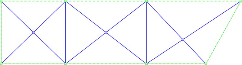
Figure 13.42 Using the Add Split Line tool, you can create ridges and valleys.
The entire roof structure is now sloped toward the drainage point.

Applying a Variable Thickness to a Roof Layer
What if you wanted the insulation to be tapered but not the structure? For that, the layers of the roofs can now have variable thickness. Let’s see how to apply a variable thickness to a layer of the roof assembly.
- Continuing with the
c13-Roof-Edit.rvtorc13-Roof-Edit-Metric.rvtfile from the previous exercise, select the roof, and in the Properties palette select Edit Type to view the roof’s type properties. Click Edit in the Structure row to edit the layers of the roof assembly. - Activate the preview. You will notice that in the roof-structure preview, you do not see any slopes. That is correct and will not change. This preview is just a schematic preview of the structure and does not show the exact sloping. Look for the Variable column under Layers, as shown in Figure 13.43. This allows layers of the roof to vary in thickness when slopes are present. Check the Variable option for the insulation material.
-
Go back to the section view and observe the changes in the roof assembly.
As you can see, only the insulation is tapered, while the structure remains flat.

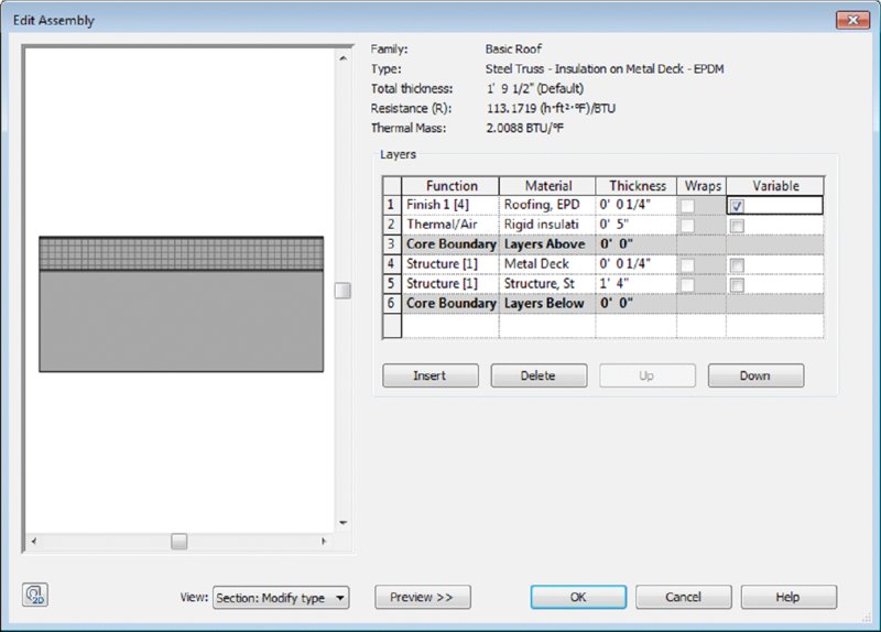
Figure 13.43 Specify variable layers of material in the Edit Assembly dialog box.
You will only be able to modify an adjustable layer of a floor or roof with a negative value to the next nonadjustable layer of the assembly. In the previous exercise, for example, if you modified the drainage points by more than –0′-5″ (–130 mm), an error would be generated, and the edits to the roof would be removed. You must think about the design requirements of your roof or floor assembly when planning how to model adjustable layers. An alternative approach to the previous exercise might have been to increase the thickness of the insulation layer in the roof assembly to that required at the high pitch points. The drainage points could then be lowered relative to the boundary edges and ridge lines.
The Bottom Line
Understand floor modeling methods. Floors make up one of the most fundamental, sketch-based system families used in a Revit model. You can customize them to accommodate a variety of assumptions at various stages of design.
Master It How can you create a structural floor with integrated metal decking?
Model various floor finishes. Thick and thin floor finishes can be created to support tagging, scheduling, and quantity takeoffs.
Master It How would you represent a thin finish material in your project such as carpet?
Create ceilings. Ceilings are sketch-based system families that can host objects such as light fixtures and HVAC diffusers.
Master It What’s the best way to model a ceiling within a space?
Understand roof modeling methods. Roofs can be modeled as simple single-pitch shed roofs or complex extrusions of sinuous curves.
Master It What is the best way to create a single vault roof?
Work with advanced shape editing for floors and roofs. A small but powerful toolset is available for extended editing of floor and roof objects. These tools allow you to create warped floor slabs and tapered layers of roof assemblies.
Master It How do you create a drainage point in a flat roof slab?