
Chapter 16
Detailing Your Design
As you’ve seen so far, you can show information in Autodesk® Revit® Architecture software in a variety of ways, including 3D views, plans, sections, and elevations. In each of these cases, the geometry is typically modeled based on design intent, meaning that your goal isn’t to model everything but to model enough to capture the overall scope of the proposed building. To this end, it becomes necessary to embellish the model in specific views with more detailed information. These take the shape of 2D detail elements that you will use to augment views and add extra information.
In this chapter, you’ll learn to:
- Create details
- Add detail components to families
- Learn efficient detailing
- Reuse details from other files
Creating Details
If you are accustomed to using 2D CAD software applications to create drawings, you should first be aware of how the detailing process in Revit differs from CAD drafting. In Autodesk® AutoCAD® software, for example, you would create a new DWG file and then add lines, arcs, circles, hatch patterns, text, and dimensions to develop a detail. You might use blocks to combine repeatable elements to increase efficiency and maintain consistency. In Revit, you will create additional views within the project file, to which you might add 2D embellishment along with annotation and dimensions. Details can incorporate parts of the 3D model or can be empty views exclusive to 2D elements.
View Types for Detailing
Before we discuss the process of detailing, let’s review the fundamental views in which you can create details: detail views and drafting views.
Detail Views Detail views are essentially subsets of the views we’ve discussed previously in this book such as plans, elevations, and sections. When you create a new section or callout, you can select Detail View from the Type Selector. The model is still displayed in a detail view, but you can set the Display Model view property to Do Not Display if necessary.
Because you can use detailing tools in any view, we will refer to any view that displays the model as a detail view throughout the remainder of this chapter.
Refer to Chapter 2, “Applying the Principles of the User Interface and Project Organization,” for more information about the difference between callouts and detail views.
Drafting Views Drafting views do not display model content. Instead, they are simply a blank canvas within which you can create details using only 2D elements such as lines, arcs, circles, or 2D families. Drafting views can be associated with sections or callouts, but those view references will display a reference label such as SIM (similar) or TYP (typical). You can customize the Reference Label value in the type properties of each view.

Download and open the file c16-Sample-Building.rvt or c16-Sample-Metric.rvt from this book’s web page (www.sybex.com/go/masteringrevitarch2016).
From the Project Browser, activate the view Section 2, and you will see an overall section of the building. We will create a more detailed section callout of the exterior wall at the right side of the view. Let’s walk through the steps to generate this view:
- Switch to the View tab in the ribbon, locate the Create panel, and then click Callout ➢ Rectangle.
- In the Type Selector, change the view type to Wall Section.
- Sketch a rectangular region around the exterior wall at the right side of the building.
- When you finish sketching the new callout, it should look like the section view shown in Figure 16.1. Double-click the callout head to activate the new view.
-
In the Properties palette, change the View Name to Wall Section North, set the Detail Level to Medium, and change the Scale to 1/2″=1′-0″ (1:25).
You have taken the first step toward creating the path from the overall down to the specific. From the plan and an overall section, you have created a wall section. Before we drill down even further, let’s break the view down in order to isolate only the transition conditions at floors and roof.
- Select the crop region in the wall section view and you will see a number of view break icons. Click one of the Horizontal View Break icons along either vertical edge of the crop region.
- You now have two crop subregions, but you will need to create one more. Select the crop region again, and then click and drag the grip at the bottom of the upper subregion to stretch it downward. Do not drag it too close to the lower subregion because it will rejoin the subregions back into the original crop boundary.
- Use the grips at the top edge and bottom edge of the three subregions to show the intersection conditions with the Level 1, Level 2, and Roof.
-
Select the crop region once again, and you will see vertical double arrows at the middle of each subregion. Use these arrows to move the subregions closer together.
The final result of this exercise should look like the image in Figure 16.2.

Figure 16.1 Wall section callout added to building section view

Figure 16.2 Wall section view broken into subregions
Working with the Detailing Process
Now that you have completed the setup of a detail view, we will discuss three different methodologies with which you can approach the detailing process: stand-alone detailing, hybrid detailing, and model detailing. These are terms we invented to help you understand and plan your detailing efforts as your skills improve in the Revit environment.
Stand-alone Detailing (Beginner) If you are relatively new to the Revit environment, you might choose to develop your details without any part of the 3D model serving the detail. In this scenario, you can use either detail views or drafting views; however, you may tend to use more of the latter. If you use detail views, the Display Model view property (in the Property Palette with the view selected) will most often be set to Do Not Display. This setting allows you to see the model components in a regular line weight, half tone, or not at all in a detail view.
With a stand-alone detailing approach, you forfeit some ability to ensure your details accurately reflect the modeled condition. In a detail view, you may temporarily return the Display Model view property to Normal or Halftone, but you may be able to draft more comfortably using the blank canvas of an empty view.
Hybrid Detailing (Intermediate) As you become more experienced with detailing in Revit, you may start to use a more balanced number of detail views and drafting views. With a hybrid approach you will maintain the model in any detail views and you will add detail components to embellish the 3D model. This approach tends to yield a more accurate representation of the intended design, but it will require more time and care to maintain as the model evolves throughout the design process.
In Figure 16.3, you can see a detail view in which the Display Model view property has been set to Halftone. This illustrates the difference between what is modeled and what is a detail component.

Figure 16.3 Example of a detail view with embellished drafting
Model Detailing (Advanced) The most complex approach to detailing can also be the most efficient—once you become familiar with creating families and customizing your project templates. The approach we refer to as model detailing still involves the use of some detail components; however, they are embedded into model elements where applicable. For example, in a wood-framed structure, detail elements such as sill plates, studs, joists, or anchors can be embedded in wall type definitions. The details will display automatically when the walls are displayed in a section detail view.
With any of these three methods we’ve described, there is a range in which you can use the model to help generate your details. You should plan your approach before you begin detailing in your project. As always, the more time you spend preparing your template content in the beginning, the less time you will need to develop your details later in the project.
Detailing Tools
Even when you’re creating details, Revit has a variety of parametric tools to allow you to leverage working in a BIM environment. You can use these tools to create strictly 2D geometry or to augment details you are trying to create from 3D plans, sections, or callouts. To become truly efficient at using Revit to create the drawings necessary to both design and document your project, it’s important to become acquainted with these tools—you will find yourself using them over and over again throughout your process.
All of these tools are located on the Detail panel of the Annotate tab. This small but very potent toolbox is what you will need to familiarize yourself with in order to create a majority of the 2D linework and components that will become the details in your project. To better demonstrate how these tools are used, let’s step through them to explain each one’s purpose. Note that some of the tools may not be available depending on the active view. For best results, make sure you have a plan or detail view active before continuing.
 Using the Detail Line Tool
The Detail Line tool is the first tool located on the Detail panel of the Annotate tab. This tool is the closest thing you’ll find to CAD drafting because it allows you to create view-specific linework using different line styles and it provides tools for drawing and manipulating different line shapes.
Detail lines are view specific—they appear only in the view in which they’re drawn. They also have an arrangement to their placement, meaning that you can layer them underneath or on top of other objects. This is especially important when you begin using a combination of regions, detail lines, and model content to create your details.
Using the Detail Line tool is fairly easy. Selecting the tool will change your ribbon tab to look like Figure 16.4. This new tab will have several panels that allow you to add and manipulate linework.

Figure 16.4 The Detail Line toolset
There are three major panels on this new tab: Line Style, Draw, and Modify. Because of their use sequence (selecting the line type, creating the shape, and modifying the line), we’ll talk about them in order from right to left.
Line Style This panel includes a drop-down menu that allows you to choose a line style in which to produce the linework in this view. The drop-down menu has all the default Revit line styles as well as any custom ones you might have made for your project or to accommodate office or client standards. The active line will be the one displayed in the drop-down window before it’s expanded.
New line styles can be added at any time in the project, and many offices find it necessary to add custom line styles beyond the thin, medium, and wide ones available in Revit out of the box. To add more styles or to just see the complete list, choose Additional Settings from the Manage tab and select Line Styles. For more information about creating your own custom line styles, refer to Chapter 4, “Configuring Templates and Standards.”
Draw The Draw panel contains a number of geometry tools to draw within the active view. The tools allow you to create lines, boxes, circles, splines, ellipses, and arcs. The last tool in the bottom row is the Pick tool. This tool allows you to select a line previously drawn or portion of a model element (say an edge) and add linework on top of the existing shape.
Modify The Modify panel has several tools that you can use to modify any of the linework already placed within the view. The larger tools, from left to right, are Align, Offset, Mirror (axis), Mirror (line), Move, Copy, Rotate, and Trim.
 Using the Linework Tool
Although not part of the Annotate tab, the Linework tool helps you make your detail composition more legible. Default settings for object styles and line weights will manage most of a view’s composition automatically, but you sometimes need to adjust a line or two to clarify a detail. The Linework tool allows you to modify the edges of model elements in a view-specific context. Note that this tool is not available in a drafting view because it works only on model elements.
 To use the Linework tool, switch to the Modify tab in the ribbon, locate the View panel, and click Linework. This will add the familiar Line Style selector panel at the end of the ribbon. Simply choose the line style you want to assign, and then select an edge of a model element. The edges you pick can be almost anything: cut lines of walls, families, edges of floor slabs, and so on. Selecting the edge of an element will change the default line style to the style you have chosen. To return an edge to its original line style, use the Linework tool again, but select <By Category> from the Line Style drop-down list.
You can also choose to remove lines using this tool. By selecting the <Invisible Lines> line type, you can make some edges disappear. Use this method instead of covering unwanted lines with masking regions.
Another great use of the Linework tool is to indicate the edges of overhead ceilings or floors in a floor plan view. To accomplish this task, set the Underlay property of the active view to the level where the ceiling, floor, or roof is associated. If necessary, set the Underlay Orientation to Reflected Ceiling Plan. Start the Linework tool, select an overhead line style, and then pick any edges you’d like to see in the floor plan view. When you’re finished, set the Underlay property back to None, and not only will the lines you created with the Linework tool remain, but they will update if the overhead model object is modified.
Let’s use the Linework tool to continue our exercise with the wall section detail by following these steps:
- Switch to the Modify tab in the ribbon, locate the View panel, and then click the Linework tool.
- From the Line Style drop-down menu in the contextual tab of the ribbon, choose Medium Lines.
- As indicated in Figure 16.5, click the inside face and the outside face of the exterior wall. Also click the edge of the wall below the window sill.

Figure 16.5 Use the Linework tool to modify the cut lines of the wall element in a detail.
Using Filled Regions and Masking Regions
The next tool on the Detail panel of the Annotate tab is the Region tool, which contains two individual commands: Filled Region and Masking Region. Regions are two-dimensional areas of any shape or size that you can fill with a pattern. This pattern (much like a hatch in AutoCAD software) will dynamically adjust based on changes to the region boundary. You can manipulate the draw order of regions in the same manner as detail lines. Regions also have a type property (Background) that can be set to Opaque (hiding the objects they are placed over) or Transparent (letting the elements below show through).
Filled regions allow you to choose from a variety of hatch patterns to fill the region. These are commonly used in details to illustrate materials like rigid insulation, concrete, or plywood. Masking regions, on the other hand, do not include a fill pattern. Masking regions are typically used to “hide” or mask certain content from a view that you don’t want shown or printed. As an example, there might be a particularly detailed way in which two walls join and their materials overlap. In some cases, it doesn’t make sense to model that condition, and it makes more sense to use detail lines to describe the condition. Here you would need to mask a portion of the view so you can essentially draw over it with new content.
When selecting the Region tool, you will be taken directly into Sketch mode, and you’ll have a series of tools similar to those for drawing detail lines. The Draw panel allows you to create any number of shapes with all the associated tools to move, copy, or offset the linework.
When creating either kind of region, it’s important to note that you cannot complete Sketch mode unless the boundaries you draw are in closed loops. You can create as many closed-loop boundaries as you want as long as they do not overlap and are all formed with closed loops (Figure 16.6). Notice in the figure that, in addition to the use of multiple closed loops, you can use any combination of line styles to draw the boundary of a region.

Figure 16.6 Multiple shapes within a single filled region
Another consideration for using regions is the linework that borders a region. When starting the Region tool, you’ll be able to choose the line style you want to use for the border of the region from the Line Style drop-down (similar to working with detail lines). You can change line styles for any of the segments of the region and even make them all different if needed.
One especially useful segment line style is <Invisible Lines>. When drawn in Sketch mode, these appear as gray lines, but once the sketch is completed, they become invisible lines. When used with a masking region, this line style can create a completely invisible box that allows you to hide elements that are unwanted in a particular view. Figure 16.7 shows the same masking region in two instances, one selected and the other not selected. You can see how the masking region seems to disappear, covering the filled region. Use caution if you decide to use masking regions with invisible boundary lines because you will not be aware of their existence unless you hover the mouse pointer over them. In the example shown in Figure 16.7, the end result can also be achieved by modifying the filled region and drawing two additional invisible lines.

Figure 16.7 A masking region selected and not selected
Filled regions have slightly more options because, unlike masking regions, they let you control the parameters of the fill pattern. Filled region types are another type of Revit system family. A region type created in one view can be used in any other view, and modifying the type properties of a region in one view changes it in all the other views.
Figure 16.8 shows the list of filled region types from one of our office templates. You’ll notice that many of the region names are indicative of various materials. Instead of naming the filled region types according to their graphic properties, such as Diagonal-Up, it’s a good idea to use the identity parameters such as Type Mark and Assembly Code to help extend the effectiveness of even 2D detail elements.

Figure 16.8 Selecting a filled region type from the Type Selector within the Properties palette
The filled regions also have additional properties. By highlighting any placed region, you can open its type properties from the Properties palette by clicking Edit Type (Figure 16.9). These properties allow you to control the fill pattern, background opacity, line weight, and color of the region. Remember that these properties are by type, so if you want a region that is opaque and then decide you also want one that is transparent, you’ll need to create another type.
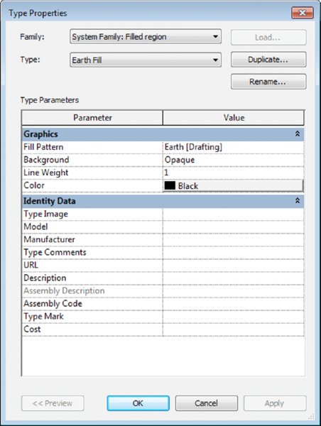
Figure 16.9 Type properties for a filled region
As we discussed in Chapter 4, filled regions can use either a drafting pattern or a model pattern. Refer to Chapter 4 for instructions on how to create a custom fill pattern. For now, let’s review the process of creating a new filled region type.
CREATING A NEW FILLED REGION TYPE
To create a new filled region type, begin by duplicating an existing region and then modify its properties. Follow these steps to get started:
- Switch to the Annotate tab in the ribbon, and on the Detail panel click Region ➢ Filled Region. Click the Edit Type button in the Properties palette.
- Click Duplicate in the Type Properties dialog box.
- Name your new region Earth Fill, and then click the button in the Fill Pattern field to open the Fill Pattern dialog box.
-
Make sure you have Drafting selected at the bottom of the Fill Patterns dialog box. Select the pattern named Earth.
Note that you can create filled region types with model patterns; however, you must make sure the region types are named clearly so you can recognize the difference between similar regions. For example, the filled region you would use to indicate brick masonry in a section is a drafting pattern (diagonal hatch), whereas a brick surface pattern is a model pattern and can be used in an elevation or plan view.
- When you finish, click OK until you exit all the dialog boxes. The same region patterns that you created for a filled region can also be associated with material surfaces or cuts by accessing the Materials dialog box from the Manage tab in the ribbon.
PLACING A FILLED REGION
Now that you have created a new filled region type, let’s add a region to the detail and explore how different boundaries can be used to create unique graphics without separate linework. If you continue from the previous exercise, the Filled Region command will still be active. If not, switch to the Annotate tab of the ribbon, locate the Detail panel, and then click Region ➢ Filled Region and follow these steps:
- In the Line Style panel in the ribbon, select Wide Lines from the drop-down menu.
- In the Draw panel of the contextual tab in the ribbon, select the Line tool and then sketch an area to the right of the slab edge at the bottom of the detail view. Use the image in Figure 16.10 as a guide.
- After you complete a closed loop of lines, hold down the Ctrl key while selecting the lines to the right and below the top line of the sketch, as shown in Figure 16.10. With multiple lines selected, go back to the Line Style drop-down menu in the ribbon and choose <Invisible Lines>.
-
Click the green check mark in the ribbon (Finish Edit Mode). The resulting filled region will look similar to the image shown in Figure 16.11.
The sketch line in the filled region boundary that is coincident with the edge of the slab should be of the same line weight as the setting for the slab. In this sample file, both Floors and Wide Lines are set to a line weight of 5.

Figure 16.10 Set some sketch boundary lines to be invisible.

Figure 16.11 The completed filled region added to the detail
Adding Detail Components
Another important tool for detailing is the detail component—a family that consists of exclusively 2D geometry. You can schedule detail components, tag them, and assign keynotes. Because they are families, they can also be stored in your office library and shared easily across projects.
To add a detail component to a view, select Detail Component from the Component drop-down list located on the Annotate tab, and use the Type Selector to choose from components that are already loaded into the model. If you don’t see a detail component you want to insert in the Type Selector, click the Load Families button in the contextual tab of the ribbon, and load one from the default library or your office library.
Remember, in the Autodesk default family library, detail components are stored in the Detail Items folder, under which the folders are organized according to MasterFormat or a similar standard coding system. Many building objects are represented in the default library with detail components. For example, if you are looking for a detail component representing a steel beam, don’t look in the library under Structural Framing—instead look in the Detail Items folder.
ADDING DETAIL COMPONENTS AND EMBELLISHING THE VIEW
We have preloaded some detail component families into the sample building project you downloaded earlier in this chapter. Use the following components to further embellish the bottom, middle, and top portions of the wall section (the metric equivalents may have an M_ prefix):
- Base Molding - Section
- Nominal Cut Lumber - Section
- Corrugated Wall Tie - Section
These detail components are all specifically designed to be used in a section detail. There are other similar detail components in the default library that can be used in a plan detail or when the object is to be shown from the side. An example of some detail embellishment is provided in Figure 16.12.

Figure 16.12 Detail components have been added to the detail view of the model.
You might notice that there are only three types loaded for the detail component family named Nominal Cut Lumber - Section. What if you need to load more types from that same family? This scenario occurs sometimes when you use families that have a type catalog. Refer to Chapter 14, “Designing with the Family Editor,” for more information about families and type catalogs.
To reload a family for access to additional types within the family, one option is to start the Detail Component tool again, click Load Family, and find that family in the library. A simpler solution is to locate the family in the Project Browser (the Families branch is toward the bottom), right-click the family name, and then choose Reload from the context menu. If the family’s source file (RFA) is available and the family has an associated type catalog, the Type Catalog dialog box will appear and allow you to select additional types to be loaded into the project.
Follow these steps:
- In the Project Browser, expand the Families branch of the tree, locate and expand the Detail Items branch, and then locate Nominal Cut Lumber-Section or M_Nominal Cut Lumber-Section.
-
Right-click the family name and select Reload from the context menu.
Note that you may be prompted to select a family file if the original RFA file cannot be located. In that case, we have provided the RFA and the accompanying type catalog in TXT format along with this chapter’s exercise downloads.
- Select the types 2 × 10 and 2 × 14 (50 × 200 mm and 50 × 300 mm) from the Specify Types dialog box, as shown in Figure 16.13, and then click OK.
- Use the additional types to continue adding detail components to the view within the floor element at the middle of the detail view.

Figure 16.13 Select types to be loaded from a family type catalog.
ARRANGING ELEMENTS IN THE VIEW
So far you have created all of the content in order and have not had to change the arrangement of any of the elements. However, knowing how to change the arrangement is an important part of detailing, so you don’t have to draw it all in exact sequence. Arrangement allows you to change the position of an element, such as a line or a detail component, relative to another element. Much like layers in Adobe Photoshop or arrangement of objects in PowerPoint, Revit allows you to place 2D elements in front of or behind others. You’ll see the Arrange panel on the far right once an element or group of elements is selected and the Modify menu appears (Figure 16.14).

Figure 16.14 The Arrange panel
From here, you can choose among four options of arrangement:
Bring To Front This brings the selected objects all the way to the front of the stack. In Figure 16.15, there are two detail lines on top of a masking region, which is also on top of a filled region. By selecting the detail lines and choosing Bring To Front, we moved the lines on top of all the other elements.

Figure 16.15 Bring To Front
Bring Forward This option brings the selected elements one step closer to the front in a given sequence. In Figure 16.16, we’ve selected the masking region and chosen Bring Forward, and now it appears on top of one of the detail lines. Note that each of the detail lines is its own layer within this stack.

Figure 16.16 Bring Forward
Send To Back This option does the exact opposite of the Bring To Front tool and will send an object all the way to the back of the stack. In Figure 16.17, we’ve chosen the masking region again and sent it to the back.

Figure 16.17 Send To Back
Send Backwards The fourth option, Send Backwards, will step the selected elements one step backward in the stack. In Figure 16.18, we’ve chosen the horizontal detail line and sent it backward; it now appears behind the filled region.

Figure 16.18 Send Backwards
Repeating Detail Component
Repeating elements are common in architectural projects. Masonry, metal decking, and wall studs are some common elements that repeat at regular intervals. The tool to help create and manage these types of elements is called the Repeating Detail Component, and it’s located in the Component flyout on the Annotate tab (Figure 16.19).

Figure 16.19 Choosing Repeating Detail Component
This tool lets you place a detail component in a linear configuration where the detail component repeats at a set interval. This allows you to draw a “line” that then becomes your repeating component. The default repeating detail is common brick depicted in section, repeating in regular courses (Figure 16.20). Creating elements like this not only lets you later tag and keynote the materials but also gives you some easy flexibility over arraying these elements manually.

Figure 16.20 A brick repeating detail
Before you create a repeating detail component, we’ll cover the properties behind one so you can get a better idea of how they work. Start the Repeating Detail Component command and draw a sample line using the Brick type. Exit the command by pressing Esc or clicking the Modify button, and then select the Brick repeating detail. In the Properties palette, click Edit Type to open the Type Properties dialog box.
Let’s review what each of these settings does:
Detail This setting allows you to select the detail component to be repeated.
Layout This option offers four different modes:
Fixed Distance This is the absolute spacing between components, for example, a strictly defined center-to-center measurement.
Fixed Number This mode sets the number of times a component repeats itself in the space between the start and endpoint (the length of the sketched path).
Fill Available Space Regardless of the value you choose for Spacing, the detail component is repeated on the path using its actual width as the Spacing value.
Maximum Spacing The detail component is repeated using the set spacing, and the number of repeated components is set so that only complete components are drawn. Revit creates as many copies of the component as will fit on the path.
Inside This option adjusts the placement of the last detail component in the repeating detail. If Inside is selected, the last component will be drawn inside the end point of the repeating detail line. If Inside is not selected, the last component will be drawn outside or overlapping the end point of the line.
Spacing This option is active only when Fixed Distance or Maximum Spacing is selected as the method of repetition. It represents the distance at which you want the repeating detail component to repeat. It doesn’t have to be the actual width of the detail component.
Detail Rotation This option allows you to rotate the detail component in the repeating detail.
In the c16-Sample-Project file, we have already created a repeating detail to illustrate brick and mortar coursing. At the base of the exterior wall, you will see that a portion of the modeled wall assembly already contains a layer assigned with a brick material; however, individual brick courses are not shown. Let’s embellish the view with a repeating detail component to better communicate the design intent.
- Zoom closer to the bottom portion of the detail view, at the base of the exterior wall. From the Annotate tab in the ribbon, locate the Detail panel, and click Component ➢ Repeating Detail Component.
-
From the Type Selector, choose the Brick repeating detail type. Starting at the bottom of the inside face of the brick layer, draw a line up to the bottom of the window sill, as shown in Figure 16.21.
If the last brick detail does not appear at the top of the sketched line, you can either drag the line farther up or edit the type properties of the repeating detail family and toggle the Inside parameter.
- Press the Esc key or click the Modify button to exit the Repeating Detail Component command. Select the corrugated metal wall tie components you placed in the Detail Components exercise. Hold down the Ctrl key while clicking each component.
- From the Arrange panel in the contextual tab of the ribbon, click Bring To Front. If necessary, you can use the arrow keys on the keyboard to nudge the wall tie components so that they display in proper relation to the mortar lines of the repeating brick detail (Figure 16.22).

Figure 16.21 The brick repeating detail component applied to the view

Figure 16.22 Adjust the draw order and position of previously placed detail components.
Although this detail still needs annotations before you can think about placing it onto a sheet, you can begin to see how you have used the 3D geometry of the model and were able to quickly add some embellishment to it to create a working project detail. For now, save this detail. You’ll return to it later in the chapter.
Using Line-based Detail Components
Although there isn’t a command dedicated to line-based detail components, this category of 2D elements can be quite powerful. As their name suggests, line-based detail components are 2D elements that behave like lines. Some examples of building elements you can illustrate with these components include waterproofing, gypsum board, plywood, and even repeating elements such as brick. Why would you use a line-based detail component for brick instead of a repeating detail component as we previously discussed? Because you can tag and schedule a line-based detail component.
You can use any modifying commands on line-based detail components such as Trim, Extend, and Align. Unfortunately, you can only draw these components in straight lines; therefore, you will need to decide whether it is more important to have tagging and scheduling capability or the ability to draw curved shapes.
In the default content library you will find components in the Detail Items folder such as Gypsum Wallboard, Rigid Insulation, and Drainage Board. Start the Detail Component command, click Load From Library, and load a few of these families. In a detail view, practice drawing these elements to embellish the modeled design further.
Drafting Insulation
The best way to think of the Insulation tool is as a premade repeating detail. You’ll find this tool on the Detail panel of the Annotate tab.
Selecting this tool allows you to draw a line of batt insulation, much like a repeating detail. Figure 16.23 shows a typical line of insulation.

Figure 16.23 The insulation detail component drafted in a view
When selecting the Insulation tool, you can modify the width of the inserted insulation from the Options bar or the Properties palette. In the Properties palette, you can also control the Insulation Bulge To Width ratio, which adjusts the amount of curve in the insulation. The default value is 2.0. By default, insulation is inserted using the centerline of the line of batt, but you can control the offset in the Options bar once the tool is activated. You can also modify the width either before or after inserting insulation into your view.
Let’s continue to embellish the wall section view in the c16-Sample-Project file. Follow these steps to begin adding insulation detail components:
-
From the Annotate tab in the ribbon, click the Insulation tool. In the Options bar, set the Width value to 5″ (150 mm) and the Offset to 0″ To Center.
You can customize the Offset value depending on how you would like to sketch the insulation by drawing the line representing the center of the insulation or either edge.
- Within the wall assembly, hover the mouse pointer at the midpoint of one of the nominal wood framing detail components you placed previously in this chapter. Use the midpoint snaps of the framing components to set the start point and end point of the insulation component.
-
Continue to add insulation components in the remaining wall, floor, and roof structure layers in the detail view.
A sample of the result is shown in Figure 16.24.
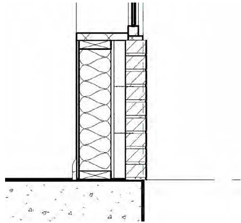
Figure 16.24 Insulation detail components added to the wall section
Creating Detail Groups
Detail groups are similar to blocks in AutoCAD and are a quick alternative to creating detail component families. They are collections of 2D graphics and can contain detail lines, detail components, or any other 2D elements. You will probably want to use a detail component to create something like wood blocking; however, if you plan to have the same configurations of wood blocking in multiple locations, you can then group those configurations and quickly replicate them in other details. As with blocks in AutoCAD, manipulating one of the detail groups will change all of them consistently.
There are two ways to make a detail group. The more common one is to create the detail elements you’d like to group, select all of them, and then click the Create Group button in the Create tab of the contextual tab of the ribbon. When you’re prompted for a group name, use a naming convention that will help you organize and recognize the contents of each group rather than accepting the default name (Group 1, Group 2, and so on).
The other way to create a detail group is by clicking the Create Group button in the Detail Group flyout on the Annotate tab (Figure 16.25). You will then be prompted for the type of group (Model or Detail) and a group name before you can select any elements for the group. If you are working in a drafting view, you can only create a detail group; the Model option is inactive in this case.

Figure 16.25 Click the Create Group button on the Annotate tab and then select the elements.
After defining a group name, you’ll be taken into Edit Group mode. Your view will have a yellow transparency overlaid on top of it, and elements within the view will appear gray. To add elements to the group, click the Add button in the Edit Group panel (Figure 16.26). Here you can also remove unwanted elements from your group. When you finish, simply click the Finish green check mark.

Figure 16.26 The Edit Group panel
You can place any group you’ve already made using the Place Detail Group button from the Detail panel of the Annotate tab (Figure 16.27) and selecting the group from the Type Selector. You can also drag and drop any group from the Project Browser into the active view.

Figure 16.27 Placing a detail group
Adding Detail Components to Families
You have read in this chapter about the number of ways you can embellish a 3D model with 2D detailing. We have discussed how to add detail elements as needed in the project environment, but you can also include 2D elements inside families. The possibilities for this method are almost limitless. You can add any kind of symbolic lines to 3D families, but in this section we will focus on nesting a detail component in a profile family, which will then become the basis for the curtain wall mullions in the sample project.
A more detailed review of curtain wall modeling is provided in Chapter 12, “Creating Walls and Curtain Walls.” For now, we will simply edit the mullions already provided in the sample building project to add some 2D detailing. Let’s get started by following these steps:
- Continue working with the
c16-Sample-Building.rvtorc16-Sample-Metric.rvtfile you downloaded from this book’s web page. In the Project Browser, locate and activate the section view named Section At Curtain Wall. It is located under the Sections (Wall Section) branch of the Project Browser. -
In the Project Browser, expand the Families branch, locate and expand the Profiles branch, and then right-click Pr-Mullion-Horizontal or M_Pr-Mullion-Horizontal. Choose Edit from the context menu and the mullion profile family will open.
The basic reference planes and profile lines have already been created.
You should already have downloaded the RFA files included with this chapter’s exercise files. Among them are a series of detail components that represent the internal extrusion details of the mullions in the sample project’s curtain wall system.
- From the Create tab in the ribbon, click the Detail Component command. Browse to the location where you downloaded this chapter’s exercise files and load the file named
Kawneer-1600-Sys1-Horizontal.rfaorM_Kawneer-1600-Sys1-Horizontal.rfa. -
Place the detail component to fit exactly within the profile boundary.
You may need to rotate the component before placing it by pressing the spacebar. The result should look like the image in Figure 16.28.
- Click the Modify button and then select the detail component you just placed in the view. From the contextual tab in the ribbon, click Visibility Settings. In the Family Element Visibility Settings dialog box, uncheck the Coarse and Medium settings. The only setting that should be checked is Fine. Click OK to close the dialog box.
- Click the Load Into Project button from the ribbon and load the revised profile family into the sample building project file. When prompted, select the option to override the existing version.
- From the View tab in the ribbon, locate the Create panel and click Callout ➢ Rectangle. In the middle portion of the wall section, sketch a rectangle around the mullion near the top of the floor associated with Level 2, as shown in Figure 16.29.
-
Double-click the callout head to activate the callout view. In the Properties palette or the view control bar, change the View Scale to 3″=1′-0″ (1:5) and set Detail Level to Fine.
After you have made these changes, you will see the nested detail component appear in the curtain wall mullion, as shown in Figure 16.30.
- Repeat the steps in this exercise for the head and sill mullion families. Edit the profile families listed here (starts with Pr-Mullion) with the associated detail components (RFA files) or their metric equivalents:
- Pr-Mullion-Head > Kawneer-1600-Sys1-Head.rfa
- Pr-Mullion-Sill > Kawneer-1600-Sys1-Sill.rfa

Figure 16.28 Detail component added to the profile family

Figure 16.29 Create a callout of the wall section.

Figure 16.30 The nested detail component will appear when Detail Level is set to Fine.
The detail components we used for this sample exercise were excerpted from real manufacturer’s content that is available for free from the Kawneer website (www.kawneer.com). Complete curtain wall system components for Revit are also available from their website.
You might have noticed that the curtain wall modeled in this chapter’s sample building is somewhat simplified. For example, the portion of the glass panels inside the mullions is not modeled; however, this condition appears in the detail component once you get down to a fine level of detail. This exercise illustrates a hybrid approach to the balance between modeling and detailing. If you download one of the Revit models from the Kawneer website (one sample, ASCMDDH3a.dwg, is provided with this chapter’s downloaded content), you will see that the glass panels are more accurately modeled to include the mullion bite (Figure 16.31). In that scenario, you would not need to include masking regions to simulate the glass panel in the mullion detail component.

Figure 16.31 More detailed modeling will require less detailing.
Reusing Details from Other Files
As you develop details of common building features, you will likely find the need to reuse this content in future projects. You might even have an existing library of details that were created in a CAD application. In either situation, there are tools and commands available in Revit software that allow you to maximize the usage of the material you produce over time.
Using CAD Details
It is quite common to have details that were originally created in a CAD program. Sometimes these are details taken from a manufacturer’s website, and sometimes they can be details drawn in other projects or from an office library, and you simply want to reuse them in your project rather than re-create them. Regardless of where they originated, you have the ability to work with 2D detail elements and import or link them into the model for use in your project.
In Chapter 7, “Interoperability: Working Multiplatform,” we provide detailed guidance on using linked DWG files for the basis of project details.
Using Details from Other Revit Projects
As we begin to discuss the reuse of detailing content, we must return to the three methodologies introduced at the beginning of this chapter—stand-alone detailing, hybrid detailing, and model detailing. As you approach a project with more detailed modeling, you will reduce the amount of drafting needed in the project environment; however, you will be less able to reuse content as standard details or detail templates. This is because the best way to reuse 2D content is with drafting views.
SAVING A SINGLE DETAIL
If you are working in a detail view of the model or a drafting view, you can save all of the 2D elements to an external file for reuse in other Revit projects. In the case of a single 2D detail, it can be quick work to get the file from one project to the next:
-
Open the file with the detail you’d like to collect, and activate the view in which this detail appears. Select all the 2D geometry and annotation within the drafting view, and create a group using the Create Group button on the contextual tab of the ribbon.
Note that if you are in a callout or detail view in which model elements are displayed, two groups will be created—a model group and a detail group.
- Give the group a name, making sure the name is unique enough not to overlap with any view names in your current project or the project you’re going to import into.
- With the detail grouped and named, expand the Groups node in the Project Browser. Now, expand the Detail Group node and find the group you just created. Right-click the group and choose Save Group from the context menu.
-
As part of the Save As process, you’ll get the Save Group dialog box (Figure 16.32). This will allow you to create a separate RVT file for your group—basically a stand-alone project file. Save the group in a location where you’ll be able to find it again and close your project file. There’s no need to name the group because the new file will reflect the group name.
We have created a sample file using this method for use in the remainder of this exercise. Make sure you download the file
c16_JambDetail.rvtfrom the book’s companion web page. - Continue with the sample building project file saved from the previous exercises in this chapter.
-
From the View tab, click Drafting View to create a new view, and name it JAMB DTL.
The scale does not matter because it will inherit the scale of the imported detail.
- From the Insert tab of the ribbon, choose Insert From File and then Insert 2D Elements From File.
- In the Open dialog box, navigate to and select the
c16_JambDetail.rvtfile. You will then see the Insert 2D Elements dialog box, which is shown in Figure 16.33. Highlight Drafting View: JAMB DTL from the list box, and select the Transfer View Scale check box. Click OK to close the dialog box and begin the import. - Click anywhere in the drafting view to place the imported elements, and then click the Finish button in the ribbon to complete the command.

Figure 16.32 The Save Group dialog box

Figure 16.33 Choose the detail group from the Insert 2D Elements dialog box.
SAVING MULTIPLE DETAILS
As you create more details in Revit projects, you will inevitably want to save some of them to an office library or some sort of localized resource so you can quickly locate the good ones again. Revit allows you to selectively save multiple views from a single project into a separate, stand-alone file. This workflow will work for both 2D and 3D content.
A quick way to get any view with 2D elements isolated to an external file is to right-click the view in the Project Browser and choose Save To New File from the context menu. Note that this option is not available for any view that does not contain 2D detail elements. It might take the software a few moments to compile the view content, but you will be presented with a dialog box asking you to locate the new file. Once the view is exported, it functions like any other RVT file. You can open these new views directly and edit or manipulate any of the content or elements within the file. You’ll also see a streamlined version of the Project Browser having only the nodes that relate to the content you’ve exported.
Another way to export multiple views is to click the Application menu and choose Save As ➢ Library ➢ View. This command allows you to save multiple views into a single RVT file that acts as a library for those views. Here are the steps:
- Start by opening the file with the views you want to save. Click the Application menu and select Save As ➢ Library ➢ View.
- This will give you the Save Views dialog box (Figure 16.34). It will show a list of view names on the left and a preview window on the right. Click the check box for each of the views you want to save into a separate file. Once you have all your view names established, click OK.

Figure 16.34 Exporting multiple views to a separate file
The software might take a few moments to export the views, depending on how many you’ve chosen and how large the overall file size is. Once the process is complete, you’ll have a separate file to import those views back into Revit projects. This import process is just as simple as exporting. Here’s how to import the views:
- Open the project where you want to put the imported views. From the Insert tab on the ribbon, choose Insert From File and then Insert Views From File.
- The new dialog box will look similar to the Save Views dialog box. You will have a list of the views you can import from the column on the left and a preview of those views on the right. Check the box for the views you want to import and click OK (Figure 16.35).

Figure 16.35 Importing multiple views into a project
You can also import entire sheets of details using this method. If sheets exist in the file you have selected with the Insert Views From File command, they are listed as options to insert. When sheets are inserted, the details placed on each sheet are automatically imported into the project as well.
The Bottom Line
Create details. Details in Revit are a combination of 2D elements layered on top of 3D model elements or sometimes just stacked on top of each other. Creating good, easy-to-read details typically requires some embellishment of the 3D model.
Master It What are the three primary categories of detail elements and how are they used?
Add detail components to families. You can make creating details in Revit easier by adding some of the detail elements directly to the family. In this way, when you cut sections, make callouts, or enlarge plan conditions, your “smart” details can begin to construct themselves.
Master It Because you don’t always want elements to appear in every scale of a view, how can you both add detail elements to your families and still limit the amount of information that is shown in any given view?
Learn efficient detailing. As you master detailing in Revit, you’ll begin to learn tips and tricks to make your process of creating details more efficient.
Master It To help you assess how much effort you should be putting into your details, what are three questions you should be asking yourself before starting any detail?
Reuse details from other files. In many project workflows, you will need to incorporate details from other projects. Reusing these details can aid in the speed and efficiency of project documentation.
Master It There are several ways to reuse details from other projects. Name one and list the steps to perform the tasks necessary to quickly move a detail from one project to another.