
10
Programming in C
Chapter Outline
- Learn C programming for 8051
- Learn the 8051 memory constitution, constants, variables and data types, arrays structures and unions, pointers, loops and decisions, functions, library functions, in-line assembly, modules and programs, presuming that the reader has prior knowledge in C and has read standard textbooks in C
- Understand the C-compilers for 8051, program build process and development tools— GNU, SDCC and Keil
- Learn the programming in C by examples
10.1 PROGRAMMING IN C
A C program consists of the following parts:
- preprocessor directives having include, define and typedef commands, global declarations and macros,
- main function and
- functions
10.1.1 Use of High-level Language Like‘C’
A high-level language like ‘C’ is used instead of assembly language programming (ALP). This is because of the following reasons:
- Enables development of a lengthy and complex program in a short time. When the appropriate compiler and development tools are available, writing more than 100 or 1000 lines of code is much less time consuming.
- Facilitates data-type declarations. It enables the use of variables and arrays simpler. Enables definitions of objects and data structures. Enables the use of data sets simpler.
- Performs the data-type check during compilation. It results in less programming errors. [Type checking means compiler gives error when a variable of specific memory type and specific data type is assigned a different value. For example, int xdata counts = “0 counts”;. The compiler will give errors. This is because the right-hand side specifies a string of characters and the left-hand side integer. Both are different data types.
- Ease in design of program-flow control structures. For example, while do, if then else, for and case statements are used. The program flows as per the decision. The decision is after the testing condition or status of variable or objects. Program flow means sequence of execution of statements or loop.
- Coding in C is not specific to a particular microcontroller family or version. The compiler must automatically take into account the instruction set of the microcontroller family or version after the appropriate preprocessor directives. [Preprocessor directives mean the commands before the processing of the program starts. A preprocessor directive starts with # sign in a C program.]
- Uses functions from the library. A library is a set of files and each file has the frequently required functions in the computations and programs. For example, mathematical functions are present in library file math.h. The program simply uses them. The program passes the input data to those functions in when they are called the program.
- Implements software abstraction.
- Implements modular programming concepts: A sources file containing a collection of functions, which are related in a program, is called a module. A module can be built by including functions from several source files. Standard functions are taken during compilation from the library in a module. A function can have in-line assembly codes.
- In-line assembly codes can be permitted. It means inserting the assembly language codes in- between. A direct hardware control is thus also feasible in C.
- Software re-usability is feasible.
- C programming can be MCU independent when the in-line assembly codes are not used and appropriate compiler for the MCU is used. The program developed for one MCU can be ported for other applications also, when the compiler supports multiple MCUs.
10.1.2 ANSI C
ANSI (American National Standards Institute) C is standard C. C99 standard of ANSI C was developed in 2000. It is the latest standard for C programming. ANSI C is supported by many popular compilers.
Many compilers for microcontrollers are ANSI C compliant and have the extensions of ANSI C and new library functions for the MCUs. They provide the additions to the ANSI C functions and data types. The extensions enable hardware-specific compilations. They take care of the data alignment in memory. They also take care of the size of the data-types in the specific MCU. A program in ANSI C when not using the hardware-specific codes compiles on any CPU or MCU or platform.
10.2 MEMORY CONSTITUTION, CONSTANTS, VARIABLES AND DATA TYPES IN 8051
10.2.1 Memory Constitution in 8051
8051 constitution has several sections of internal and external memory. When a data type is declared, the memory type of a variable can also be declared. 8051 has the following types of memory. The type can be specified when declaring a variable data type.
Memory Types
- code Memory: 8051 has program (code) memory. The addresses are from 0x0000 to 0xFFFF. 8051 has 64 kB of code memory.
- data Memory: It is directly addressable internal RAM memory for data. It gives fast access. 8051 has 128 bytes of data memory.
- idata Memory: It is indirectly addressable internal RAM memory for data. 8051 has full internal space, 256 bytes of idata memory.
- bdata Memory: It is bit addressable internal RAM memory for data. 8051 has 128 bits data memory (16 bytes between 0x20 and 0x2F).
- xdata Memory: It is indirectly addressable external RAM memory for data. 8051 has full internal space, 64 kB bytes of external data memory.
- far Memory: It is extended RAM memory spaces after 64 kB. 8051 versions, for example, Philips 80C51MX, have 8MB far memory. They are pointed by 3-byte address. (It depends on the compiler.) It is accessed by certain user-defined functions for the specific 8051 versions.
- const far: It is extended memory spaces after 64 kB. 8051 versions, for example Philips 80C51MX, have 8 MB far memory. They are pointed by 3-byte address or 24-bit DPTR register. (It depends on the compiler.) It is accessed by certain user-defined functions for the specific 8051 versions.
- pdata Memory: It is paged external data memory of 256 bytes. It can be accessed by simple instruction MOVX @R1 or MOVX @R0.
Figure 10.1 shows the memory areas used for different memory types.
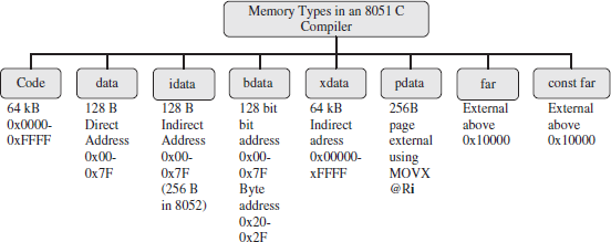
Figure 10.1 Memory Types in an 8051 C Compiler
10.2.2 Constant
A constant is one, which is assigned a fixed value, when once assigned a value, it remains fixed throughout the program. Constant is saved in RAM, if it does not change from within a program. It is advised to give names in capital letters for the constants. Constant NUMLEDS is the number of LEDs in the system. The NUMLEDS is saved in RAM.
Example 10.1
# define NUMLEDS 4 /* Four number LEDs in the system*/
Constant is saved in program memory ROM flash, if it does not change from functions in one program to functions in another program. For example, memory size of flash is constant for given hardware. The addresses of ports are also constant. The port addresses are also the same for one function to another function. These constants can be saved in flesh or ROM.
10.2.3 Variable
A variable is one that is assigned a value, which can change. It is saved at a memory address (internal or external) or register or special function register. For example, P1 = 0x10 means P1 is variable and is assigned hexadecimal value = 0x90. P1 corresponds to Port P1 of 8051. Hence, statement P1 = 0x90 when executed makes P1 port 8 bits = 10010000. Variables may be explicitly assigned to a specific memory space (by including a memory type specified in the declaration) or implicitly assigned (based on the memory model).
Example 10.2
char data portdata; /*portdata is a variable, it is explicitly assigned as of data memory type and variable data type is of a character.*/
data char portdata.; /*This is also equivalent to above acceptable in certain old-style compiler version.*/
char portdata; /*portdata is a variable, it is implicitly assigned as of data memory-type and variable data-type is of a character if memory model in the function is small memory model.*/
A value can be assigned at the address of a variable by using equal to sign and writing the value on right-hand side.
Example 10.3
char data portdata = 0x7D; /*portdata is a variable, it is explicitly assigned as of data memory type and variable data type is of a character. The variable address has the 8-bits for 0x7D. */ data char portdata. = 0x7D; /*This is also equivalent to above acceptable in certain old-style compiler versions.*/
char portdata= 0x7D; /*portdata is a variable, it is implicitly assigned as of data memory-type and variable data-type is of a character if memory model in the program is small memory model. The variable address is in internal RAM and has 8-bits = 0x7D. */
Automatic variables and arguments of a function are saved in default memory area in case they are not located in the registers.
There are two types of variables— local and global. Local variables are usable only within a function (routine). Global variables are used and their values changeable in two or more functions.
Global variables are the ones defined in preprocessor directives. The directives can define the global variables, arrays, constants, strings, pointers and port addresses.
Example 10.4
Consider a preprocessor directive:
# define bool start_switch /* It means start_switch is global and data type of it is Boolean variable. Boolean variable is a one bit variable and it can take two values—true or false (1 or 0). The bool data type is provided in SDCC (small device C compiler). */
# define long time_date /* It means time_date is a global variable of data-type as long. The long is used in SDCC as 32-bit number*/
10.2.4 Data Types
A variable or constant data can be one of the data types permissible by a compiler. C compiler may allow the following data—char (8-bit) for ASCII character, char [ ] an array of characters for a string, byte (8-bit), float (32-bit), double (64-bit double precision IEEE754 standard), unsigned short (16-bit), short (16-bit), unsigned int (32-bit) int (32-bit) and long (64-bit). [A name is a string of characters. For example, Dr. Raj Kamal is a string of 13 characters (space and full stop signs also included.)] Memory required to save the string will be 1 more than 13 = 14. String is placed a null character at the end of characters.
Let us assume that a variable time_date saves and continuously updates the time elapsed in seconds from January 1, 1970, GMT. It will be a long integer of 64 bits. It is declared as long time_date; in the program. It is assigned eight consecutive addresses. An 8-bit timer value data type is an unsigned byte. A 32-bit timer value data type is unsigned int.
There are variations in data types from one C compiler to another. Consider the following example:
Example 10.5
Small device C compiler (SDCC) allows the following data— bool (1-bit), char (8-bit) for ASCII character, char [ ] an array of characters for a string, float (32-bit, IEEE754 standard), unsigned short (16-bit), short (16-bit), unsigned int (16-bit), int (16-bit), and long (32-bit).
Figure 10.2 shows different data types in small device C compiler. An 8-bit timer value data type is unsigned char. A 32-bit timer value data type is unsigned int.

Figure 10.2 Different Data Types in Small Device C Compiler
The Bool data types supports following operations: Conjunction AND (& or *), disjunction OR (|, +), not NOT (~, !), equivalence EQV (=, ==) and exclusive or/non-equivalence XOR, NEQV (^, !=).
Use of typedef We can also define a data type using the prefix typedef. Type checking for the arithmetic and logical operations and for processing is an important feature of C or any high-level language compiler.
Use of modifiers Some integers have no sign. For example, counts; unsigned is a modifier used in such cases.
Example 10.6
char bdata statusFlags; /* statusFlags is a variable, it is of bdata memory type, and the variable data-type is of character (8-bit) */
char data x1; /*x1 is a variable, it is of data memory type and the variable data-type is of a character.*/
float idata p, q; /* p and q are two variables, they are is of idata memory type, and the data-type is of float signed IEEE754 (32-bit) */
unsigned int pdata outputdata; /* outputdata is a variable, it is of pdata memory type, and the datatype is of unsigned integer (16-bit) */
sfr
The sfr type defines a special function register (SFR). The sfr must be declared outside a function body. The 8051 devices SFR addresses are between 0x80 and 0xFF. New MX versions have an additional extended SFR space. The addresses extend in between 0x180 and 0x1FF. The address after the equal sign must be a numeric constant, not expression with operator.
Example 10.7
sfr P1 0x90; /* P1 is an SFR and the address of SFR is 0x90. */
sfr P3 = 0xB0; /* Port P3, address 0B0h */
sfr16
The sfr16 type defines a 16-bit special function register (SFR). The sfr16 must be declared outside a function body. The 8051 devices SFR addresses are between 0x80 and 0xFF. New MX versions have an additional extended SFR space. The addresses extend in between 0x180 and 0x1FF. The address after the equal sign must be a numeric constant, not expression with operator. The address must be the low byte of the 16-bit SFR.
Example 10.8
sfr16 T2 0xCC; /* T2 is an SFR of 16-bit, the lower byte TL2 is at 0xCC and higher byte at 0xCD. */
sbit
Certain SFRs have the bits, which are bit-addressable. The sbit type defines a bit within a special function register (SFR). sbit variables may not be declared inside a function. The sbit must be declared outside of the function body. It can be defined in three ways. It is shown in Example 10.9.
Three ways of specifying an SFR bit are as follows:
sbit TR0 = TCON^4; /* TR0 is SFR bit. It is b4 in TCON.*/
sbit TR0 = 0x88^4;/*TR0 is SFR bit, b4 at SFR address 0x88. Note: TCON has address 0x88.*/
sbit TR0 = 0x8C; ;/*TR0 is SFR bit at bit address 0x8C.
ANSI C99 compliant compiler SDCC 2.9.4 functions as follows: */ sbit TR1;
TR1 = ~TR1; /* TR1 =1 instead of toggling. !means NOT logic operation */.
TR1 = !TR1 /* Toggle means changing from 0 to 1 if initially 0 and 1 to 0 if initially 1. */
bit
The bit type defines a bit or flag variable. All bit variables are saved in a bit segment of 128 bits in 8051 addresses 0x20 to 0x2F bytes. The bit cannot be a pointer or an array. It can be defined as shown in Example 10.10.
Example 10.10
bit isGlowing = 0; /* The variable isGlowing is of 1-bit and at address of isGlowing, the value = 0 is assigned. */
static bit isComplete = 1; /* The variable isComplete is of 1-bit and at address of isComplete, the value = 0 is assigned. */
bit data isGlowing = 0; /* It also specifies that bit memory type is data. */
bit idata isGlowing = 0;/* It also specifies that bit memory type is idata.
ANSI C99 compliant compiler SDCC 2.9.4 functions as follows: */
bit b1; b1 = ~b1; /* It is equivalent to b1 =1 instead of toggling b1.*/
b1 = !b1; /* Toggles b1. ! is NOT logic operation sign. */
10.2.5 Static, Extern, Register and Auto Storage Classes
Some variables are static (global or used outside a function). Some are extern or register or auto.
static
A declaration ‘static int counts;’directs the compiler to assemble such that the counts are accessible outside the function block also from its address. Static variable is not pushed to stack space when there is branching call to another function. Static variable cannot be used outside the source-file, which defines the variable. It is used as global variable. It is initialized only once and not reinitialized at the entry of the function.
extern
It is global variable and is initialized in another source-module. It is initialized only once and not reinitialized at the entry of the present module.
register
The register type defines a byte. All register variables are saved in a register or registers rather than in RAM. A compiler generally prefers to save data in register in place of RAM as much as possible. A register variable can be defined as shown in Example 10.11.
register data r7 = 0xB0; /* The variable r7 is in a register. It is assigned a value = 0xB0.*/ register data TCON = 0x10; /* The register TCON is assigned a value = 0x10.*/
auto
The auto storage class is the default storage class for local variables. It is used inside a function. It is used as in Example 10.12.
Example 10.12
xdata count = 0x10C1B0; /* The variable count is at external data RAM and is assigned value 0x10C1B0. */
auto xdata count = 0x10C1B0; /* Alternative way.*/
10.2.6 Memory Models in 8051
One can consider three memory models for programming for 8051. Figure 10.3 shows these models.
Compact Model: All variables are assumed pdata, unless specified otherwise. All variables reside in a one-page 256 B of the external data memory. This memory model is used when a maximum of 256 B for variables is used and stored in external RAM of 256 B. A memory access is faster than large model but slower than small model.
Small Model: All variables are assumed idata or data, unless specified otherwise. All variables reside in 256 B or of the internal data memory. This memory model is used when variables need maximum 256 or 128B. A memory access is fastest in this model. All objects, unless specified otherwise for another memory space, and the stack must be within the internal RAM.
Example 10.13
The stack size required is 6 bytes if one function calls a routine, which calls another routine and that routine calls another routine. Each push needs 2 B of stack. Assume that the routine does not push the data on the stack. Only the program counter pushes on to stack. If there are three nested calls, then 6 B are required for stack. The variables are assigned in 256–6 = 250 B space.
Large Model: All variables are assumed xdata, unless specified otherwise. All variables reside in external data memory (64 kB). This memory model is used when a maximum of 64 kB bytes for variables are required. The data pointer (DPTR) is required to address external memory. A memory access is slowest in large model. The size of a object is limited to 64KB. It is impossible to define variables across the 64 KB address boundary.

Figure 10.3 Three Memory Models in an 8051 C Compiler
10.2.7 Stack
Classic 8051 versions provide for stack the accesses to the internal data memory. The total stack space of the classic 8051 is limited to 256 bytes. Figure 10.4(a) shows the stack space in 8051. The stack used is compiler dependent. The Keil Cx51 Compiler locates the stack area immediately following all variables in the internal data memory. The stack pointer accesses the internal memory indirectly.
Function parameters or arguments can be put in stack space in certain compilers. The stack space is not used by the function parameters or arguments in Keil Cx51 compiler. It can use all of the internal data memory up to the 0xFF limit. Cx51 Compiler provides for the use of the extended stack areas when available in new enhanced 8051 versions. The stack space is used for program counter only in Cx51. Figures 10.4(b), (c) and (d) show three different ways as to how the stack space is used and how the function parameters in stack, registers and data memory are saved.
The compiler assigns a fixed memory location for each parameter of the function. A calling function copies the arguments into the assigned memory locations for the function and then the program control transfers to the called function. The called function uses the parameters from these fixed memory locations. Keil Cx51 Compiler has a feature that passes up to three function arguments in registers by default. When a parameter is accessed from registers, the access is faster compared to when from the RAM. Cx51 compiler saves only the return address, which is on the stack space.
When interrupt occurs, the interrupt function is called. An efficient way for fast context switching is that the interrupt function uses different register banks in 8051 or in an another microcontroller. The compiler allows that interrupt functions also switch the register banks. This will require less number of values in a few registers of previously used banks on to the stack. This enhances speed performance. [Context switching means switching to new set of program counter, registers and parameters for executing the function or interrupt function.]
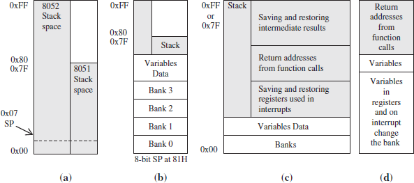
Figure 10.4 (a) Available Stack Space in 8051; and (b), (c) and (d) Three Different Ways How the Stack Space is Used and How the Function Parameters in Stack, Registers and Data Memory are Saved
10.3 ARRAYS, STRUCTURES AND UNIONS
A C program provides ease in handling of data when using the data structures. The function can be easily written when using the data structures. The example of data structures are array, struc, union, list, stack, queue, circular queue and pipe. A pipe is a data structure in which insertion (means writing and changing the pointer for the next write) is done from one function and deletion (means reading and changing the pointer to the next read) is done at the other function. Two program functions or threads are connected in some way.
List stores an item in an element along with the pointer to the next element. A tree has a hierarchical arrangement of data.
10.3.1 Arrays
Two important data structures are (a) one-dimensional array and (b) multi-dimensional arrays of the primitive data types. Following are the examples to show two data arrays
Example 10.14
Assume an unsigned integer array for 40 bytes (20 integers) received at a port. Assume SDCC compiler. The array is declared as follows: unsigned int data PortBytes [20]; The PortBytes is an array with 20 members with memory type data (direct addressable internal data memory). Figure 10.5 shows PortBytes array of integers in memory.
- Each member is saved as two-byte integer number. [The unsigned int variable requires 16-bit memory in SDCC compiler.]
- The size of array in memory = 20 × 2 B = 40 B.
- The array has a base address. Each member is at the address = (base address + i), assume that i is an unsigned integer and i can take the values = 0, 1, 2, 3, ……, or 19.
- The PortBytes [0] refers to first two bytes, The PortBytes [1] refers to third and fourth byte. The PortBytes [i] refers to (2 × i + 1)th byte and (2 × i + 2)th byte.

Figure 10.5 Port Bytes as an Array of 20 Unsigned Integers in the Memory
- The PortBytes [2 × i] refers to (4 × i + 1)th and (4 × i + 2)th bytes. The expression is permitted within square bracket provided the result of expression defines the 1st or 2nd or…… 20th member of unsigned int variable.
- The PortBytes [19] refers to last member the 39th and 40th bytes.
Assume an character array for 20 bytes received at a port. The array is declared as char data new-code[20]; The newcode is an array with 20 members with memory type data (direct addressable internal data memory). Figure 10.6 shows the newcode array in memory.
- Each member is saved as a one-byte number. [The char variable requires 8-bit memory in compiler.]
- The number can be + or −.
- The size of array in memory = 20 × 1 B = 20 B.
- The array has a base address. Each member is at the address = (base address + i], assume that i is char (ASCII Code) and i can take the values = 0, 1, 2, 3,……, or 19.
- The newcode[0] refers to first byte. The newcode[2] refers to third byte. The newcode[i] refers to (i + 1)th byte of (i + 1)th member.
- The newcode [2 × i] refers to (2 × i + 1)th byte. The expression is permitted within square bracket provided the result of expression defines the 1st or 2nd or 20th member.
- The newcode[19] refers to last 20th member and the 20th byte in memory.
Figure 10.6(a) shows how projectName [] string saves in memory. S saves as 0th byte. M saves as 19th byte. 20th byte is NULL. Figure 10.6(b) shows how 19 characters save in 20 byte address space.
String as a Variable Size Array of Characters: A string is an array of characters. The following examples show one- and three-dimensional data arrays for the strings, long and characters.

Figure 10.6 Newcode Char Array in Memory
Example 10.16
char code projectName[] = “Serial Port Program”; /* projectName is an array, it is of code memory type and the variable data-type is of character.
/*The projectName has a base address, which points to the string. */
/*The memory required by an string = number of characters plus 1 Byte. The last byte of a string corresponds to NULL character.*/
unsigned long xdata timeArray[10]; /* timeArray is an array of length 10, it is of xdata memory type, and the variable data-type is of unsigned long (32-bit). The memory required = 40 B. A long integer is of 32-bit in SDCC compiler. */
unsigned char xdata LCDData [8] [4] [2]; /* LCDData is a three-dimensional array 8x4x4 variables, it is of xdata memory type, and the data-type is of unsigned char (8-bit) or (16 bit in SDCC) */
Figure 10.7(a) shows a string projectName in memory. A string can be organized as a variable size array of characters in RAM. Figure 10.7(b) shows several strings in code memory or data memory or xdata memory. One additional string terminator will be there at the end after the array of characters. When the size of string varies, the terminator will shift at the end of the memory allocated for that string.
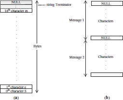
Figure 10.7 (a) Components in a String projectName at consecutive 21 addresses and (b) Storing the Messages in the Strings at Consecutive Addresses
Example 10.17
- char data str_hello_new [ ] = “Microcontroller”; The string will save at 16 addresses, 15 for microcontroller ASCII codes and 1 for the null character.
- char data str_hello_new [13]; String saves at 14 addresses. It allocates data str_hello_new [0] at an origin address for the string. str_hello_end is the last address after which a new string can start after the data at addresses str_hello_new and str_hello_end.str_hello_end address = str_hello_new+13.
- ‘H, E, L, L, O, 00H’ will change to ‘H, E, L, L, O, 20H, F, R, I, E, N, D, S, 00H’ when the string message extends from 5 characters to 13 characters. (Remember ASCII code for space is 20H. Space is also a character in between HELLO and FRIENDS in the message).
Table
A table is a two-dimensional array.
Example 10.18
A table is as follows: A table elements for x, y coordinates of edges of a rectangle are as follows:
0 0
116 0
0 120
116 120
It saves the 0, 0, 116, 0, 0, 120, 116 and 120 at consecutive memory addresses.
Hash table is two-dimensional array in which a key or pointer is used to identify an element.
Example 10.19
A hash table is as follows: Hash table elements for a telephone number table are as follows:
AaBC 197129876
ABC 375626879
DEF 541938234
PQR 823901295
AaBC in column 1 is the key. 197129876 is the value. ABC in column 1 is the key. 375626879 is the value. Hash table for telephone numbers is saved in memory as AaBC 197129876 ABC 375626879 DEF 541938234 and PQR 823901295 at consecutive memory addresses using eight strings (array of characters).
10.3.2 Struct
The structure is used to join together several variables or constants or array. A structure has a memory equal to or greater than the sum of the memory required by each member of the structure.
Example 10.20
struct {
char xdata projectName[] : “Serial Port Program:”;
char : 2;
int data rate : 9600;
} new = {“LED Blinking Program”, 4};
The structure new is used as follows: new.projectName = “LED Blinking Program; new.rate = 4. Version SDCC 2.9.4 permits that, the values in a structure may be left un-initialized. (ANSI C99 standard). For example, character is not assigned any variable name. Hence, the field for char is empty in the structure new. Previous versions did not permit this.
10.3.3 Union
A union is specified in a way similar to a struct. Union has members of different data types. It can hold data of only one member at a time. Therefore, it has a memory equal to the largest member among the members of the union. The different members share the same memory location.
Example 10.21
union serialportData {
char xdata projectName[];
char ;
int data rate;
};
/* Main function */
union serialportData new; /* Declare new union having fields and data-type members equivalent to union serialportData declared earlier. The fields were empty in serialportData. */ new.projectName = “LED Blinking Program”; /*new.projectName = “LED BlinkingProgram”*/ printf (“Project Name:%c ”, new.projectName); new.rate = 4;
.
}
10.4 POINTERS
The pointer can be understood by Example 10.22.
Example 10.22
- char *data x; /* x is pointing to a variable value and is of data memory type. The data-type is char of 8-bit. When * is present before the × then × is an 8-bit address of byte as data in internal RAM in 8051. The value is pointed by that 8-bit direct address. This is because the data type is declared as data. The declaration is as per memory type declaration new method.*/
- data char *x; /* Earlier method of memory type declaration*/
Use of Null Pointers A NULL pointer is declared in several cases.
Example 10.23
A pointer when at the last element of a list of items, is declared as NULL, ‘#define NULL (void*) 0x0000’, will declare the address 0x0000 as pointing to the null (nothing or no significant value).
Use of Pointers to Data or Function
Example 10.24
- Consider, unsigned long *time_date. It means time_date is a pointer and *time_date means contents at the address identified by the time_date.
- Consider, # define portP1 (unsigned byte *) 0x90. It means the port P1 is assigned the address 90H. *portP1 will refer to the port P1 byte, which can be assigned any value between 0 and 255. &portP1 as an argument will pass the reference to the port P1 byte and time_date + 1 will refer to the next address after the 8 bytes reserved for time_date.
Generic Pointers
Generic pointers are declared like standard C pointers. For example:
Example 10.25
- char *projectName; /* A pointer projectName, which points to set of addresses, which save the string of characters for the projectNameString “Serial Port Program:”. Pointer saves in the internal data memory of the 8051. */
- int *numTicksptr; /* A pointer numTicksptr, which points to set of addresses, which save the 16-bits for the integer variable numTicksptr. Pointer saves in the internal data memory of the 8051. */
- long *Counts; /* A pointer Counts, which points to set of 4 addresses, which save the 32-bit long integer for the counts. Pointer saves in the internal data memory of the 8051. */
Memory saves a generic pointer in Keil C51 compiler using three bytes. The pointer specifications are independent of the memory internal or external or specific location. The first byte specifies the memory type. The second byte is the high-order byte of the offset value. The byte 3 is the low-order byte of the offset value. [An address has two components: base address plus offset. Adding base + offset gives the physical address.]
Memory-specific Pointers
Memory-specific pointers always include a memory type specification is included in the pointer declaration. The pointer then saves in a specific memory type area.
Example 10.26
- char data *projectName; /* A pointer projectName, which points to set of addresses, which save the string of characters for the projectNameString “Serial Port Program”. Pointer saves in the internal data directly addressable memory of the 8051. This is because pointer memory type has now been explicitly specified. */
- int xdata *numTicksptr; /* A pointer numTicksptr, which points to set of addresses, which save the 16-bits for the integer variable numTicksptr. Pointer saves in the external idata memory of the 8051. This is because pointer memory type has now been explicitly specified. */
- long idata *Counts; /* A pointer Counts, which points to set of 4 addresses, which save the 32-bit long integer for the counts. Pointer saves in the internal idata memory (indirectly addressable memory of the 8051. This is because pointer memory type has now been explicitly specified.*/
Memory saves a memory specific pointer in Keil C51 compiler using one or two bytes. The pointer specifications are dependent of the memory internal or external or specific location. The first byte is byte address in case of data or idata, bdata or pdata or lower byte of address in case of xdata or code. The byte 2 is the high-order byte of the address in case the xdata or code is memory type specified for that pointer.
Function Pointers
The address of a function is stored in data memory. It points to the start address of the function codes. The first byte of the code is at that address.
Example 10.27
functAddr = (void *) functName;
10.5 LOOPS AND DECISIONS—CONTROL STRUCTURE CONSTRUCTS
Section 10.5.1 describes for, while do loops and repeat-until loops. Section 10.5.2 describes use of the conditions and running a block of statements as per the condition.
10.5.1 Loops
Several times the certain set of operations is repeated with some change (after increment or decrement) in value of an induction-variable. An induction variable is a variable, which induces changed status or condition in a code block. The repetition is from a certain specific value to a certain limiting value.
- A loop has a set of statements in curly brackets that execute from first statement to last.
- The values to be used in the loop are initialised before the condition test for running the loop.
- At the end of the loop (last statement), the values are changed.
- The loop starts again if looping condition is true; else the program flows to the next statement after the loop.
C provides for use of for loops in such cases.
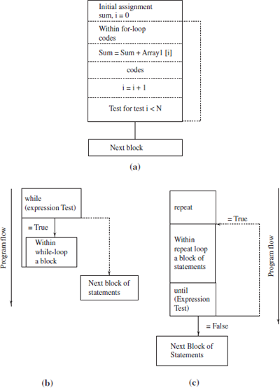
Figure 10.8(a) shows the use offor loop. Handling of the arrays or code blocks is also done by the for loop.
Example 10.28
n = 20; sum = 0; for (i = 0, i < n, i++) {sum = sum + array 1[i];}; /* the statements for finding the sum of n-terms in the array, array 1[i] with i = 0 to n−1. */
- Initial values of the variables: The first two statements make the variables n = 20 and sum = 0.
- Initial value of the looping induction variable i, the condition for continuation of loop and induction variable change before the next instance of the looping: The first term within the brackets after for, initializes the starting value of i, second term is for the end condition testing in the for loop, and third term is statement to change the i at the end of each loop. i++ in C means increments the value of i by 1. i++ means i = i + 1 and that means add the value at the address of i by 1 and place the result back at the address of i, itself.
- Statements within the loop: The statement sum = sum + array [i] is within the for loop. It runs starting from i = 0 to i = n−1. The loop run N times.
Several times certain set of operations is repeated with some changes in conditions. The operations are defined by C statements within a pair of curly brackets. The repetition is till a certain specific condition is fulfilled. C provides for use of while loops.
Figure 10.8(b) shows the use of While … do loop on left side. While … do loop means if a certain condition at a start is true then execute certain block of statements (a program section) and again test that condition and if true then again execute the program section again. As long as a certain condition is tested true, the looping continues. Loop does not execute even once if at the start itself the condition is false. The block of statements is defined by C statements within a pair of curly brackets.
Example 10.29
n = 20; sum = 0; i = 0; while (i < n) {sum = sum + array1 [i]; i++}; are the statements for finding sum of the N-terms in the array, array1 [i] with i = 0 to N−1.
- Initial values of the variables and induction variable i: The first three statements make the values of n, sum and i = 20, 0 and 0.
- Condition test for enabling execution of loop: The condition for continuation of the loop is specified within brackets after the word while.
- Statements within loop and change in condition for the next instance of the loop: The statement sum = sum + arrayl [i] is within the while loop. It runs starting from i = 0 as initially the condition i < n is fulfilled. Within the loop (statements within the curly brackets), the last statement changes the value of i before the start of the loop again after the condition-test. The condition is fulfilled as long as i remains less than n.
The block of statements defined by C statements within a pair of curly brackets can run forever. The following example shows this.
while (1) {
……;
………
} are the statements, which run for ever.
Condition for enabling execution of loop endlessly: 1 means true. The condition is never changing inside the loop. There is no induction variable used within the brackets after the while. Therefore, the condition for continuation of the loop is always be specified within brackets after the word while.
Repeat … Until … loop means test a certain condition at an end and if true then execute a certain block of statements (a program section) again from the beginning of the block, test that condition again at the end and if true then again execute the program section from repeat beginning. As long as a certain condition tested is true, the looping continues. The loop executes at least once because the condition test is at the end of the block. Figure 10.8(c) shows the use of Repeat … Until … loop.
Example 10.31
n = 20; sum = 0; i = 0; Repeat {sum = sum + array2 [i]; i++;} Until {i < n}; are the statements for finding the sum of the N-terms in the array, arrayl [i] with i = 0 to N−1.
- Initial values of the variables and induction variable i: The first three statements make the values of n, sum and i = 20, 0 and 0.
- Statements within loop and change in condition for the next instance of the loop: The statement sum = sum + array2 [i] is after the repeat command for the loop. It runs starting from i = 0 as initially the condition i < n is fulfilled. Within the loop (statements within the curly brackets), the last statement changes the value of i before the start of the loop again after the condition- test. The condition is fulfilled as long as i remains less than n.
- Condition test for enabling execution of loop: Within brackets after the word until, the condition for continuation of the loop is tested.
10.5.2 Decision Blocks
Branching of a program from a sequence of statements is often needed. C provides for the use of the decision block. A block of C statements executes when there is one decision and another when there is another decision. One of the two blocks of statements executes using if then else. A block of statements executes if a certain condition is true or else another block of statement executes. The program flow control instructions execute these. The program flow depends on whether a condition test is satisfied or not.
A program has the statements like (i) ‘If … Then … Else’, (ii) ‘Repeat … Until’ within an ‘If … Then … Else’ and (iii) CASE statements in C. Implementation of these needs N-way branching. Figure 10.9 gives the control structures for the decision blocks. Figure 10.9(a) shows three-way branching using ‘IF (expression) > 0 THEN … = 0 THEN … < 0 then ’. Figure 10.9(b) shows N-way branching as per the case using CASE (expression ) {r1: ..…; r2; ..…; ..…; ..…; rN: ..… ;}
The conditional execution of a block of C statements is used for the control structures and is given in Table 10.1. The decision blocks cause the multi-way branching.

Figure 10.9 (a) Three-way Branching Using ‘IF (Expression) > 0 THEN …; = 0 THEN … < 0 THEN ….’ (b) N-way Branching as per the Case Using CASE (Expression) {r1: …; r2; …; …; rN: … ;
Table 10.1 N-way Branching in Conditional Execution of a Block of C Statements
| Program Control Structure | Number of Branching Ways | Explanation |
|---|---|---|
IF … THEN |
Two-way branching |
If a test condition is true then branch to another address or if false then no effect and next instruction continues |
IF … THEN … ELSE |
Two-way branching |
If a test condition is true then branch to an address or if false then branch to another address. |
IF … THEN … Else if … THEN … ELSE |
Three-way branching |
If a test condition is true then branch to an address or if false test another condition if true branch to another address and if false branch to third address. |
Three-way branching |
If expression value > 0 then branch to addressl, if = 0 then to address 2 and if < 0 then to address 3. |
|
IF … THEN … ELSE IF … THEN … ELSE IF … THEN … ELSE IF … THEN ELSE IF. |
N-way branching |
If a test condition is true then branch to an address or if false test another condition if true branch to another address, if false test another condition if true branch to third address else test another condition if true branch to fourth address and so on. Total N- branching |
CASE (expression ) {r1: …; r2; …; …; rN: … ;} |
N-way branching |
Find an expression or variable value and if resulting value = ri then perform actionl and then branch out, if = r2 then perform action2 and then branch out, … if = rN then perform action N and then branch out. Branch out is when a break statement is used. |
10.6 FUNCTIONS AND LIBRARY FUNCTIONS
A routine is a set of instructions. A routine is executed as follow. The routine has a distinct start address. The program counter (PC) acquires the start address value after the earlier value of PC is saved, the instructions of the routine execute. The start address has the first instruction, which executes first in a routine. The routine has a return instruction at the end. The previously saved value of program counter is restored into the PC on the return from the routine. A routine is called function in C. A routine is called main in C, if it is the first function to execute at the beginning of a program. Each function also has a start address. Interrupt service routine is called interrupt function in C. Reentrant function is a function, which on interrupt or which on calling another function, reenters on the return to the same state of the variables and CPU registers as before the interrupt or call.
Main Function
The program source file execution starts from the main function invoked by void main (){. ;}. Before this statement, there are preprocessor directives like include. Void means that this function (program codes) does not return any variable to any other routine.
10.6.1 Function
C function has the following characteristics
- A C program consists of three parts: preprocessor directives, macros, main function and functions. Each function has a name (for identity ID). A function may have the arguments. A function may or may not return certain data or data-set or object. C function has none, one or more arguments. The arguments are within brackets.
- A standard C has declaration as follows: <[>return_type<]> functionName (<[>argu- ments<]>)
Example 10.32
- void timeSet (int numTicks). The void means function return type is void and it returns no variable or object. The name of the function is timeSet. It has one argument. It uses the integer value of numTicks as input. The numTicks is a variable. It takes the value of numTicks from outside the function. (The value is passed to the function from outside the function block.)
- int timeGet (). The int means function return type is void. The function returns value of an integer variable. The name of the function is timeGet. It gets the time using a global variable for specifying the time. There are no arguments in the function.
- A C function has a block of C statements within a pair of curly brackets. The function-statements use the local variables. The local variables are declared within the function.
- The function-statements can use the global variables also. The global variables are the ones that are declared outside the function block.
- The variables which are passed by another function are also used in the function. The variables are passed through the arguments.
A function is called from the main function or another function. There can be nested function calls also. It means one function calling second and second calling the third and so on. The return from the function is to the calling function. A function is also required to be declared in a C program. Certain compilers give a provision for the number of extensions along with the standard C declaration.
Example 10.33
Keil C51 has following provisions for the number of optional extensions along with the standard C declaration: (i) select small or compact or large memory model, (ii) declaration as a reentrant function, (iii) declaration as an interrupt function with bank switch or interrupt function declaration without bank switch. Bank-switch means a block of function statements in interrupt function (interrupt service routine) uses another register bank in 8051 than the one used by previously running function, (iv) Declare alien functions.
The examples of interrupt function declarations are as follows:
Example 10.34
- void isrFunction (void) interrupt intNum using isr_regBank { …}. This declaration means return type is void (none), function name is isrFunction, arguments required as inputs are none. It is declared as an interrupt function with interrupt number intNum and using the register bank specified by isr_regBank. [The intNum can take the value 1 or 2 or 3.The compiler generates vector address automatically from an interrupt number. The isr_regBank can take the value 0 or 1 or 2 or 3 in classic 8051.]
- void timerl interrupt 3 using 2 means timer1 is the name of interrupt function, interrupt number = 3 and it uses register bank 2.
10.6.2 Passing the parameter
A routine needs input values. Similarly, a C function needs the input values for computations. The inputs values can be passed through by two methods. One is using the arguments or by using the global variables (or objects or data structures). When the arguments are used in a function to pass the parameters, the addresses or values are passed. Two methods are used:
- Passing the value of a variable.
- Passing the reference (pointer) to a variable.
10.6.2.1 Passing a Value to an Argument
When no & sign is used in an argument of a C function or when using a variable, which is not a pointer, a variable is passed through the argument from outside the function or from the calling function on to the called function. [Passing by value must be used in arguments of a reentrant function or by the reentrant function on making a function-call.]
Example 10.35
Consider long newtime_date. The newtime_date is a global variable. This is used as a global variable because it may be input in a number of functions. Assume a function for displaying time and date is displayTimeDate (disp_time_date). When displaying the time and date, it requires the previous value of time and data disp_time_date as input and then there is no modification in this value. The input new value canbe given through argument for displaying the new time and date. A call is made through a statement displayTimeDate (newtime_date) in the calling function. The called function is void displayTimeDate (disp_time_date) {…. }. It has disp_time as local variable. The called function declares local variable long disp_time_date. It uses disp_time_date for display of time and date. The value of newtime_date is passed to disp_time_date local variable from the calling function to the called function. Any modification in value of disp_time_date in the function displayTimeDate () doe not change the newtime_date. This is because reference (address) of newtime_date is not passed in the disp_time_date in the displayTimeDate function. The value newtime_date at the calling function just copies through the argument to disp_time_date of the called functions.
Getting a value from a register takes less time in the instructions than from a data memory address. Keil Cx51 Compiler passes up to three function arguments in MCU registers. A four-byte long or float is in a quadruplet of registers. This is by default or by directive REGPARMS. It passes a long four-byte pointer in R4-R5-R6-R7 or R0-R1-R2-R3 (in case of second argument). It passes a character or 1-byte pointer in R7 (in case of first argument), R5 in case of second and R3 in case of third argument. If directive NOREGPARMS is used, then no register saves the parameters from the arguments. Bit or sbit is used as the argument in the end of the arguments list. When the first parameter of a function is a bit or sbit type, then other parameters are not passed in registers. When no registers are available for passing an argument, then the fixed memory locations are used for function parameters.
Calling a Function A calling function may pass a certain parameter to the called function. The called function can use it in a manner that its value for the purpose of calling function remains unchanged. The parameter passed is to a local variable in register bank or in internal data RAM if register space is not available. The pass-by value does not share between two or more functions (Fig. 10.10(a)).
Called Function A called function may return a parameter to the calling function. Returned value may be through a register like an accumulator or through a pointer register of a global variable. Figure 10.11(a) shows the returned value through a register like an accumulator, a scratch pad register and internal RAM for temporary storage.
10.6.2.2 Passing the References
A function has certain input and output parameters. The output parameter may be the input modified by certain operations. Using & sign in an argument of a C function, a pointer to that variable is passed through the argument and is passed from outside the function or from the calling function on to the called function. [Passing by reference is not used in arguments of a reentrant function or by the reentrant function on making a function-call.]

Figure 10.10 (a) Parameter Passed to a Local Variable. (b) Parameter Passed by Reference for a Global Variable
Example 10.36
Consider unsigned, long time_date. The time_date is a global variable. This is used as a global variable because it may be input in a number of functions. Assume a function for updating updateTime (&time_date). Updating time and date requires the previous value of time and data as input and then modify it to new time and date. The time and date after modifications are now available to other functions after the update function runs.
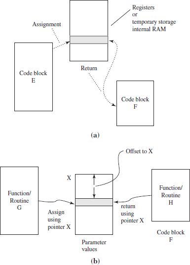
Figure 10.11 (a) Returned Value Through a Register like Accumulator, Scratch Pad Registers and Internal RAM for Temporary Storage. (b) Returned Value Maybe Through a Pointer of a Global Variable Accessed by × and Offset
The updateTime (&time_date) must use time_date address as input so that it generates new value at that address for other functions as well as itself for update at later stage. Therefore, the best way is to pass the reference (address) of time_date variable in place of the value of time and date. The update programs will update the value of time and date at that address. updateTime (&time_date) updates the time. When it is called also updates date at the called function. The time date will not save onto the stack space or data memory space of the called function, as it is a global variable.
One method is without using the & sign in an argument of a C function. Assume that outside the updateTime and updateDate functions, a declaration is made as long *time_date. A pointer to that argument is then passed on to the called function from the calling function. updateTime (time_date) is passed the address of value of time_date value.
Getting a value from a register takes less time than from a data memory address. Keil Cx51 Compiler passes up to three function arguments in MCU registers. A two-byte pointer is in a pair of registers. This is by default or by directive REGPARMS. It passes an integer two-byte pointer in R6-R7 or R4-R5 (in case of second argument) or R2-R3 (in case of third argument). It passes a generic pointer in registers R1-R2-R3 triplet. If directive NOREGPARMS is used then no register saves the parameters from the arguments. When no registers are available for passing an argument, then the fixed memory locations are used for the function parameters. Bit parameters should be declared at the end of the argument list. When the first parameter of a function is a bit type, then other parameters are not passed in registers.
Calling a Function A calling function can modify a parameter after certain operations or on certain conditions. It is also called passing the parameter by reference. The called function can use it in a manner that its value for the purpose of calling function changes as per the operations done at the called function. The parameter passed by reference is a global variable that shares between two or more functions and is used when is not possible to use direct parameter passing (Fig. 10.10(b)). Remember that global variables are always allocated in the RAM memory space. These also work as the static variables.
Called Function Figure 10.11(b) shows returned value through a pointer of a global variable.
10.6.2.3 Passing the Parameters onto Stack or Register Bank or Internal Data RAM
When the parameters cannot pass by the registers, they are passed between two functions by using internal data RAM. Local variables are allocated register bank or internal RAM or stack space as soon as a function is called and de-allocated the space on return from the function. Local variables are accessed using a pointer with constant offsets so that their addresses are always within the allocated space.
Figure 10.12(a) shows a simple way of passing of the parameters onto a stack and its use in the same function later. Figure 10.12(b) shows a complex way of passing of the parameters onto a stack and its use in the function called and in the calling function. Figure 10.12(c) shows a smooth way of passing of the parameters onto a stack at a function and its use back in the calling function.
10.6.3 Library Functions
Library means the readily available functions. Library functions are directly used by the programmer. The compiler uses the function statements from the library.
Example 10.37
Keil Cx51 compiler provides for the following library functions.
- A set of mathematical, memory, string and other ANSI standard library functions. String manipulation functions: These are used to manipulate the strings. For example, strlen () is a String manipulation library-function. It evaluates the length of the string (number of characters in a string). Memory allocation functions: These are used to allot the memory. For example, calloc () is a library-function. It allots the memory for an array from the available memory pool.
- Additional library function. For example, memcopy () is an additional library-function. This is to copy from one memory to other memory space.
- Exclusion of certain ANSI standard function. For qsort () for quick sorting of array is excluded.
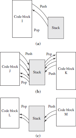
Figure 10.12 (a) Passing of the Parameters onto a Stack and its Use in the Same Function Later. (b) Passing of the Parameters onto a Stack and its Use in the Function Called and in the Calling Function. (c) Passing of the Parameters onto a Stack at a Function and its Use in the Calling Function
10.7 IN-LINE ASSEMBLY
C permits in-line assembly codes.
Example 10.38
Consider a function outportbpinv (b, p); /*b is the address of bit 1 of a port andp is the memory
address of bit n to be transferred after complementing.*/
void outportbpinv (b, p) {
asm { CPL p; MOV C, p; MOV b, C;}
};
10.8 MODULES AND PROGRAMS
A source file containing a collection of functions, which are related in a program is called a module. A module can be built by including functions from several source files. Standard functions are taken from the library in a module.
- Include Files and Header Files in the Source Files Include is a preprocessor directive to the compiler to include the contents or programs or data set from the other source or header files to build a new source file for a program. A source file has . c after its name. A header file is one, which is built by including several files. A header file has . h after its name. For example, the following C header file is the inclusion of mathematical functions from file math.h. The header files are well-tested and debugged files.
Include directive means the inclusion of the functions, files, library functions and header files.
Example 10.39
#include <string.h> is directive to include the header file having String functions during the compilation of a program.
# include <math.h> /* Include Mathematical functions*/
# include <stdio.h>” /* Include standard IO functions. For example, printf () is print function*/
# include <stdlib.h> /* Include standard library functions. For example, calloc () is memory allocation*/
# include “deviceconfig.txt” /* Include a text file for the serial device configuration, for example, for the USART or UART used chip number, bit rate or baud rate used. The deviceconfig.txt is file, which the programmer created for device configuration data. */
Keil Cx51 has INC subdirectory for including the files. It has SFR include files also.
- Macros in the Pre-processor Directives C-program can have the macros. A macro executes a named statement-block. A macro does not have functions (and thus call and return instructions) within its statement block. The compiler replaces wherever the macro names used in the C functions, by the statements at the named macro. A macro is along with the preprocessor directives in a pogram.
Example 10.40
#define PortLED_OFF (s1) s1 = 0 /* s1 is a sbit.*/or
#define PortLED_OFF () s1 = s1 & !s1 /* s1 AND operation with NOT of s1 always gives 0.! is NOT operator sign. Certain compilers use ~ sign for logic NOT operation on a Boolean variable. The bracket is optional here. However, it becomes easier to find trace the macros that are present in a program, if brackets are put without any argument variable. */
10.9 PROGRAM BUILD PROCESS AND DEVELOPMENT TOOLS
A build process for obtaining the final hex-file is as follows:
- Compiler translates the high-level language program into an object file so that it can be linked with other object files, for example, from an assembler or from another source code file.
- Linker links the relocatable object files and generates another object executable file.
- Locator prepares a final binary executable codes file by relocation of the addresses. Compiler and linkers also give the error messages.
Development Tools The development tools needed are C compiler, assembler, linker, library manager, run-time library insertion, simulator, and debugger. Development tools are available from a number of sources. For example, three popular sources are Keil, Germany, (now an ARM@ company) IAR Systems, Sweden, Avocet Systems Inc, USA.
A typical 8051 simulator and debugger consists of the following—(a) simulation of the IOs, (b) simulation of interrupts, (c) source and assembler language debugger, (d) powerful handling of the breakpoints, the points where the critical examination of variables, or registers are checked and (e) macro-type commands for debugging. Chapter 12 will describe the development tools in detail. Keil C51 microcontroller development tools will also be described in Chapter 12
10.10 C COMPILERS—GNU, SDCC AND KEIL
8051 has many derivatives of the classic 8051 devices. The derivates and IP cores are made by Analog Devices, Atmel, Cypress Semiconductor, Dallas Semiconductor, Goal, Hynix, Infineon, Intel, NXP (founded by Philips), OKI, Silicon Labs, SMSC, STMicroelectronics, Synopsis, TDK, Temic, Texas Instruments and Winbond. [IP core means an intellectual property files for a specific VLSI circuit or processor or device, which can be put on to the silicon chip using those files at the foundry after integrating with other files.] A C compiler compiles provided the specific derivative or version of MCU is supported by that compiler.
10.10.1 GNU Tools
GNU development tools are the free software (FSF) that can be downloaded from the net. GNU C/C++ compiler is called gcc (GNU compilers collection). GNU C/C++ assembler is called as. GNU C/C++ linker is called ld, respectively. GNU linker also provides the scripting. [Script means piece of program code, which is interpreted at run time step by step. That enables control of the object file. GNU debugger and simulation tools are also FSFs.
Two popular Web sites for learning the GNU development tools are http://www.st-andrews.ac.uk~iam/docs/tutorial.html and http://www.amath.washington.edu/~lf/tutorials/autoconf/tutorial_oc.html. It is authored by Eleftherios Gkioulekas. It introduces the GNU build system. It shows how to use it and write good code. It explains a GNU source code navigator Emacs. It explains Texinfo. GNU build system editing is by Emacs/Viflamewar. It explains configuration and navigation through the software using Emacs. It explains how to compile using the makefiles built by the program developer. Building of the libraries is described. It explains how to install the system. It explains a utility gpl.
GNU build system primary tools are as follows—(a) Autoconf. It generates a configuration shell script, named configure. It evaluates the installer platform for portability. This information customises the makefiles, configuration header files, and other application specific files. It uses the generic templates. Programmer using autoconf does not need to customise the files. (b) Automake requires Autoconf. It generates the makefile templates and Makefile.in (for Autoconf) from a specification file called Makefile.am. Automake-generated makefiles conform to the GNU makefile standards. (c) Libtool compiles the location independent code. It independently builds shared libraries and enables their porting.
The GNU build system simplifies the development of portable programs and enables simple building of the source code programs. Program developer can give more attention to the debugging of the source code. Installer compiles and instals the program directly from the distribution source code. The GNU build system tasks are as follows—(a) automatic configuration, (b) auto makefile generation, (c) building multi-directory packages and (d) automatic distribution building by running make distcheck. Two popular Web sites are www.scs.cs.nyu.edu/~reddy/links/gnu/tutorial.pdf and http://www.programmer-sheaven.com/zone5/cat780/.
10.10.2 SDCC Compiler
SDCC (Small Device C Compiler) is free open source, optimizing ANSI-C compiler. The entire source code for the compiler is distributed under GPL. SDCC has latest version SDCC 2.9.4 since December 2009. It is freely downloadable from Web site http://sdcc.sourceforge.net/snap.php. It has been designed by Sandeep Dutta.
It is downloaded from the SDCC subversion repository or alternately from the snapshot builds http://sdcc.sourceforge.net/snap.php. SDCC is distributed with all the projects, workspaces, and files. It is usable with Visual C++ 6.0/NET (except for SDCDB (SDCC debugger) and ucSim (SDCC simulator).
SDCC user guide is at Web site http://www.sdcc.sourceforge.net/doc/sdccman.pdf SDCC uses ASXXXX a free open source retargetable assembler. It uses ASLINK linker. SDCC has extensive language extensions suitable for utilizing various microcontrollers and underlying hardware effectively. It has plug-in support for Eclipse RTOS (http://sourceforge.net/projects/eclipse-sdcc).
The SDCC features are as follows:
- Designed for Intel MCS51 based MCUs (8031, 8032, 8051, 8052, etc.), Dallas DS80C390 variants, Freescale (formerly Motorola) HC08 and Zilog Z80 based MCUs. SDCC can be retargeted. It can be retargeted for other MCUs. Its support to Microchip PIC, Atmel AVR is under development.
- Has MCU specific and loop optimizers and has dead code eliminator. [Loop optimization is done by loop reversing and reducing strength of the induction variable. If an induction variable is declared as int data type but does not take int range values but takes only unsigned char values, then it is converted to unsigned char data type. This reduces the strength for optimization purpose. Dead code eliminator means the functions, macros and the statements, which are declared but is not used in the source files are eliminated.]
- Has peephole optimizer. It uses a rule-based substitution mechanism. The mechanism is MCU independent. [Peephole means peeping into the operation and modifying it into simpler operations. For example, multiplication can be reduced to shifts and additions. y = 5 × x is reduced to temp1 = shift x left by 2 and y = temp1 + x. [Left shift of × by 2 means multiplication by 4.]
- Has global sub-expression elimination,
- Supports seven basic data types, including 32-bit IEEE floating-point and sbit, sfr, sfr16, sfr32.
- Supports flexible variable allocation using bit, data (near), bdata, idata, xdata (far), and pdata memory types.
- Allows inline assembler code
- Has companion source level debugger SDCDB. The debugger uses ucSim. ucSim is a free open source simulator for 8051 and other MCUs.
- Supports constant folding and propagation, copy propagation, jump tables for switch statements. [Constant folding means constants occurring together in an expression are combined to another constant. For example, #define pi 3.141 and in a function 2 × pi will be folded to 6.242 at the compilation.]
- Presently does not have code banking support for MX derivatives of 8051.
10.10.3 Keil C compiler Cx51
Keil™ an ARM® company offers the 8051 C compiler. It is called Cx51. It is for the 8051 and its derivatives. The Cx51 Compiler allows writing of the 8051 microcontroller applications in C. The executable file gives the efficiency and speed, which are near to the assembly language programs. There are several language extensions in the Cx51. It enables full access to all resources of the 8051 or its derivative.
The C51 Compiler translates C source files into relocatable object modules. The modules have full symbolic information. That enables debugging of the object files with the μVision Debugger or an incircuit emulator. The Cx51 also generates a listing file. This can be included in the symbol table and cross reference information.
The Cx51 features are as follows:
- Supports nine basic data types, including 32-bit IEEE floating-point. There is efficient calculation during float variable operations.
- Supports flexible variable allocation using bit, data, bdata, idata, xdata, and pdata memory types. Supports memory allocation and relocation functions, memory freeing functions and user-defined heap sizes. [Heap is the run-time output data in RAM.]
- Enables interrupt functions in C.
- Enables full use of the 8051 register banks.
- Has 8051 specific optimizer. This optimizes the codes.
- Supports design of the reentrant functions. It solves the critical section interrupt problems with the shared data among the functions.
- Enables complete symbol and type information when debugging at the source-level.
- Enable use of AJMP and ACALL instructions [ACALL and AJMP are 8051 instructions in which only 11-bits of program counter are specified. The instruction becomes of 2 bytes length in stead of 3].
- Supports bit-addressable data objects.
- Supports constant folding, loop optimizers, dead code eliminator, reduction of strength and peephole optimizer.
- Uses a rule-based substitution mechanism. The mechanism is MCU independent.
- Has built-in interface for the RTX51 Real-Time Kernel.
- Supports dual data pointers on Atmel, AMD, Cypress, Dallas Semiconductor, Infineon, Philips, and Triscend microcontrollers.
- Supports many 8051 family versions and derivatives, 8051 Extended and 8051 MX Philips 8xC750, 8xC751, and 8xC752 limited instruction sets MCUs,
- Supports the Infineon 80C517 arithmetic unit.
- Supports popular emulators.
10.11 COMMENTS, SIGNS AND NAMES IN C PROGRAMS
Use of Comments in C Program Source File
C program is easily understood by the use of the comments after a command or statement or before the start of a block of statements or loop or condition test. A comment starts with /* (slash and star) sign and ends with */ (star and slash sign). Comments explain the meaning of a statement or statement-block.
The comments in a line can have // (double slash) sign after the statement. This is when only the start of a comment is specified. The end is implicit by end of the line.
A compiler ignores the characters before the comment end sign */ or after the /* or // sign. Compiler also ignores the tabs, spaces (other than the ones in the Strings) and new line character. [New line character is not visible on the screen.]
Example 10.41
# define NUMPORTS 4 /* Four number of ports in the system*/
or
#include <reg51.h> // Include in the source file the header file for 8051 registers
# define NUMPORTS 4 // Four number of ports in the system
Use of the Statement Separators and Set of Statements
Sign ; (semi-colon) is used as a statement separator. It separates one statement from another. A statement block has a set of statements. The statements in a block or set start from opening curly bracket and end with closing curly bracket.
Names Chosen for the Variables, Pointers and Functions
The x or y or z or k or v2 or any other multi-character or single character name can be chosen for the variable port byte, provided it starts with an alphabet, not with a number and provided it does not have any special character or sign or is not same as the set of characters which define the keywords in a program or compiler. The examples of the keywords are for or while or case or if or then.
A good practice is that the name of the variable or pointer or function or array or data-structure or object is chosen such that the name itself implicitly explains the use of that entity in the source file.
- Constants can be named with all capital case characters. For example, NUMPORTS.
- The function, which returns the result of a condition check, can start with is. For example, is- StackEmpty or is stackFull.
- The function, which returns the result of the value of some parameter or calculations, can end or start with get. For example, timeGet or gettime or getNumTicks or numTicksGet.
- The function, which sets the result of the value of some parameter or calculations, can end or start with set. For example, timeSet (time) or settime (time)or setNumTicks (numTicks) or numTicksSet (numTicks). The time is a variable for time, which is set by the function. numTicks is a variable for time, which is set by the function.
10.12 PROGRAMMING EXAMPLES FOR PORTS
Following subsections give the program examples for the ports.
10.12.1 Using all 8-bits of Port Simultaneously
8051 has four number 8-bit ports, P0, P1, P2 and P3. If all the 8-bits are to be used then the data type of a variable used for assigning a byte to the port is declared as unsigned character. Ports P0, P1, P2 and P3 are the SFRs in 8051.
Preprocessor directive is include reg51.h header-file. The file is for the registers (SFRs) in the source file. The reg51.h file provides the related SFR declarations of the data type, addresses, pointers and operations during the compilation of the source file. Remember that a preprocessor directive starts with a # sign.
The following examples show how these ports are written (sent the data), how the byte at a port is modified or how each bit is toggled (Each bit 1 changed to 0 or 0 by 1), how these ports are read input byte in a program, and how the alternate bits are made complimentary to each other.
Program Example 10.1: Program to write 0x75 at port P0.
#include <reg51.h> /* Include header file for the registers and SFRs of 8051. */
void main (void) /* main function needs no arguments (inputs) and is not returning any data or data structure or data-object*/
{ /* Curly bracket at start of the statement-block for the main function*/
unsigned char portByte; /* Declare the portByte as variable to save the port data at the address of the variable. */
portByte = 0x75; /* portByte variable is assigned the value= 01110101 */
P0 = portByte; /* P0 is assigned (written) the value of portByte */
/*When the above program in a source file is compiled and run using a simulator, the simulator shows that P0 become 0x75. The port P0 bits b7, b6, b5, b4, b3, b2, b1 and b0 become equal to 01110101. Assume an LED each is connected through an interfacing circuit such that when a bit bn = 0, the corresponding LED is OFF and when = 1 then ON. The 0th, 2nd, 4th, 5th and 6th LEDs become ON and 1st, 3rd and 7th LEDs will be OFF at P1. */
} /* Closing curly bracket at end of the statement-block for the main function*/
Program Example 10.2: Program to complement all bits at port P1. [Means toggle all bits.]
#include <reg51.h> /* Include header file for the registers and SFRs of 8051. */
void main (void)
{
P1 = ~ P1; /* We may need statement P1 = ! P1 for the NOT operations on each bit, then the P1 is assigned the value of complement of P1 in new C99 ANSI compliant compiler. */
/*When the above program in a source file is compiled and run using a simulator, the simulator shows that P1 = NOT (P1). The port P1 bits b7, b6, b5, b4, b3, b2, b1 and b0 equals to complement of the earlier bits. Assume an LED each is connected through an interfacing circuit such that when bn = 0, the corresponding LED is OFF and = 1 then ON. When this statement runs, all LEDs become = OFF if earlier they were ON and all those LEDs become = ON when this statement runs if earlier they were OFF at P1. */
}
Program Example 10.3: Program to reset all bits at port P1.
#include <reg51.h> /* Include header file for the registers and SFRs of 8051. */
void main (void)
{
P1 = P1 & ~ P1; /* For new C99 ANSI compliant compiler use P1 = P1 & ! P1. A variable AND operation on the NOT of variable, makes the variable = 0.
P1 becomes 0x00 after this statement runs. */
/*When the above program in a source file is compiled and run using a simulator, the simulator shows that P1 = 00000000 after the run. The port P1 bits b7, b6, b5, b4, b3, b2, b1 and b0 equal 00000000. Assume an LED each is connected through the interfacing circuit such that when bn = 0, the corresponding LED is OFF and = 1 then ON. All bits become = 0 when this statement runs, and all LEDs at P1 becomes OFF at P1. */
Program Example 10.4: Program to set all bits at port P2.
#include <reg51.h> /* Include header file for the registers and SFRs of 8051. */
void main (void)
{P2 = P2 & ~ P2 ; /* Use P2 = P2 & ! P2 in case of new C99 ANSI compliant compiler */.
P2 = ~ P2; /* New C99 ANSI compliant compiler needs P0 = ! P2. */
/* First statement made P2 = 0x00 and second made P2 =0xFF. When the above program in a source file is compiled and run using a simulator, the simulator shows that P2 first 0x00 and then = 0xFF. The port P2 bits b7, b6, b5, b4, b3, b2, b1 and b0 equals 00000000 after first statement and 11111111 after the second statement. Assume an LED each is connected through the interfacing circuit such that when bn = 0, the corresponding LED is OFF and = 1 then ON. All bits become 1 when these 2 statements run, and all LEDs become ON at P2. */
}
Program Example 10.5: Program to read input at the port P0.
#include <reg51.h> /* Include header file for the registers and SFRs of 8051. */
void main (void) /* main function needs no arguments (inputs) and is not returning any data or data structure or data-object*/
{/* Curly bracket at start of the statement-block for the main function*/
unsigned charportByte; /* Declare the portByte as variable to save the port data at the address of the variable. */
portByte = P0; /* portByte variable is read the value from address of P0.*/
} /* End*/
Program Example 10.6: Program to reset all even bits and set all odd bits at port P2.
#include <reg51.h> /* Include header file for the registers and SFRs of 8051. */
void main (void)
{
unsigned char portByte; /* Declare the portByte as variable to save the port data at the address of the variable. */
portByte = 0xAA; /* portByte variable is assigned the value= 10101010 */
P2 = portByte; /* P2 is assigned the value of portByte */
/*When the above program in a source file is compiled and run using a simulator, the simulator shows that P2 = 0xAA. The port P2 bits b7, b6, b5, b4, b3, b2, b1 and b0 equals 10101010. Assume an LED each is connected through the interfacing circuit such that when bn = 0, the corresponding LED is OFF and = 1 then ON. The 0th, 2nd–4th, and 6th LEDs will be OFF and 1st, 3rd, 5th and 7th LEDs will be ON at P2. */
}/* End of main function*/
Program Example 10.7: Program to reset all odd bits and set all even bits at port P3.
#include <reg51.h> /* Include header file for the registers and SFRs of 8051. */
void main (void)
unsigned char portByte; /* Declare the portByte as variable to save the port data at the address of the variable. */
portByte = 0x55; /* portByte variable is assigned the value= 01010101 */
P3 = portByte; /* P3 is assigned the value of portByte */
/*When the above program in a source file is compiled and run using a simulator, the simulator shows that P3 = 0x55. The port P3 bits b7, b6, b5, b4, b3, b2, b1 and b0 equals 01010101. Assume an LED each is connected through the interfacing circuit such that when bn = 0, the corresponding LED is OFF and = 1 then ON. The 0th, 2nd–4th, and 6th LEDs will be ON and 1st, 3rd, 5th and 7th LEDs will be OFF at P3. */
} /* End */
Program Example 10.8: Program to toggle twice each bit at port P2 with in-between delay. Set delay by 10000 no-operations in between using for loop.
Assume odd and even bits are always complementing each other.
#include <reg51.h> /* Include header file for the registers and SFRs of 8051.*/
void main (void) /* main function needs no arguments (inputs) and is not returning any data or data structure or data-object*/
{
int i; /* declare i as integer variable */
int n = 10000;/* declare n as integer variable and assign it value = 10000*/
unsigned char portByte; /* Declare the portByte as variable to save the port data at the address of the variable.*/
portByte = 0x55; /* portByte variable is assigned the value = 01010101.*/
P2 = portByte; /* P3 is assigned the value of portByte */ for (i = 0; i < n; i++) {;}; /*For i = 0 to n-1, run the loop with no-operations for introducing delay. */ portByte = 0xAA; /* portByte variable is assigned the value= 10101010 */
P2 = portByte; /* P2 is assigned the value of portByte */
/* End of statements*/
/*When the above program in a source file is compiled and run using a simulator, the simulator shows that P2 = 0x55, then there is delay. The wait is till i = 10000 . Then the P2 becomes 0xAA. The port P2 bits b7, b6, b5, b4, b3, b2, b1 and b0 equals 01010101 before the wait loop and 10101010 after the loop. The simulator finds the time taken in between two successive changes. The variable n can be defined as per the desired time interval between toggling of byte value or even and odd bits. Assume an LED each is connected through the interfacing circuit such that when bn = 0, the corresponding LED is OFF and = 1 then ON. The 0th, 2nd- 4th, and 6th LEDs will be ON and then OFF. 1st, 3rd, 5th and 7th LEDs will be OFF and then ON. There will be wait between two states of the port P2.*/
} /* End of the main function*/
Note: There is a better method and alternative than the wait loop. Use the interrupt function and timer T0 or T1 (Section 10.13).
Program Example 10.9: Program to toggle endlessly each bits at port P2 with in-between delay. Set delay by 10000 no-operations in between using for loop.
Assume odd and even bits are always complementing each other.
#include <reg51.h> /* Include header file for the registers and SFRs of 8051.*/
{
int i; /* declare i as integer variable*/
int n = 10000; /* declare n as integer variable and assign it value = 10000*/
unsigned char portByte; /*Declare the portByte as variable to save the port data at the address of the variable.*/
while (1) { /* Use the while loop and expression such that it is always true for endless looping.*/ portByte = 0x55; /* portByte variable is assigned the value= 01010101*/
P2 = portByte; /* P2 is assigned the value of portByte */
for (i = 0; i < n; i++) {;}; /*For i = 0 to n−1, run the loop with no-operations*/
portByte = 0xAA; /* portByte variable is assigned the value= 10101010*/
P2 = portByte; /* P2 is assigned the value of portByte*/
for (i = 0; i < n; i++) {;}; /*For i = 0 to n−1, run the loop with no-operations*/
} /* End of while loop statements*/
/*When the above program in a source file is compiled and run using a simulator, the simulator shows that P2 = 0x55, then there is delay and wait till i = 10000 . Then P2 becomes 0xAA. Again there is delay and wait till i = 10000. The port P2 bits b7, b6, b5, b4, b3, b2, b1 and b0 equals 01010101 before the wait loop and 10101010 after the loop. Again there is wait. The simulator finds the time taken in-between two successive changes. The n can be assigned as per the desired time interval between toggling of byte (toggling of even and odd bits). Assume an LED each is connected through the interfacing circuit such that when bn = 0, the corresponding LED is OFF and = 1 then ON. The 0th, 2nd, 4th, and 6th LEDs will be ON and OFF alternately. 1st, 3rd, 5th and 7th LEDs will be OFF and ON alternately. There will be wait between two states of the port P2 and endless repetition of these two states.*/
} /* End of the main function*/
The LEDs in the above examples can be replaced by any other device. The device can be motor, relay, inductive coil, furnace, music instrument. An appropriate interfacing circuit needs to be designed for the device.
10.12.2 Using Individual Port Bit
8051 has four number 8-bit ports, P0, P1, P2 and P3 and each port bit is also addressable. Px^n refers to bit bn of Px and thus to pin Px.n state, where x = 0 or 1 or 2 or 3 and n = integer between 0 and 7.
Example 10.42
P0^1 refers to bit b1 of P0 and thus to pin P0.1 state. P0^1 refers to bit b1 of byte at address 0x80.
P0^1 also refers to bit at address 0x81.
When preprocessor directive include <reg51.h> header-file is used for the registers (SFRs) in the source file, then the reg51.h file provides the related SFR declarations. For example, the declaration sbit P0^7 already exists in reg51.h for pin 7 state at P0. The declaration sbit EA = IE^7 already exists in reg51.h. The declarations for the addresses of EA, IE, P0 already exist in reg51.h.
The following examples show how a bit at a port is written (sent the data), how the bit at a port is read or how a bit at port complemented and how at the port the bit is toggled. An interfacing circuit, a port pin, for an LED shows the state 0 or 1 of the port pin by the LED OFF or ON. The LED in the examples can be replaced by any other device. The device can be motor, relay, inductive coil, furnace, music instrument. An appropriate interfacing circuit needs to be designed for the device.
Program Example 10.10: Program to write 1 at fifth pin of P1.
#include <reg51.h> /* Include header file for the registers and SFRs of 8051. */
sbit portBit = P1A; /* declare variable portBit address as the fifth bit address in SFR P1. */
void main (void)
{
portBit = 1; /* Assign value = 1 at address of portBit */
/*When the above program in a source file is compiled and run using a simulator, the simulator shows that P2 bit 4 resets. */
} /* End of the main */
Program Example 10.11: Program to write 0 at fourth pin of P2.
#include <reg51.h> /* Include header file for the registers and SFRs of 8051. */
sbit portBit = P2^4;/*declare variable portBit address as the fourth bit address in SFR P2. */
void main (void)
{
portBit = portBit & /portBit; /* Assign value = 0 at address of portBit */
/*When the above program in a source file is compiled and run using a simulator, the simulator shows that P2 bit 4 resets. */
}
Program Example 10.12: Program to complement third bit of P3.
#include <reg51.h> /* Include header file for the registers and SFRs of 8051. */
sbit portBit = P3A;/*declare variable portBit address as the third bit address in SFR P2. */
void main (void)
{
portBit = ~portBit; /* portBit = !portBit in ANSI C99.Assign value = 0 at address of portBit if 1 else 1 if 0*/
/*When the above program in a source file is compiled and run using a simulator, the simulator shows that P3 bit 3 complements, 0 of 1 and 1 of 0 initially. */
}
Program Example 10.13: Program to toggle second bit of P2.
#include <reg51.h> /* Include header file for the registers and SFRs of 8051. */
sbit portBit = P2^2;/*declare variable portBit address as the second bit address in SFR P2. */
void main (void)
{
portBit = ~portBit; /* portBit = !portBit in ANSI C99.Assign value = 0 at address of portBit if 1 else 1 if 0*/
/*When the above program in a source file is compiled and run using a simulator, the simulator shows that P2 bit 2 toggels, 0 of 1 and 1 of 0 initially. */
}
Program Example 10.14: Program to toggle twice second bit of P2 with in-between delay between two successive states.
Set delay by doing no operations 10000 times using a loop.
#include <reg51.h> /* Include header file for the registers and SFRs of 8051.*/
sbit portBit = P2A2;/*declare variable portBit address as the second bit address in SFR P2. */
void main (void)
{
int i, /* declare i as integer variable */
int n = 10000, /* declare n as integer variable and assign it value = 10000 */
portBit = ~portBit; /* portBit = !portBit in ANSI C99.Assign value = 0 at address of portBit if 1 and 1 if 0*/
for (i = 0; i < n; i++) {;}; /*For i = 0 to n- 1, run the loop with no-operations*/
portBit = ~portBit; /* portBit = !portBit in ANSI C99. Assign value = 0 at address of portBit if 1 and 1 if 0*/
/*When the above program in a source file is compiled and run using a simulator, the simulator shows that P2 bit 2 = 0, then there is delay and wait till i = 10000. Then P2A2 becomes 0. Again there is delay and wait till i = 10000. The simulator finds the time taken in-between two successive changes. The n can be assigned as per the desired time interval between toggling of bit.*/
}/* End of while loop statements*/
Program Example 10.15: Program to toggle endlessly 0th bit of P2 with in-between delay between two successive states. Set delay by doing no operations 10000 times using a loop before changing to a new state.
#include <reg51.h> /* Include header file for the registers and SFRs of 8051. */
sbit portBit = P2A0;/*declare variable portBit address as the second bit address in SFR P2. */
void main (void)
{
int i, /* declare i as integer variable */
int n = 10000, /* declare n as integer variable and assign it value = 10000 */
while (1) { /* Use the while loop and expression such that it is always true for endless looping.*/
for (i = 0; i < n; i++) {;}; /*For i = 0 to n−1, run the loop with no-operations*/
portBit = ~portBit; /* portBit = !portBit in ANSI C99. Assign value = 0 at address of portBit if 1 and 1 if 0*/
for (i = 0; i < n; i++) {;}; /*For i = 0 to n−1, run the loop with no-operations*/
portBit = ~portBit; /* portBit = !portBit in ANSI C99. Assign value = 0 at address of portBit if 1 and 1 if 0*/
}/* End of while loop statements*/
/*When the above program in a source file is compiled and run using a simulator, the simulator shows that P2 bit 0 = 0, then there is delay and wait till i = 10000. Then P2^0 becomes 1. Again there is delay and wait till i = 10000. The port P2^0 equals 0 before the wait loop. It becomes 1 after the loop. Again there is wait. The simulator finds the time taken in-between two successive changes. The n can be assigned as per the desired time interval between toggling of bit. Assume an LED each is connected through the interfacing circuit such that when bn = 0, the corresponding LED is OFF and = 1 then ON. The 0th LED will be ON and OFF alternately. The 0th LED will be OFF and ON alternately. There will be wait between two states of the port bit P2^0 and endless repetition of these two states. */
}/* End of the main function*/
Program Example 10.16: Program to write 0 at sixth and first pin of P0 and third pin of P2.
#include <reg51.h> /* Include header file for the registers and SFRs of 8051. */
sbit port2Bit3 = P2^3;/*declare variable portBit address as the fourth bit address in SFR P2. */
sbit port0Bit6 = P0^6;/*declare variable portBit address as the fourth bit address in SFR P2. */
sbit portOBitl = P0^1;/*declare variable portBit address as the fourth bit address in SFR P2. */
void main (void)
{
/* Assign value = 0 at addresses of port bits */
port0Bit6 = 0; port0Bitl = 0; port2Bit3 = 0;
/*When the above program in a source file is compiled and run using a simulator, the simulator shows that P0 bit 6 resets, P0 bit 1 resets and P2 bit 3 resets. */
}/* End of the main function*/
10.13 PROGRAMMING EXAMPLES FOR TIMERS
Refer Section 3.5.1 and Table 3.2.
- There are two timers, T0 and T1. TH0, TL0, THL1 and TL1 for holding time/count values. 8052 version has three timers T0, T1 and T2 and six registers TH0, TL0, THL1, TL1, TH2 and TL2 for holding bytes for the time/count values.
- An SFR, which controls the timer T0 and T1 functions, is TCON. It also has the status for T0 and T1.
- An SFR, which defined modes of the timer T0 and T1 functions, is TMOD.
- An SFR, which controls the timer T0 and T1 functions, is T2CON, has status bits for T2 and selects the functions of T2.
Programming a timer means programming the TCON and TMOD bits and loading the appropriate count variable c0 as per the intervals of the clock inputs deltaT to the timer/counter.
Programming the TH0, TL0, THL1 and TL1
8051 has an 8-bit register, TMOD. A bit of TMOD is not bit-addressable. Therefore, the complete byte is written into TMOD at an instance. The data type of a variable used for assigning a byte to the time/ count holding SFR is declared as an unsigned character.
8051 has an 8-bit register, TCON. A bit of TCON is bit-addressable. Therefore, each bit or complete byte is written into TCON at an instance. The data type of a variable used for assigning a bit to the time/ count holding SFR is declared as sbit.
8051 has four number 8-bit registers, TH0, TL0, THL1 and TL1. A bit of any of these is not bit- addressable. When using 8-bit timer modes, all the 8-bits are to be used separately. The data type of a variable used for assigning a byte to the time/count holding SFR is declared as an unsigned character.
When using 16-bit timer mode, all the 16-bits are to be used simultaneously. A variable used for assigning the time/count holding SFR pair (TH0-TL0 or TH0-TL0) has the data type of short (16-bit) or int (16-bit).
The following examples show how the timers are written (programmed), how a preset delay is produced between the start of the timer and execution of the ISR and how the pulses can be generated at a port pin.
(1) Specifying the Modes for T0 and T1
Program Example 10.17: Program to specify the 4-bits of timer T0 mode 2:
- For specifying gate input active-inactive for external control of start/stop of TO = inactive.
- For timer using internal clock or for external count inputs= internal clock inputs (timer)
- For specifying timer mode = 2.
#include <reg51.h> /* Include header file for the registers and SFRs of 8051. */
void main (void)
{ /* 3rd bit b3 is GATE_T0, 2nd bit b2 is C_T0, 1st and 0th bit-pair is for specifying mode */
TMOD = 0x02; /*Assign the timer T0 start-stop external gate pin inactive, timer T0 using internal clock inputs and timer T0 mode = 2*/
/*Mode 2 of T0 means TH0 loads automatically into TL0 after each overflow. TL0 does 8-bit counting from loaded value to overflow. */
} /* End of the main function*/
Program Example 10.18: Program to specify the 4-bits of timer T1 mode 1:
- For specifying gate input active-inactive for external control of start/stop of Tl = inactive.
- For timer using internal clock or for external count inputs= Tl counter of external count inputs.
- For specifying timer mode = 1.
#include <reg51.h> /* Include header file for the registers and SFRs of 8051. */
void main (void)
{ /* 7th bit b7 is GATE_T1, 6th bit b6 is C_T1, 5th and 4th bit-pair is for specifying mode */
TMOD = 0x50; /*Assign the timer T1 start-stop external gate pin inactive, timer T1 using external clock inputs and timer T1 mode = 1*/
/*Mode 1 of T1 means T1 is 16-bit timer. */
} /* End of the main function*/
Program Example 10.19: Program to specify the 4-bits of timer T0 and T1 modes:
- For specifying gate input active-inactive for external control of start/stop of T0 = inactive.
- For timer using internal clock or for external count inputs= external clock inputs (counter).
- For specifying timer mode of T0 = 0.
- For specifying gate input active-inactive for external control of start_stop of Tl = inactive.
- For timer using internal clock or for external count inputs= Tl inter clock count inputs (timer).
- For specifying timer mode of Tl = 2.
#include <reg51.h> /* Include header file for the registers and SFRs of 8051. */
void main (void)
{ /* 3rd bit b3 is GATE_T0, 2nd bit b2 is C_T0, 1st and 0th bit-pair is for specifying mode
7th bit b7 is GATE_T1, 6th bit b6 is C_T1, 5th and 4th bit-pair is for specifying mode */
TMOD = 0x24; /*Assign the timer T1 start-stop external gate pin inactive, timer T1 using internal clock inputs and timer T0 mode = 2, Assign the timer T0 start-stop external gate pin inactive, timer T1 using external clock inputs and timer T0 mode = 0*/
/*Mode 2 of T1 means TH1 loads automatically into TL1 after the overflow. TL1 does 8-bit counting from loaded value to overflow. Mode 0 of T0 means TH0-TL0 13-bit counter. */
} /* End of the main function*/
Program Example 10.20: Write C statement to modify the 4-bits of timer T0 mode with T1 mode same as before:
- For specifying gate input active-inactive for external control of start/stop of T0 = inactive.
- For timer using internal clock or for external count inputs= internal clock inputs (timer).
- For specifying timer mode T0 = 1.
/* 3rd bit b3 is GATE_T0, 2nd bit b2 is C/T0, 1st and 0th bit-pair is for specifying mode
7th bit b7 is GATE_T1, 6th bit b6 is C/T1, 5th and 4th bit-pair is for specifying mode */
TMOD = TMOD & 0xF1 ; /* AND operation with the 11110001 the timer T0 start-stop external gate pin inactive, timer T1 using internal clock inputs and timer T0 mode = 1. */
} /* End of the main function*/
(2) Setting and Resetting the TR0, TR1, TF0 and TF1
Program Example 10.21: C statements to specify the timer control bits for timer T0 start.
sbit t0Start = TCON^4;/*declare variable t0Start address as the fourth bit address in SFR P2. */
t0Start = 1;
or
TR0 = 1;
Program Example 10.22: C statements to specify the timer control bit for timer T0 stop.
sbit t0Start = TCON^4;/*declare variable t0Start address as the fourth bit address in SFR P2. */
t0Start = 0;
or
TR0 = 0;
Program Example 10.23: C statements to specify the timer control bits for timer T1 start.
sbit t1Start = TCON^6;/*declare variable t0Start address as the sixth bit address in TCON. */
t1Start = 1;
or
TR1 = 1;
Program Example 10.24: C statements to specify the timer control bits for timer T1 stop.
sbit tlStart = TCON^6;/*declare variable tOStart address as the sixth bit address in SFR TCON. */
t1Start = 0;
or
TR1 = 0;
Program Example 10.25: C statements to reset the status bit TF0 for T0.
sbit t0flag = TCON^5;/*declare variable t0flag address as the fifth bit address in SFR TCON. */
or
TR1 = 1;
Program Example 10.26: C statements to set the status bit TF1 for T1.
sbit t1Flag = TCON^7;/*declare variable t1Flag address as the 7th bit address in SFR TCON. */
t1Flag = 0;
or
TF1 = 1;
Program Example 10.27: C statements to start both 8-bit timers at mode 3 of T0.
sbit tStartH = TCON^6;/*declare variable tStartH address as the 7th bit address in SFR TCON. */
sbit tStartL = TCON^5;/*declare variable tStartL address as the 5th bit address in SFR TCON.
Mode 3 means both TH0 and TL0 are two independent 8-bit timers. */
tStartH = 1; tStartL = 1; or
TF1 = 1; TF0 = 1;
(3) Setting the Delay Using TH0, TL1, TL1 and TL1
Delay means time interval between the timer start and timer overflow. The delay period depends on X- Tal frequency divided by 12 in classic 8051. Assume that crystal frequency = 12 MHz. X-Tal frequency divided by 12 = 1 MHz and the internal clock input period = 1 ms.
Example 10.42: What is the internal clock inputs period? Assume 12 MHz Xtal in Case 1 and 11.0592 MHz Xtal in Case 2.
Assume that crystal frequency = 12 MHz. X-Tal frequency divided by 12 = 1 MHz and the internal clock input period = 1 μs.
Assume that crystal frequency = 11.0592 MHz. X-Tal frequency divided by 12 = 11.0592/12 MHz and the internal clock input period = 12/11.0592 MHz = 1.08507 μs.
Program Example 10.28: What should be 8-bits in TH1 and TL1 in mode 2 for delay = 220 ys? Write a C program. Assume 12 MHz Xtal and classic 8051.
8-bit timer Mode 2 is used when TH0 is used to reload after overflow the same value in TL0. Internal clock input period = 1 ms, the maximum delay = 256 ms, it is when timer is loaded with 0x00 to start with. [When the crystal frequency = 12 MHz, X-Tal frequency divided by 12 = 1 MHz and the internal clock input period = 1 ms.] Number of clock inputs in 220 ms required = 220 ms /1 ms = 220.
TH1 and TL1 are loaded same and = (256 <220) = 36 = 0x24.
TH1 needs to load counts = 0x24. TL1 needs to load 0x24.
The C program is as follows:
# include <reg5l>
void main (void)
{
./* Write statement for writing TMOD for T1 mode 2.*/
./* Write statement for starting T1.*/
}
Program Example 10.29: What should be 8-bits in TH1 and TL1 in mode 2 for delay = 220 μs? Write a C program. Assume 11.0592 MHz Xtal and classic 8051.
8-bit timer Mode 2 is used. The internal clock input period = 1.085070 ms, then the maximum delay = 277.78 ms, it is when timer is loaded with 0x00 to start with. [assume that crystal frequency
11. 0592 MHZ] Number of clock inputs in 220 ms required = 220 ms /1.08507 ms = nearly 238. TH1 and TL1 are loaded same and = (256 -238) = 18 = 0x12.
TH1 needs to load counts = 0x12. TL0 needs to load 0x12.
The C program is as follows:
# include <reg51>
void main (void)
{
. /* Write statement for writing TMOD for T1 in mode 1.*/
TH1 = 0x12; TL1 = 0x12;
. /* Write statement for setting TR1.*/
}
Program Example 10.30: What should be 16-bits in TH0-TL0 in mode 1 for delay = 20 ms? Write a C program. Assume 12 MHz Xtal and classic 8051.
16-bit timer Mode 1 is used, because when the internal clock input period = 1 μs, then the maximum delay = 256 μs, assume that crystal frequency = 12 MHz, X-Tal frequency divided by 12 = 1 MHz and the internal clock input period = 1 μs. Number of clock inputs in 20 ms required = 20000 μs /1 μs = 20000.
16-bit TH0-TL0 is loaded (65736 −20000) = 45736.
TH0 needs to load counts = 457364/256= 178 = 0xB2. TL0 needs to load (45736 − 256× 178) = 168 = 0xA8. TH0-TL0 needs to the count = 0xB2A8.
The C program is as follows:
# include <reg51>
void main (void)
{
. /* Write statement for writing TMOD for T0 in mode 1.*/
TH0 = 0xB2; TL0 = 0xA8;
. /* Write statement for setting TR0.*/
}
Program Example 10.31: What should be 16-bits in TH0-TL0 in mode 1 for delay = 20 ms? Write a C program. Assume 11.0592 MHz Xtal and classic 8051.
16-bit timer Mode 1 is used, because when the internal clock input period = 1.08507 ms, then the maximum delay = 277.78 ms, assume that crystal frequency = 11.0592 MHz, the internal clock input period = 1.085070 ms.
Number of clock inputs in 20 ms required = 20000 ms /1.08507 ms = 18432.
16-bit TH0-TL0 is loaded (65736 −18432) = 47104. TH0 needs to load counts = 47104/256= 184 = 0xB8. TL0 needs to load (47104 −256 × 184) = 0 = 0x00. TH0-TL0 needs to load the count = 0xB800.
The C program is as follows:
# include <reg51>
void main (void)
{
. /* Write statement for writing TMOD for T0 in mode 1.*/
TH0 = 0xB8; TL0 = 0x00;
. /* Write statement for setting TR0.*/
}
Program Example 10.32: What should be 16-bits in TH0-TL0 in mode 1 for delay = 1s? Write a C program. Assume 11.0592 MHz Xtal and classic 8051.
16-bit timer Mode 1 is used, because when the internal clock input period = 1.08507 μs, then the maximum delay = 216x1.08507 μs, assume that crystal frequency = 11.0592 MHz, the internal clock input period = 1.085070 μs.
Number of clock inputs in 1 s = 1000000 μs /1.08507 μs = 921600 = 917504 + 4096= (14× 256 × 256 + 4096) = (14 × 0xFFFF + 0x1000)
16-bit TH0-TL0 pair is loaded with 0. Then after 14 overflows, it is loaded with (65736 − 4096) = − 4096 = = − (16 × 256) = (0x10000 − 0x1000) counts = 0xF000 for the case of 1 s delay.)
The C program is as follows:
# include <reg51>
int numOV;
int iov;
void main (void)
{ /* Write statement for writing TMOD for T0 in mode 1.*/
numOV = 14;
iov = 0;
TH0 = 0x00; TL0 = 0x00; TR0 =1; /* Write statement for setting TR0.*/
}
/*_________________________________________________*/
The interrupt function can have the following statements:
iov ++; if (iov <= numOV) {} /* Condition test for number of overflows less or equal to 14 */
{else
if (iov= = numOV + 1)
{TH0 = 0xF0; TL0 = 0x00;}else
if (iov = = numOV + 2) {TR0 = 0; iov= 0; ET0=0; TH0=0; TL0=0;} /* Stop Timer 0.Disable T0 interrupt. Reset iov. */
/*_________________________________________________*/
The interrupt function alternatively can have the following statements:
if (iov <= numOV) /* Condition test for number of overflows less or equal to 14 */
{iov ++; /* increment iov */}
else if (iov = = numOV + 1)
{TH0 = −16; TL0 = 0; iov = 0;} else if (iov = = numOV + 2) {TR0 = 0; ET0 = =0; TH0=0; TL0 = 0;}
/*_________________________________________________*/
(4) Setting the Frequency and Time Period of Pulses using TH0, TL1, TL1 and TL1
8-bit timer Mode 2 is used when TH0 is used to reload after overflow the same value in TL0. Internal clock input period = 1 μs, the maximum delay = 256 μs, it is when timer is loaded with 0x00 to start with. [When the crystal frequency = 12 MHz, X-Tal frequency divided by 12 = 1 MHz and the internal clock input period = 1 ms.] Number of clock inputs in 110 μs required = 110 μs /1 μs = 110. TH0 and TL0 are loaded same and = (256 −110) = 146. Plus period of 1 = 110 |hs and 0 is 110μs. TH0 needs to load counts = (256). TL0 needs to load 0x12.
Program Example 10.33: What should be 8-bits in TH0 and TL0 in mode 2 for pulses of period = 220 μs? Pulses are obtained at pin 5 of Port P2. Write a C program. Assume 12 MHz Xtal and classic 8051.
The C program is as follows:
# include <reg51>
sbit = portBit2^5 ;
void main (void)
{
./* Write statement for writing TMOD for T1 mode 2.*/
TH0= 146; TL0 = 146;
TR0 =1; /* Write statement for starting T1.*/
.
./* remaining functions of the main */
/*_________________________________________________*/
The interrupt function for T1 overflow interrupts can have the following statements:
portBit = ~portBit; /* portBit = !portBit in ANSI C99.Assign value = 0 at address of portBit if 1
else 1 if 0*/
/* The next cycle starts from TL = 146 automatically as mode 2 is auto reload mode. */
}
/*_________________________________________________*/
/*When the above program in a source file is compiled and run using a simulator, the simulator shows that P2 bit 5 toggles, 0 of 1 and 1 of 0 initially after every 110 μs. Timer T0 overflows after every 110 μs. */
Program Example 10.34: What should be 8-bits in TH0 and TL0 in mode 2 for pulses of frequency = 4562 Hz [Pulse period = 219 μs]? Pulses are obtained at pin 0 of P2. Write C program Assume 11.0592 MHz Xtal and classic 8051
The internal clock input period = 1.085070 μs, then the maximum delay = 277.78 μs, it is when timer is loaded with 0x00 to start with. [assume that crystal frequency = 11.0592 MHz,] Number of clock inputs in 109.5 μs required = 109.5 μs /1.08507 μs =101.
TH0 and TL0 are loaded same and = 155.
TH0 needs to load counts = 155. TL0 needs to load 155.
The C program is as follows:
# include <reg51>
sbit portBit = P2^0;/*declare variable portBit address as the 0th bit address in SFR P2. */
{
. /* Write statement for writing TMOD for T0 in mode 1.*/
TH0 = l54; TL0 = l54;
. /* Write statement for setting TR0.*/
./Write remaining functions of main */
}
/*_________________________________________________*/
The interrupt function for T1 overflow interrupts can have the following statements:
portBit = ~portBit; /* portBit = !portBit in ANSI C99.Assign value = 0 at address of portBit if 1
else 1 if 0*/
/* The next cycle starts from TL0 = 155 in TL0 as the mode for T0 is 2. */
}
/*_________________________________________________*/
/*When the above program in a source file is compiled and run using a simulator, the simulator shows that P2 bit 0 toggles, 0 of 1 and 1 of 0 initially after every 109.5 μs. Timer T0 overflows after every 109.5 μs. Frequency = 4562 HZ*/
Program Example 10.35: What should be 16-bits in TH1-TL1 in mode 1 for pulse period= 40 ms [frequency = 25 Hz] ? Pulses are obtained at pin 1 of Port P2. Write a C program. Assume 11.0592 MHz Xtal and classic 8051.
16-bit timer Mode 1 is used, because when the internal clock input period = 1.08507 μs, then if the 8 bit timer then maximum delay = 277.78 μs, assume that crystal frequency = 11.0592 MHz, the internal clock input period = 1.085070 ms.
Number of clock inputs in 20 ms required = 20000 μs /1.08507 μs = 18432.
16-bit TH1-TL1 is loaded (65736 −18432) = 47104. TH0 needs to load counts = 47104/256= 184 = 0xB8. TL0 needs to load (47104 − 256× 184) = 0 = 0x00. TH0-TL0 needs to load the count = 0xB800. The C program is as follows:
# include <reg5l>
sbit portBit = P2^1;/*declare variable portBit address as the 1st bit address in SFR P2. */
void main (void)
{
./* Write statement for writing TMOD for T0 in mode 1.*/
TH1 = 0xB8; TL1 = 0x00; TR1 = 1; /* Write statement for setting TR1.*/
.
./* Write remaining code of the main */
/*_________________________________________________*/
The interrupt function for T1 overflow interrupts can have the following statements:
portBit = ~portBit; /* portBit = !portBit in ANSI C99.Assign value = 0 at address of portBit if 1
else 1 if 0*/
TH1 = 0xB8; TL1 = 0x00; TR1 = 1; /* Reload the 16-bits of timer 1. Note mode 1 is not auto-load.
The next cycle starts from 0x0000 if reload not done */
*/
}
/*_________________________________________________*/
/*When the above program source file is compiled and run using a simulator, the simulator shows that P2 bit 1 toggles, 0 of 1 and 1 of 0 initially after every 20 ms. Timer T1 overflows after every 20 ms. */
Program Example 10.36: What should be 16-bits in TH0-TL0 in mode 1 for LED toggling at Port P2 pin 3 at frequency of 1 Hz [Pulse period = 2 s]? Write a C program. Assume 11.0592 MHz Xtal and classic 8051.
16-bit timer Mode 1 is used, because when the internal clock input period = 1.08507 ms, then the maximum delay = 277.78 μs, assume that crystal frequency = 11.0592 MHz, the internal clock input period = 1.085070 ms.
Number of clock inputs in 1 s = 1000000 μs /1.08507 μs = 921600 = 917504 + 4096= (14× 256 × 256 + 4096) = (14 × 0xFFFF + 0x1000).
16-bit TH0-TL0 pair is loaded with 0. Then after 14 overflows, it is loaded with (65736 − 4096) = −4096 = = − (16 × 256) = (0x10000 − 0x1000) counts = 0xF000 for the case of 1 s delay.)
The C program is as follows:
# include <reg51>
sbit portBit = P2^3 ;/*declare variable portBit address as the third bit address in SFR P2. */
int iov;
int numOV;
void main (void)
{ /* Write statement for writing TMOD for T0 in mode 1.*/
numOV = 14;
iov = 0;
TH0 = 0x00; TL0 = 0x00; TR0 =1; /* Write statement for setting TR0.*/
.
/* Write remaining code of the main */
/*_________________________________________________*/
The interrupt function can have the following statements:
if (iov = = 0) {portBit = ~portBit; /* portBit = !portBit in ANSI C99.Assign value = 0 at address of portBit if 1 else 1 if 0*/ }
if (iov < = numOV) /* Condition test for number of overflows less or equal to 14 */
{iov ++; TR0 =1; }/* increment iov Next cycle of T1 starts from 0x0000 as initial counts. Thus no reload till numOV overflows.*/
else {
{TH0 = 0xF0; TL0 = 0x00; /* Reload the 16-bits of timer 0. Mode 1 is not auto-reload*/
iov = 0;
TR0 =1;};
}
/*_________________________________________________*/
The interrupt function alternatively can have the following statements:
if (iov == 0) {portBit = ~portBit; /* portBit = !portBit in ANSI C99.Assign value = 0 at address of portBit if 1 else 1 if 0*/
}
if (iov <= numOV) /* Condition test for number of overflows less or equal to 14 */
{iov ++; /* increment iov */}
else {
{TH0 = −16; TL0 = 0; /* Reload the 16-bits of timer 0. Mode 1 is not auto-reload */ iov = 0; TR0= 1}
}
/*When the above program in a source file is compiled and run using a simulator, the simulator shows that P2 bit 3 toggles, 0 of 1 and 1 of 0 initially after every 1 s. Timer 0 overflows 15 times.*/
10.14 PROGRAMMING EXAMPLES FOR SERIAL PORT
Refer Section 3.6 and Table 3.16.
- There are registers for serial port communication. The addresses are 0x98 and 0x99. They are SCON and SBUF, respectively.
- A write to the SBUF transmits the bits serially. A read from SBUF receives the bits serially.
- SCON controls the transmission and receiving actions at the serial port. It also has the status its for TI and RI.
- REN control bit means receiver enable. It enables the receiver of serial bits.
- TI status bit = 1 means transmitter interrupt has occurred and new byte can be written into SBUF for transmitting next character. TI has to be set in the interrupt function. It is not auto reset on start of its interrupt function.
- RI = 1 means receiver interrupt has occurred and new byte has been received in SBUF. RI has to be set in the interrupt function. It is not auto reset on start of its interrupt function.
- SCON has mode bits SM0, SM1 and SM2 to specify the mode.
- SCON has bit TB8. TB8 specifies the 8th bit for transmission after bits 0 to 7 for serial transmission from SBUF in case of mode 2 or 3. The TB8 is used in multiple ways. It can be used to specify the parity (odd or even) of the preceding 8 bits. It can be used to specify the purpose of the preceding 8 bits, whether they specify the destination address or data for the destination, whether specifying destination address or data for the destination or command or control word for the destination or data.
- SCON has bit RB8 specifies the 8th bit received after bits 0 to 7 for serial receive at SBUF in case of mode 2 or 3. Interrupt function saves the RB8 and the appropriate use of the received 8 bits is done at the receiving device or MCU.
Programming a serial port means programming the SCON bits and SBUF unsigned character.
Programming the SBUF
8051 has 8-bit register, SBUF. A bit of SBUF are not bit-addressable. Therefore, the complete byte is written into SBUF at an instance. The data type of a variable used for assigning a byte to the time/count holding SFR is declared as an unsigned character.
8051 has 8-bit register, SCON. A bit of TCON is bit-addressable. It has control as well as status bits. Therefore, the control bits are written individually. Therefore, each bit or complete byte is written into SCON at an instance. The data type of address of a variable used for assigning a bit to the SCON is declared as sbit.
The following examples show how the serial port registers are written (programmed) or read and how the baud rate is set. [Baud rate is rate of transmitting or receiving a bit in UART mode of transmission. Bit rate is rate of transmitting or receiving a bit in USRT mode of transmission
Program Example 10.37: Program to specify the 3-bits of SCON for the mode 0 (synchronous transmission mode at baud = Xtal frequency divided by 12 in classic 8051).
#include <reg51.h> /* Include header file for the registers and SFRs of 8051. */
sbit serialbit7 = 0x9F; /*Assign that variable serialbit7 is SFR bit at address 0x9F*/
sbit serialbit6= 0x9E; /*Assign that variable serialbit6 is SFR bit at address 0x9E*/ sbit
serialbit5= 0x9D; /*Assign that variable serialbit6 is SFR bit at address 0x9D*/ void main (void)
{ /* 7th bit b7 is SM0, 6th bit b6 is SM1 and 5th is for specifying SM2 */
serialbit7 =0; /* Assign SM0 = 0*/
serial bit 6= 0; /* Assign SM1 = 0*/
serial bit5= 0; /* Assign SM2 = 0 */
} /* End of the main function*/
Alternative method is as follows:
/*_________________________________________________*/
include <reg51.h> /* Include header file for the registers and SFRs of 8051. */
void main (void)
{ /* 7th bit b7 is SM0, 6th bit b6 is SM1 and 5th is for specifying SM2 */
SM0 =0; /* SCON bit 7 = 0*/
SMl= 0; /* SCON bit 6 = 0*/
SM2 = 0; /* SCON bit 5 = 0 */
}/* End of the main function*/
/*_________________________________________________*/
Program Example 10.38: Program to set the REN to enable the receiver at serial port.
#include <reg51.h> /* Include header file for the registers and SFRs of 8051. */
sbit serialbit4 = 0x9C; /*Assign that variable serialbit3 is SFR bit at address 0x9C*/
void main (void)
{ /* 4th bit b4 is REN */
serialbit4 =1; /* REN = 1*/
. /* Write into SBUF or read at SBUF for transmission */
. /* Read SBUF for receiver*/
} /* End of the main function*/
/*_________________________________________________*/
An alternative method is as follows:
include <reg51.h> /* Include header file for the registers and SFRs of 8051. */
void main (void)
{ /* 4th bit b4 is REN */
REN= 1; /* SCON bit b4 REN = 1*/
. /* Write into SBUF or read at SBUF for transmission */
. /* Read SBUF for receiver*/
} /* End of the main function*/
/*_________________________________________________*/
Program Example 10.39: Program to set the TB8 in case of mode = 2 or 3 of asynchronous (UART) transmission or receiver.
#include <reg51.h> /* Include header file for the registers and SFRs of 8051. */
sbit serialbit3 = 0x9B; /*Assign that variable serialbit3 is SFR bit at address 0x9B*/
void main (void)
{/* 3rd bit b3 is TB8 */
serialbit3 =1; /* TB8 = 1*/
. /* Write into SBUF or read at SBUF for trnasmission */
. /* Read SBUF for receiver*/
} /* End of the main function*/
/*_________________________________________________*/
An alternative method is as follows:
include <reg51.h> /* Include header file for the registers and SFRs of 8051. */
void main (void)
{ /* 3rd bit b3 is TB8 */
TB8 = 1 /* SCON nit b3 TB8 = 1*/
. /* Write into SBUF or read at SBUF for trnasmission */
. /* Read SBUF for receiver*/
SM0 =0; /* SCON bit 7 = 0 for mode 2*/
SM1= 1; /* SCON bit 6 = 1 for mode 2*/
SM2 = 0; /* SCON bit 5 = 0 for mode 2*/
} /* End of the main function*/
/*_________________________________________________*/
(2)Specifying the Baud Rate:
The baud rate is fixed in mode 0 at XTAL frequency divided by 12. Baud rate is variable in serial mode 1 or 3. Serial port has baud rate fixed in serial mode 2.
Classic 8051 timer mode 2 auto reload is specified for T1. Baud rate is variable and = (2)SMOD × Xtal frequency/[32 × 12 × [256 − TH1]. SMOD bit is in bit 7 in PCON. First calculate TH1 = 256 − [(2) SMOD × Xtal frequency/[32 × 12 × Baud rate)].
Classic 8052 vary the baud rate according to the timer T2 program. When internal clock inputs are used for serial port in mode 1 or 3, the baud rate is fixed (T2 overflow/16).
When in mode 2 the baud rate is XTAL frequency divided by 32 × (216 − RCAP2H-RCAP2L) where RCAP2H-RCAP2L register 16-bits are for the reload/capture of counts of T2.
When external pin 2 of P1 is used to give clock inputs for serial port in mode 1 or 3, the baud rate is = overflow rate/16.
Program Example 10.40: C statement to set the baud rate = 9600 in mode 3 for serial transmission using T1 mode 2 in 8051 for specifying baud rate. Assume 11.0592 MHz Xtal. Reset SMOD bit = 0.
#include <reg51.h> /* Include header file for the registers and SFRs of 8051. */
void main (void)
{
SMOD =0; /*SMOD in PCON = 0 */
/* Calculate TH1 = 256 − [(2) SMOD × Xtal frequency/(32 × 12 × Baud rate)] = 256 −[1 × 11.0592 × 1000000 /(32 × 12 × 9600)] = 253 = 0xFD = −3. */
TH1= -−3; /× Baud rate =9600 ×/
TMOD = 0x20; /*Assign TMOD upper four bits = 0010, means internal timer T1 auto-reload mode 2 as 8bit timer, no external start-stop control or internal count inputs.* /
TR1 = 1; /* Start timer T1*/
. /* remaining codes of main function*/
}
Program Example 10.41: C statement to set the baud rate = 4800 in mode 3 for serial transmission using T1 mode 2 in 8051 for specifying baud rate. Assume 11.0592 MHz Xtal. Set SMOD bit = 1.
/*_________________________________________________*/
#include <reg51.h> /* Include header file for the registers and SFRs of 8051. */
void main (void)
{
SMOD =1; /*SMOD in PCON = 1 */
/* Calculate TH1 = 256 −[(2) SMOD × Xtal frequency/(32 × 12 × Baud rate)] = 256 −[2 × 11.0592 × 1000000 /(32 × 12 × 4800)] = 244 = 0xF4 = −12. */
TH1= −12; /* Baud rate =4800 using SMOD = 1; */
TMOD = 0x20; /*Assign TMOD upper four bits = 0010, means internal timer T1 auto-reload mode 2 as 8bit timer, no external start-stop control or internal count inputs.* /
TR1 = 1; /* Start timer T1*/
. /* remaining codes of main function*/
}
/*_________________________________________________*/
(3) Transmission of Serial Characters by Writing into the SBUF:
The characters are sent by writing into the SBUF one by one from an array of characters.
Program Example 10.42: C statement to write 0x75 into the SBUF 8-bits for transmission.
SBUF = 0×75; /* Assign the SBUF transmitter = 0x75*/
Program Example 10.43: Show the flow chart and write C program to set the baud rate = 4800 in mode 1 for serial transmission using T1 mode 2 in 8051 for specifying baud rate. Assume 11.0592 MHz Xtal.
Reset SMOD bit = 0 and set TB8 =1. Send string “Hello! A microcontroller is a great device to perform computations and controls.”
Flow chart of the following program is given in Figure 10.13.
/*_________________________________________________*/
#include <reg51.h> /* Include header file for the registers and SFRs of 8051. */
SBUF BUF = 0x99;
void main (void)
{int numchar; / * number of characters to be transmited */
/* Declare array of 255 characters */
unsigned char newString1 [255 ]; /* Declare a string (array of characters*/
newString1= “Hello! A microcontroller is a great device to perform computations and controls.”;

Figure 10.13 Flow Chart of the Program Example of Sending a String in Serial Transmission Mode 1 and Setting Baud Rate Using Reload 8-bit Timer
unsigned char i; /* Temporary variable i. It can be between 0 and 255*/
IE = 0x00; /* Disable all interrupts*/
SMOD =0; /*SMOD in PCON = 0 */
/* Calculate TH1 = 256 −[(2) SMOD × Xtal frequency/(32 × 12 × Baud rate)] = 256 −[1 × 11.0592 × 1000000 /(32 × 12 × 4800)] = 250 = 0xFA = −3. */
TH1= −6; /* Baud rate =4800 */
TMOD = 0x20; /*Assign TMOD upper four bits = 0010, means internal timer T1 auto-reload mode 2 as 8bit timer, no external start-stop control or internal count inputs.* /
SCON = 0x90; /* SM0 =1; SCON bit 7 = 1 for mode 1 serial variable baud rate 11T
SM1= 1; SCON bit 6 = 0 for mode 2, SM2 = 0; SCON bit 5 = 0 for mode 2. REN = 1; SCON bit 4 for Enable receiver. TB8 =0 ; SCON bit 3 for 8th bit after 0th to 7th serial transmitted bits for the character. TI = 0. SCON bit 1 for reset transmitter interrupt flag. RI =0; SCON bit 0 for reset receiver interrupt flag. */
/*_________________________________________________*/
i = 0; /* Assign the temporary variable */
BUF = new String1 [i]; /* Write the character into SBUF for transmission */
EA = 1; /*Enable interrupt service functions.*/
ES = 1; /*Enable interrupt function for serial transmission and receiver. */ t
TR1 = 1; /* Start timer T1*/
numChar = 80; /* remaining codes of main function*/
}
The interrupt function is as follows:
/*_________________________________________________*/
if (i < numChar) {
i++;
TI = 0; BUF = newString1 [i];
} /* reset SCON bit 1 for resetting the transmitter interrupt flag. This enables next serial interrupt after sending the second character. */
else {i = 0; TR1 =0; ES =0; } /* Reset array variable, stop Timer T1, Disable serial port interrupts*/
} /* End of interrupt function */
/*_________________________________________________*/
Program Example 10.44: Show the flow chart and write a C program to set the baud rate = 9600 in mode 3 for serial transmission using T1 mode 2 in 8051 for specifying baud rate. Assume 11.0592 MHz Xtal.
Reset SMOD bit = 0 and set TB8 =1. Send 10 characters A, B, …. to J.
Flow chart of the following program is given in Figure 10.14.
/*_________________________________________________*/
#include <reg51.h> /* Include header file for the registers and SFRs of 8051. */

Figure 10.14 Flow Chart of the Program Example of Sending Ten Characters A to J in Serial Transmission Mode 3 and Setting Baud Rate Using Reload 8-bit Timer
void main (void)
{
unsigned char setChar [255]; /* Declare array of 255 characters */
int numChar; /* Variable numChar. It is for number of characters to be transmitted or received */
unsigned char i; /* Temporary variable i. It can be between 0 and 255*/
IE = 0x00; /* Disable all interrupts*/
SMOD =0; = 0x9F; /*SMOD = 0 */
/* Calculate TH1 = 256 −[(2) SMOD × Xtal frequency/(32 × 12 × Baud rate)] = 256 −[1 × 11.0592 × 1000000 /(32 × 12 × 9600)] = 253 = 0xFD = −3. */
TH1= −3; /* Baud rate =9600 */
TMOD = 0x20; /*Assign TMOD upper four bits = 0010, means internal timer T1 auto-reload mode 2 as 8bit timer, no external start-stop control or internal count inputs.* /
SM0 =1; /* SCON bit 7 = 0 for mode 3 serial variable baud rate 11T */
SM1= 1; /* SCON bit 6 = 1 for mode 2*/
SM2 = 0; /* SCON bit 5 = 0 for mode 2*/
REN = 1; /* SCON bit 4 for Enable receiver */
TB8 =1 ; /* SCON bit 3 for 8th bit after 0th to 7th serial transmitted bits for the character. */
TI = 0; /* SCON bit 1 for reset transmitter interrupt flag. */
RI =0; /* SCON bit 0 for reset receiver interrupt flag. */
EA = 1; /*Enable interrupt service functions.*/
/*_________________________________________________*/
numChar = 10; /* assume 10 characters to be transmitted. */
for (i = 0; i<10; i++) {setChar [i] = 65 + i]; /* Assign array of 10 characters as A, B, C, D, E, F, G, H, I and J. ASCII code of A is 65. */ i = 0; /* Reassign the temporary variable */
BUF = setChar [i];; /* Write the character into SBUF for transmission */
/*_________________________________________________*/
ES = 1; /*Enable interrupt function for serial transmission and receiver. */
TR1 = 1; /* Start timer T1*/
. /* remaining codes of main function*/
}
The interrupt function is as follows:
/*_________________________________________________*/
if (i < numChar) {
i++; /* Increase temporary variable for next character */
TI = 0;
/* reset SCON bit 1 for resetting the transmitter interrupt flag. This enables next serial interrupt after sending the second character. */
BUF = setChar [i]; /* Write next character into SBUF. */
}
else {i = 0; TR1 =0; ES =0; } /* Reset array variable, stop Timer T1, Disable serial port interrupts*/
} /* End of interrupt function */
(4)Reading Serial Characters into an Array through the Serial Port:
Program Example 10.45: Cstatement to read a serially received character into the SBUF 8-bit register.
SBUF BUF = 0x99;
unsigned char newString2 [255]; /* Declare array of 255 characters */
int numChar; /* Variable numChar. It is for number of characters to be transmitted or received
*/ unsigned char i; /* Temporary variable i. It can be between 0 and 255*/
i =0; /* assign temporary variable 0. */
newString2 [i] = BUF; /* Read SBUF and save it into array */ wriplace the Assign the The interrupt function is as follows:
/*_________________________________________________*/
RI = 0; /* Reset Receive Interrupt flag */
i ++; /* Increase i to enable read of next character */
newString2 [i] = BUF;
}
/*_________________________________________________*/
Program Example 10.46: Show the flow chart and write a C program to set the baud rate = 2400 in mode 3 for serial reception using T1 mode 3 in Atmel AT89C51 for specifying baud rate. Assume 24 MHz Xtal.
Reset SMOD bit = 0. Read RB8 also. Read a string of maximum 100 characters and save it at a character array.
Atmel AT89C51 is an 8051-based fullly Static 24MHz CMOS controller with UART.
[Data sheet http://www.keil.com/dd/docs/datashts/atmel/at89c5l_ds.pdf]
Flow chart of the following program is given in Figure 10.15.
/*_________________________________________________*/
#include <AT89X51.H> /* Include header file for the registers and SFRs of 8051. */
SBUF BUF = 0x99;
void main (void)
{
unsigned char newString4 [100 ]; /* Declare a string (array of characters*/
unsigned char i; /* Temporary variable i. It can be between 0 and 255*/
bit bitRB8 [100];
IE = 0x00; /* Disable all interrupts*/
SMOD =0; /*SMOD = 0 */
unsigned character null []; null[0] = 0x00;
/* AT59 has UART clock inputs at Xtal frequency divided by 12 */
/* Calculate TH1 = 256 −[(2) SMOD × Xtal frequency/(32 × 12 × Baud rate)] = 256 −[1 × 24 × 1000000 /(32 × 12 × 4800)] = 243 = 0xF3 = −13. */
TH1= −13; /* Baud rate =4800 */
SCON = 0xD0; /* Mode 3, UART, variable baud rate 11T time for one character, Receiver enable. This is because SCON: SM0 = 1, SM1 = 1, SM2 =0, REN = 1, TB8 = 0, RB8 = 0, TI = 0 and RI =0 */
TMOD = 0x20; /*TMOD: timer 1, mode 2, 8-bit reload */
TH1 = 0xF3; /*TH1: reload value for 4800 baud at 24 MHz crystal */
EA = 1; /*Enable interrupt service functions.*/

Figure 10.15 Flow Chart of the Program Example of Reading Serial Characters in a Serial Reception Using Mode 3 and Setting Baud Rate Using Reload 8-bit Timer
i = 0; /* Assign temporary variable 0 */
ES = 1; /*Enable interrupt function for serial transmission and receiver. */
TR1 = 1; /* Start timer T1*/
. /* remaining codes of main function*/
}
The interrupt function is as follows:
/*_________________________________________________*/
while (i < 100) {if (BUF > null[0]) {/* Reading in SBUF continues till last character is not null */
i++; /* Increase temporary variable*/
TI = 0; /* Reset TI */
bitRB8 [i] = RB8; /* Read RB8 in bit array */
BUF = newString4 [i]; /* Read RB8 in character array */
} /* reset SCON bit 1 for resetting the transmitter interrupt flag. This enables next serial interrupt after sending the second character. */
else if (BUF = null[0]) {i = 0; TR1 =0; ES =0;} /* Reset array variable, stop Timer T1, Disable serial port interrupts*/
}; /* End of while loop */
} /* End of interrupt function */
/*_________________________________________________*/
10.15 PROGRAMMING EXAMPLES FOR INTERRUPTS
Refer Section 3.8 and Table 3.20.
- The 8051 versions have 5 or 6 or 7 standard hardware interrupts. They are INT0, T0, INT1, T1, serial port and T2. These can be numbered as 0, 1, 2, 3, 4, 5, …
- The vector addresses (also the service routine start address in case of 8051) start from 0x0003, 0x000B, 0x0013, … .
- New versions add more interrupts. Cx51 compiler provides for support up to 32 interrupt numbers. These can be numbered as 0, 1, 2, 3, 4, 5, … , 30 or 31. Vector addresses are 0x0003 + interrupt number × 0x0008.
- The 8051 has two SFRs IE and IP. The IE is for enabling the actions on interrupts and IE is for specifying the priorities over the default priorities. Lower the interrupt number higher is default priority.
- Each interrupt function has an attribute, interrupt number. Cx51 compiler enables the specification of the attribute after the name of the function and the word interrupt. The attribute interrupts number is 0 or 1 or . INT0, T0, INT1, T1, serial port and T2 are numbered as 0, 1, 2, 3, 4 and 5. Therefore, interrupt number = 1 for the timer T0 function for the interrupt. [The following Program Examples will show how this is specified.]
- Cx51 compiler enables that each interrupt function can be assigned a bank to use the registers. Instructions using registers can be short. Further, the context switching by push to the stack and pop from the stack are reduced when the specific bank are associated with the specific interrupt number. Interrupt bank number is 3, when banks 3 is assigned for the timer T0 function for the interrupt. [The following Program Examples will show how this is specified.]
- If required, the Cx51 compiler saves the contents of DPH, DPL, ACC, B and PSW SFRs on the stack when the interrupt function is called. The registers required in the interrupt function, which are used by other functions, are also saved on to stack, if they are not in the bank specified as the interrupt attribute.
- Interrupt function declarations may not or may include a return value. The return value is specified similar to one in a C function.
The following examples show the ways of writing the interrupt functions in C.
INT1 Falling Edge Interrupts Program
Program Example 10.47: Write a C program for use of IE and TCON registers for configuring the INT1 interrupt at pin 3 at P3 as falling edge interrupt.
The interrupt function returns the number of falling edges at the pulses at INT1 pin. The interrupt is disabled on 1000th falling edge.
#include <reg51.h> /* Include header file for the registers and SFRs of 8051. */
void main (void)
{
unsigned int numEdges = 0; /* Declare variable numEdges as 16-bit positive integer and assign it initial value = 0 */
IT1 = 1; /* Configure interrupt 1 for falling edge on INT1 pin P3.3 */
EA = 1; /* Enable Global interrupt */
EX1 = 1; /* Enable EX1 interrupt */
. /* remaining statement in main. */
while (1) { /* Wait endlessly */
; } /* End of the while loop */
} /* End of the main */
/*_________________________________________________*/
/*Declare interrupt function for INTI with use of the bank 2 by it.*/
unsigned int int1ISR (void) interrupt 2 using 2 {
if (numEdges < 1000){ /* count INT1 interrupts from 0 up to 3 */
numEdges ++; } else
{numEdges = 0; /* Reset Count INT1 interrupts from 0 on next falling edge, */
EX1= 0}; /* and disable INT1 interrupts on 1000 falling edge. */ return (numEdges); /* Function returns an unsigned integer numEdges */
} /* End of interrupt function for timer 0 */
/*_________________________________________________*/
Interrupt Service Priority Specification Program
Program Example 10.48: Write a C program for use of IP registers for configuring the INT0 interrupt at pin 2 at P3 as lower priority interrupt than serial port interrupts.
#include <reg51.h> /* Include header file for the registers and SFRs of 8051. */
void main (void)
{
/* Serial port interrupt number is 4. INT0, T0, INT1 and T1 have higher default priorities as ther numbers are 0, 1, 2 and 3. */
PS = 1; /* Priority of serial interrupt = 1 */
PT1 = 0; /* Priority of T1 = 0 */
PX1 = 0; /* Priority of INT1 = 0 */
PT0 = 0; /* Priority of T0 interrupt = 0 */
PX0 = 0; /* Priority of INT0 = 0 */
. /* remaining statement in main. */
while (1) { /* Wait endlessly */
; } /* End of the while loop */
} /* End of the main */
/*_________________________________________________*/
Square Pulses Generation Program
Program Example 10.49: Write a C program for an interrupt function timer1 ISR and generate pulses at pin 0 of P2 at 1 kHz (pulse interval = 1 ms). It counts the number of overflow from timer T1 in mode 2. T1 in mode 2 overflows after every 250 μs.
#include <reg51.h> /* Include header file for the registers and SFRs of 8051. */
sbit pin0P2 = P2^0; /* pin0P2 is SFR bit. It is b0 bit in P2.*/
void main (void)
{
unsigned int numOV0;
/* Assign initial values 0*/
numOV = 0;
. /* Code for specifying T1 in mode 2 and overflow after every 250 μs.*/
EA = 1; /* Enable all primary level bit*/
ETl =1; /* Enable timer 1 interrupt bit */
while (1) { /* Wait endlessly */
; } /* End of the while loop */
} /* End of the main */
} /* End of the main */
/*Declare interrupt function for T1 with use of the bank 1 by it.*/
void timer1ISR (void) interrupt 3 using 1 {
If (numOV<2) {
numOV ++;} else /* Increment numOV */
{pin0P2 = ~ pin0P2; /* 500 μs over. Therefore complement pin0P2 output. If ANSC C99 compiler compliant then statement is pin0P2 = ! pin0P2 */
numOV =0; }; ./* Reset numOV for next in-between pulse duration of 500 μs */
} /* End of interrupt function for timer 0 */}
Blinking Program
Program Example 10.50: Write a C program for an interrupt function timer 1ISR and to blink every 200 ms an LED at pin1 of P2 [generate pulses at pin 1 of P2 at 5 Hz (pulse interval = 200 ms). Repeat the pulse outputs = 0 for first 100 ms and 1 for next 100 ms.] It counts the number of overflows from timer T1 in mode 2. T1 in mode 2 overflows after every 250 μs.
Figure 10.16 shows the flow chart for the program.
#include <reg51.h> /* Include header file for the registers and SFRs of 8051. */
sbit pin1P2 = P2^0; /* pin1P2 is SFR bit. It is b1 bit in P2.*/
void main (void)
{
unsigned int numOV0;
unsigned int num_ms;
/* Assign initial values 0*/
numOV = 0;
num_ms=0;
num_s= 0;
EA = 1;
ET1 =1;
. /* Code for specifying T1 in mode 2 and overflow after every 250 μs.*/
.
} /* End of the main */
/*Declare interrupt function for T1 with use of the bank 0 by it.*/
void timerQISR (void) interrupt 3 using 0 {
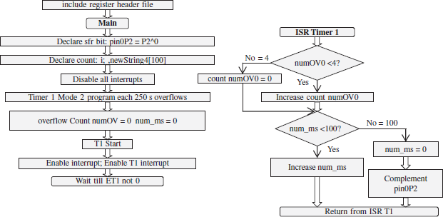
Figure 10.16 Flow Chart of the Program Example of Blinking LED Five Times in 1 s by Pulses of Pulse Interval 200 ms
if (numOV < 4) { /* count T0 overflow from 0 up to 3 */
numOV ++; } else
{numOV = 0;}; /* Count T0 overflows from 0 on next overflow */
if (num_ms < 100) { /* count num_ms, number of ms from 0 up to 99 */
num_ms ++;} else /* Increment num_ms from 0 up to 999. */
{num_ms=0; /* Reset ms and toggle port pin 1 at P2. */
pin1P2 = ~ pin1P2; /* 100 ms over. Therefore, complement pin0P2 output. If ANSC C99 compiler compliant then statement is pin1P2 = ! pin1P2 */
} /* End of interrupt function for timer 0 */}
Millisecond and Seconds Counting Program
Program Example 10.51: Write a C program for an interrupt function timer0ISR. It counts the number of overflow from timer T0 in mode 2. When number of overflows exceeds 4 then increments num_ms (number of milliseconds) and when num_ms exceeds 1000 then increments num_s (numberof seconds). T0 in mode 2 overflows after every 250 μs.
#include <reg51.h> /* Include header file for the registers and SFRs of 8051. */
void main (void)
{
unsigned int numOVTO;
unsigned int numms;
unsigned int nums;
/* Assign initial values 0*/
num_ms=0;
num_s= 0;
EA = 1;
ET0 =1;
. /* Code for specifying T0 in mode 2 and overflow after every 250 μs.*/
.
} /* End of the main */
/*Declare interrupt function for T0 with use of the bank 3 by it.*/
void timer0ISR (void) interrupt 1 using 3 {
if (numOVT0 < 4) { /* count T0 overflow from 0 up to 3 */
numOVT0 ++; } else
{numOVT0 = 0;}; /* Count T0 overflows from 0 on next overflow */
if (num_ms < 1000) { /* count num_ms, number of ms up to 1000 */
num_ms ++;} else /* Increment num_ms from 0 up to 999. */
{num_s++; /* Increment num_s, number of s */
num_ms = 0; /* Count num_ms from 0 from next ms */
} /* End of interrupt function for timer 0 */}
10.16 PROGRAMMING EXAMPLES FOR EXTERNAL DATA
Refer Section 10.2.1. Data types can be declared in the 8051 compiler as follows:
- xdata Memory: Indirectly addressable external RAM memory for data. 8051 has full internal space 64 kB byte of external data memory.
- far Memory: Extended RAM memory spaces after 64 kB. 8051 versions, for example Philips 80C51MX has 8MB far memory. They are pointed by 3-byte address. (It depends on the compiler). It is accessed by user certain defined functions for the specific 8051 versions.
- pdata Memory: It is paged external data memory of 256 bytes. It can be accessed by simple instruction MOVX @R1 or MOVX @R2.
The following examples show the ways of using the external data memory in C.
Program Example 10.52: Write a C program for saving an array of ASCII codes of numbers 0 to 9 in external data memory between RAM address 0 and 255.
#include <reg51.h> /* Include header file for the registers and SFRs of 8051. */
void main (void)
{
unsigned char i; /* Declare Temporary variable i between 0 and 255. */
unsigned char pdata numberCodes [10]; /* Declare an array of ASCII codes of the numbers 0 to 9.
*/
for (i = 0; i<10; i++) {
numberCodes [10] = 48 + i; /* ASCII codes of the numbers 0 to 9 are from 48 to 57. */
. } /* End of the main */
Program Example 10.53: Write a C program for saving an array of a to z 26 ASCII codes of alphabets at external data memory between RAM address 0 and 65535.
#include <reg51.h> /* Include header file for the registers and SFRs of 8051. */
void main (void)
{
unsigned char i; /* Declare Temporary variable i between 0 and 255. */
unsigned char xdata numberCodes [26]; /* Declare an array of ASCII codes of the alphabets a to z. */
for (i = 0; i<26; i++) {
numberCodes [10] = 65 + i; /* ASCII codes of lower case alphabets are 65 to 90 */
. } /* End of the main */
10.17 PROGRAMMING EXAMPLES FOR REAL-TIME CLOCK
Refer Section 6.3. Real-time clock (RTC) is based on interrupts at the regular intervals. This facilitates scheduling of different system tasks at the regular intervals. 8051 does not have RTC device. However, mode 2 can be programmed to get interrupts at the programmed intervals. The following example shows a C-program for regular interrupts after 16 ms in 8051 and calls a function for the actions and updates. Function can be called RTCISR.
Program Example 10.54: Write a C program for running an interrupt service function RTCISR after every 16 ms tick of real-time clock. RTCISR one of the function is to up date the time in rtc variables for the ms, s, m, hr and day from the start of timer T0 in mode 2 in 8051.
There is mode 2 of timer T0, which can be used to call RTCISR after every 16 ms.
#include <reg51.h> /* Include header file for the registers and SFRs of 8051. */
struct {unsigned int rtc_ms; unsigned int num_ms;
unsigned char rtc_s; unsigned char rtc_m;
unsigned char rtc_hr; unsigned int rtc_day;} newtime;
void main (void)
{
unsigned int numOVT0;
/* Assign initial values 0*/
numOVTO = 0; /* Number of overflows = 0.8*/
newtime.num_ms=0; /* Number of ms = 0 */
newtime. rtc_ms = 0; /* rtc time ms = 0 */
newtime. rtc_s= 0; /* rtc time s = 0 */
newtime. rtc_m =0; /* rtc time m =0 */
newtime. rtc_hr = 0; /* rtc time hr = 0 */
newtime.rtc_day =0; /* rtc time day = 0 */
EA = 1;
ET0 =1;
. /* Code for specifying T0 in mode 2 and overflow after every 250 μs.*/
While (1) {
;} /* While loop endlessly for ever. */.
} /* End of the main */
/*Declare interrupt function for T0 with use of the bank 3 by it.*/
void timer0ISR (void) interrupt 1 using 3 {
if (numOVT0 < 4) { /* count T0 overflow from 0 up to 3 */
numOVT0 ++; } else
{numOVT0 = 0; /* Count T0 overflows from 0 on next overflow */
if (newtime.num_ms < 16) { /* count num_ms, number of ms up to 15 */
newtime. num_ms ++;} else /* Increment num_ms from 0 up to 16. */
{newtime.num_ms = 0; /* Count num_ms from 0 from next ms */
RTISR (newtime); /* Call RTCISR */
}}
} /* End of interrupt function for timer 0 */}
void RTCISR (newtime) {
if (newtime. rtc_ms < 1000) { /* count rtc_ms from 0 up to 999 */
newtime. rtc_ms += 16; } else
{ newtime. rtc_ms = 0; newtime.rtc_s ++;}; /* reset rtc_ms and increment rtc_s */
if (rtc_s < 60) { /* count rtc_s from 0 up to 59 */
newtime.rtc_s ++; } else
{ newtime. rtc_s = 0; newtime.rtc_m ++;}; /* reset rtc_s and increment rtc_m */
if (rtc_m < 60) { /* count rtc_m from 0 up to 59 */
newtime.rtc_m ++; } else
{ newtime. rtc_m+ = 0; newtime.rtc_hr ++;}; /* reset rtc_m and increment rtc_hr */
if (rtc_hr < 24) { /* count rtc_hr from 0 up to 24 */
newtime. rtchr ++; } else
{ newtime.rtc_hr = 0; newtime.rtc_day ++;}; /* reset rtc_hr and increment rtc_day */
/* Statements for the actions on RTC 16 ms interrupt */
} /* End of RTCISR after 16 ms*/}
SUMMARY
- A C program consists of a source file having the preprocessor directives having include, define and typedef commands, global declarations and macros, main and other functions.
- A high-level language enables development of a lengthy and complex program in short time. When the appropriate compiler and development tools are available, writing more than 100 or 1000 lines of code is much less time consuming. It uses data structure, functions, structures and decision control blocks. It also facilitates the data-type declarations. It enables the type checking.
- An 8051 compiler allows declaration of memory types. Memory types can be data, xdata, idata, pdata, code, far.
- The operations are done on the constants and variables.
- Variables and data types, arrays structures and unions, pointers, loops and decisions, functions, library functions, in-line assembly, modules and programs are used in C.
- Logical operations are done on Boolean type variables and SFR bits.
- Pointers are used to point to the address of a variable, data structure or function.
- Parameters to a function can be passed by value or by reference.
- GNU tools can be used for programming in C. The SDCC or Keil compilers can be used for programming for 8051.
- Programming examples are given how to write interrupt functions. Interrupt functions are written for the functions, which run on hardware interrupt in 8051. One can define the register bank for the interrupt function.
- The example of C programs are explained for the followings: ports, serial port, timers, external memory, externall pin interrupts and real-time-clock ticks.
KEY TERMS
Array: A data structure in which number of members exists, and each member is accessed by an index number starting from 0 to n - 1, where n is the number of members in the array. A character or integer or float variable or data object can be a member of the array. Array provides ease in handling loops or performing the same set of operations on the members.
Arguements : A collection of paramaeters, which are to be passed to the called function from the calling functions.
Branching: An operation in which a program counter changes from the expected next instruction address location to another location and which changes a sequence of the program flow. Branching is used in a case of the program loops or program decision blocks.
Build process: A process of generating the final binary image of the software. Build process uses a compiler and assembler, linker and locator.
Case statement: A statement with multi-way branching and executing of the statements as per the case defined by value of an expression.
char: One-byte variable for 8-bit operations which is used to save a number between 0 and 255 or ASCII code of the characters or number between −128 and + 127.
Comment field: A field having the comment (not the meaning but the purpose of the statement or code-block), which is ignored by the compiler and assembler but improves the program understandability, readability and which facilitates the program modification process at a later date.
Compiler: It translates the statements in the source file and generates an object file in the program build process.
Control structure: A program-loop or decision block or statement-block, which does the program flow control and branching from the program as per the need or condition in a loop.
Data structure: A data set collection, which is having the special features, like a stack, array, list, table, queue, pipe or tree.
Data type: A named type of data in a program, for example, char data type meaning an ASCII character, int data type meaning an integer.
Data-type definition: A defined data type in a program, for which the programming language does not have in-built specifications. For example, a boolean data type may not have inbuilt definition. Using typedef directive, a data type can be defined in C.
Decision block: A code-block life if … then … else … in a C program. It uses while () {} or if … then … else or case statements.
Development tools: Software utilities like SDK (software Development tool kit), GTK (graphic tools kit), source code engineering tool, sniffer, compiler, assembler, linker, library manager, run-time library, simulator and debugger. These help in easy, fast and reliable software development.
FIFO: A first in first out structure used for a queue or pipe.
float: A four-byte variable, which is used to save a binary word in IEEE 754 format and the word corresponds to a decimal value having sign (+ or −), decimal point, fractional numbers and exponent numbers. Examples are −3.141 or 6.534 × 10⁻⁷.
for: A control structure in which a statement block executes from an initial condition to a last condition in a loop, before the beginning of the loop, the variable, which defines that the condition is continuously incremented or decremented.
Function: A function is a routine, which can be passed the values or pointers through the arguments and which additionally can return a value or data-object or pointer by the function name. C program consists of functions only. A function can also be declared as void functions.
Global variable: A variable, which shares between two or more functions and which is allocated a static memory location, for example, a variable for time and date, which can be used by the display function as well as updating function.
GNU tool: The tool available as FSF (Free Software Files), which is used to create other distributable software for free use by others. [Free means at no cost.]
Hierarchical design: A design in which there is one entry and one exit point and which has branches like a tree from a root. Each routine or code block except the root has a parent. Each daughter originates from a parent. The parent means calling function or object and daughter means called code-block.
If-then-else: A control structure (set of statements) in which a condition test occurs and if condition is present then a statement block executes else another statement block executes.
In-line assembly: Inline codes of assembly languages placed in a high-level language C program.
int: A data type for a integer of two-byte variable in small devices such as 8051 and four byte variable in advanced processors such as ARM. The variable is used to save a binary word for the integer numbers.
Library: A set of standard functions, which are directly called by the functions in the source file. A programmer does not have to write code for that. The library functions can also be dynamically linked or linked at the build process.
LIFO: ‘A last in first out’ structure used for a stack or nested structure.
Local variable: A local variable, which does not share between two or more functions, which is allocated a stack space to begin with and which is de-allocated from the stack space on exit from the function. It is protected from the modification on interrupts or branching call to other code-blocks.
Loop: A code block like while … do …
Macro: A named code-block like a function. It executes on invocation. The compiler replaces the named macro used (in any of the functions or routines) by the codes at the block. The statements of the block are as per ones defined in the preprocessor directives for that macro.
Main: The first function from which a source file program starts.
Memory type: A specification of memory used for a variable. The specification can be for internal memory or data memory or code memory in a program.
Nesting: Nesting means one branch leading from a function to another, the new function code leading to another depending upon the conditions at a statement in it and so on such that the branching and returning backward are in the reverse sequence.
Null pointer: A pointer pointing to nothing (no data or instruction). An unused memory location can be defined as Null pointer in the preprocessor directives. An empty list (list with no elements or items) or queue (queue with no elements or items inserted into it) or a last list-element points to null.
Object file: A file prepared using the source code file by the compiler and assembler. It can be linked to other object files. The linked object file generates final executable file by a locator program.
Page: A memory can be partitioned into contiguous address spaces of equal size and a page corresponds to one of the partition. Page address (page start-base address) is known priory in an instruction. Only offset from this needs to be addressed while addressing the memory.
Page 0: A page corresponds to one of the partition with page address from 0x0000H. Only off-set from page 0 needs to be addressed while addressing the register or memory within the page.
Parameter passing: Assigning the value of a variable or data object from one statement-block (function) to another by sending the reference (pointer address) or by sending the value through the arguments or through a return statement. Parameter(s) passes from a codeblock to the stack on an interrupt or call to another routine and pass back on return from that.
Pointer: A pointer to an address. Let us assume that x is a pointer. Then *x used in an expression or function argument means the value or data-object or function at the address x. [If x is declared as a variable not as pointer, then &x points to the address of x.]
Preprocessor directives: The directives like include, define, typedef, declarations, macro that are present in a program before the main function starts.
preprocessor directives: Just as a program uses the commands, assembler uses the directives, for example, ORG 0 for originating the codes from the address 0. Powerful assemblers provides for the number of directives.
Reentrant function: A function, which reenters in the same state as before its interruption or branching-call when there is return back to it.
Static variable: A variable allocated an address that can be used in distinct functions of a program. Global variables are declared as the static.
Typedef: A directive in C for the data type definition in a program when the programming language does not have in-built specifications for data. For example, a boolean data type may not have inbuilt definition. Using typedef directive, it can be defined in C.
Type checking: A high-level language provides for type checking. For example, it can prevent multiplication operation between two characters. Data type is first checked before the operation on a variable is permitted.
Void function: A function if declared void, then does not return any value through its name.
While: A control structure in which a statement block executes till a condition is true.
REVIEW QUESTIONS
- Describe advantages of programming in high-level language. What are the advantages of programming in C?
- What is ANSI C? What is the meaning of ANSI compliant compiler? What are the additional extensions in C compilers for 8051 versions and derivatives?
- Explain basic programming features of C. What are the preprocessor directives and declarations in C? Describe uses of the modifiers and typedef.
- What are the memory types in a C compiler for 8051?
- What are the data types in a C compiler for 8051? What is the advantage of declaring memory type as well as data type?
- Explain how the parameters of a statement-block in a function pass-by value to the called function.
- Explain how the parameters of a statement-block in a function pass-by reference to the called function.
- Describe the for, while and repeat control structures for the loops.
- Describe how the decision blocks are used using if then else statements.
- Explain the uses of global variables, local variables and constants in a program.
- What are the static variables? Can a static variable assigned in one function be modified by another function? Why does a local variable assigned in one function not modified by another function or interrupt? What is a reentrant function?
- What is the difference between the function and macro in C?
- What are the differences between the data struc- tures—array, struc and union?
- How are the pointers used? A pointer for a float is incremented by 1. What is the change in address?
- Describe uses of source code file, object file and linked objects file.
- Describe the components of a program development tool. When do you use the GNU tools?
- Give features of SDCC.
- Give features of Keil C compiler Cx51.
- How do you use the ports of 8051 in a C program? How do you read the port bits of 8051 in a C program? How do you write the port bits of8051 in a C program?
- How will you write a blink function in C? Assume an LED connected to Port P2 bit0.
PRACTICE EXERCISES
- List the memory types and data types in SDCC compiler latest version for 8051.
- List the memory types and data types in Keil compiler latest version for 8051.
- Write a C Program to write 0x00, 0x55, 0x AA and 0xFF at ports P0, P1, P2 and P3.
- Write a C Program to toggle fourth bit at P2 after every 200 ms.
- Write a program to generate square pulse of 10 kHz at P2 pin 0.
- Write a program to generate two square pulses of 10 kHz at P2 pins 0 and 1 such that they are 180 out of phase with each other.
- Write a program to receive serial input in mode 0 and save the input bytes at the memory addresses between 0x80 and 0xFF in internal data memory.
- Write a program to receive serial input in mode 1 at 2400 baud using timer T1 and Xtal of frequency 24 MHz.
- Write a program to send serial output in mode 0 from addresses between 0x80 and 0xFF in internal data memory.
- Write a program to send serial output in mode 3 from addresses between 0x80 and 0xFF in internal data memory, such that TB8 = 1 when number of 1s are odd in a byte.
- Write a timer function to generate 100 μs delay when using a 12 MHz Xtal.
- Write a timer function to generate 100 ms delay when using a 12 MHz Xtal.
- Write a blink of LED function in C such that blinking period in ms and s can be passed as arguments to that function. Port address is also passed in the argument. [Example blink (P2^0, 10, 1) to toggle the port 2 bit 0 every 1 s 10 ms (= 1010 ms).
- Write an interrupt function for external interrupt0 to find the time interval between first and fourth falling edge and hence the pulse frequency.
- Write a C program for running an interrupt service function RTCISR after every 32 ms tick of realtime clock. RTCISR one of the function is to up date the time in rtc variables for the ms, s, m, hr, day from the start of timer T0 in mode 2 in 8051. RTCISR calls a date function to set the date of the year when day changes.
MULTIPLE CHOICE QUESTIONS
- Pointers in C are needed for pointing to_____.
- a variable or data object like queue, table, array in memory
- an external memory address
- a variable or data object like queue, table, array or function in memory
- a value at a memory address
- Consider Keil C51 compiler.
- Memory saves a generic pointer using two bytes. The pointer specifications are independent of the memory internal or external or specific location. The second byte is the high-order byte of the offset value. The byte 1 is the low-order byte of the offset value.
- The pointer specifications are independent of the memory internal or external or specific location. The first byte specifies the memory type. The second byte is the high-order byte of the offset value. The byte 3 is the low-order byte of the offset value.
- Memory saves a generic pointer in Keil C51 compiler using three bytes. The pointer specifications are dependent of the memory internal or external or specific location. The first byte specifies the data type. The second byte is the high-order byte of the offset value. The byte 3 is the low-order byte of the offset value.
- Memory saves a generic pointer in Keil C51 compiler using three bytes. The pointer specifications are independent of the memory internal or external or specific location. The first byte specifies the memory type. The second byte is data type. The byte 3 is the address.
- A programmer _____.
- should use variables even for the values that remain constant throughout the program for the given case constant values registers
- should use constants wherever possible
- can use either variable or constant
- should use the registers for the constants
- Branching without saving on to the stack or registers is after _____.
- the loop, if then else and case statements
- a call
- the loop, if then else and case statements and interrupts
- return
- bit isGlowing = 0; and static bit isComplete1 = 0; differ in following way: The variable is-Glowingis
- of 1-bit and at address of isGlowing, the value = 0 is assigned at the function; and isCom- pletel is 1-bit address. isCompletel value remains constant in the program.
- at 1-bit address = 0 is assigned at the function; and isComplete1 is of 1-bit and at address of isCompletel, the value = 1 is assigned for use in the functions.
- of 1-bit and at address of isGlowing, the value = 0 is assigned at the function; and isCompletel is 1-bit address.
- of 1-bit and at address of isGlowing, the value = 0 is assigned at the function; and isCompletel is of 1-bit and at address isCompletel is for use in the functions, the value = 1 is assigned in this function.
- Consider statement long *Counts in SDCC or Keil compiler; A pointer Counts, which points to set
- of 2 addresses, which save the 16-bit long integer for the Counts. Pointer saves in the internal data memory of the 8051.
- of 6 addresses, which save the 16-bit long integer for the counts. Pointer saves in the internal data memory of the 8051.
- of 8 addresses, which save the 64-bit long integer for the counts. Pointer saves in the internal data memory of the 8051.
- of 4 addresses, which save the 32-bit long integer for the counts. Pointer saves in the internal data memory of the 8051.
- Comments field comments _____.
- are redundant part of a program just for understanding the program by the learner
- helps in explaining the meanings for better understanding of the program by the learner
- explains the meaning of an instruction or statement
- improves program readability, gives purpose of a program section, and improves program understanding, distinguishes various components of the program and makes modifications and debugging easier
- Macros are _____.
- Good program features are _____.
- structured and modular design
- correct results
- free from bugs
- structured, modular, abstract and heirarchial design
- Structured programming is by the use of _____.
- hierarchy, sequential, repetitive, decision structures
- control structures
- sequential program flow design
- repetitive and decision structures
- A program build process consists of _____.
- using editor
- using compiler, assembler, linker and locator
- using compiler and assembler
- using data type, data structure and control structures like loops and decision blocks
- Parameters pass between two functions by _____.
- stack
- registers
- registers, global variables, pointers, stack and processor status word
- registers, global variables, pointers and stack
- Which of the statements is correct?
- Global (static) variables
- local variables
- global as well local variables in the registers
- pointers save on the stack on interrupt
- Development tools consist of _____.
- program build process tools, and debugging and simulation tools
- compiler and assembler
- editor and assembler
- all the functions and library functions in the program needed for the development
- Preprocessor directives are _____.
- include and define
- include, while and for
- include, if-then-else, for
- for main function in the source file
- TMOD = 0x24 does the following: Assign the timer T1 start-stop external gate pin
- active, timer T1 using internal clock inputs and timer T0 mode = 2, Assign the timer T0 start-stop external gate pin inactive, timer T1 using external clock inputs and timer T0 mode = 0.
- inactive, timer T1 using internal clock inputs and timer T0 mode = 0, Assign the timer T0 start-stop external gate pin inactive, timer T1 using external clock inputs and timer T0 mode = 2.
- inactive, timer T1 using internal clock inputs and timer T0 mode = 2, Assign the timer T0 start-stop external gate pin inactive, timer T1 using external clock inputs and timer T0 mode = 0.
- inactive, timer T1 using internal clock inputs and timer T0 mode = 2, Assign the timer T0 start-stop external gate pin inactive, timer T1 using external clock inputs and timer T0 mode = 4.
- unsigned char pdata numberCodes [10]; for (i = 0; i < 10; i++) { numberCodes [i] = 49 + i; ASCII codes of the numbers 1
- to 9 and : are assigned to numberCodes [0] to numberCodes [9]
- to 10 and : are assigned to numberCodes [0] to numberCodes [9]
- to 9 and : are assigned to numberCodes [1] to numberCodes [10]
- to 10 are assigned to numberCodes [1] to numberCodes [10]
- sfr16 T2 0xCC; T2 is an SFR of 16-bit, the lower byte
- TL2 is at 0xCD and higher byte at 0xCC.
- TL2 is at 0xCC and higher byte at 0xCD.
- = 0xCC and higher byte = 0xCD.
- = 0xCD and higher byte = 0xCC.
- TH1= −3; TMOD = 0x20; TR1 = 1; Then Baud rate = _____.
- 9600 when Xtal frequency = 11.0592 MHz when SMOD = 0.
- 9600 when Xtal frequency = 12 MHz.
- 2400 when Xtal frequency = 12 MHz.
- 9600 when Xtal frequency = 11.0592 MHz when SMOD = 1.
- SBUF = setChar [i]; SBUF register is
- written the byte from setChar [i] = i
- read and character sets at setChar [i].
- is written the byte from setChar [i] and then it transmits through serial port
- read and data saves at setChar [i].
FILL IN THE BLANKS TYPE QUESTIONS
- Unsigned char data PortBytes [20] means PortBytes is _____ and index can takes value from _____ to _____
- n = 20; a = 0; for (i = 0, i < n, i++) {a= a + array 1[i];}; are the statements for _____, array 1[i] with i = _____ to _____
- SDCC (_____ C Compiler) 2.9.4 is _____ source, _____ ANSI-C _____ compliant compiler. SDCC is distributed with all the _____, _____, and files. It is usable with _____/NET. SDCDB is SDCC _____ and ucSim is SDCC _____
- char (_____-bit) for ASCII character, char [ ] an array of characters for a string, byte (_____-bit), float (…-bit), double (_____-bit double precision IEEE _____ standard), unsigned _____ (32-bit),_____ (16-bit), and long (32-bit) in 8051 C compilers.
- _____ x means x is global variable and is initialized in another source-module. It initialized only once and not reinitialized at the entry of the present module.
- memory: It is paged external data memory of 256 bytes. It can be accessed by simple instruction _____ or MOVX @R2.
- sbit portBit = _____; /* declare variable portBit address as the fifth bit address in SFR P1. */ portBit = 1; /* Assign value = 1 at address of portBit */
- 16-bits in TH0-TL0 = 0xB2A8 in mode 1 for delay = 20 ms. Xtal frequency = _____ MHz Xtal in classic 8051.
- xdata counts = 0x10C1B0. It means counts is at _____ and _____ address of counts value = _____. It is of .. bytes and counts address is of …. bytes.
- SM0 =1; /* SCON bit _____ = 0 for mode _____ serial variable baud rate 11 T */SM1= 1; /* SCON bit _____ = 1 for mode _____*/ SM2 = 0; /* SCON bit _____ = 0 for mode _____*/
- Standard C has declaration as follows: <[> _____ <]> functionName (<[> _____ <]>).
- 8051 C has compiler has declaration for interrupt function as follows <[>return_type<]> functionName (<[>_____<]>) <[>{small |_____| large}<]> <[>re-entrant<]> <[>interrupt x<]><[>using y<]>
- _____ means the readily available functions.…… functions are directly used by the programmer. The compiler uses the functions statements from the _____
- The development tools needed are C _____, assembler, linker, library _____, runtime library _____, _____, and debugger. _____ optimizer means peeping into the operation and modifying it into _____ operations.
- A write to the _____ transmits the bits serially. A read from _____ receives the bits serially. _____ controls the transmission and receiving actions at the serial port. It also has the status bits for _____ and RI.
- if (numOVTO < 4) {numOVTO ++;} else {numOVTO = 0;}; if (num_ms < 1000) { num_ms ++;} else {num_ms =0; } means that numOVTO can take the values between _____ and _____ and num_ms can take the value between _____ and _____
- IE = 0x00 means _____ all interrupts, and to enable all 5 interrupts IE = _____
- portByte = 0xAA; /* portByte variable is assigned the value= _____*/ P2 = portByte; means odd pins will be = and even pins = _____
- functAddr = (void *) functName; It means functAddr _____to the _____
- char data *projectName; It means _____ and pointer is of _____ bytes.