
11
Real-time Operating System for System Design
Chapter Outline
- Learn the meanings of task
- Learn the meanings of real-time handling of multiple tasks
- Learn the simplification of system design and using real-time operating system (RTOS)
- Understand the functions in RTOS kernel using an example of RTOS of Keil (RTX51)
- Learn how inter-process communication helps in synchronizing the running of the tasks using signals, semaphores and mailboxes
11.1 REAL-TIME OPERATING SYSTEM
Many systems require several jobs to be performed at the same time. An example is mobile smartphone. A smart phone could be waiting for a call as well one may be entering an SMS message into it. The system timer is also updating the time and date at periodic intervals. The display timer is being reset by pressing some key and the display starts. If there is no action for 15 s, the display-timer time outs and switches off the screen-display.
Real-time operating system (RTOS) is required when the system requires several jobs to be done at the same time and in real-time space. RTOS is used when a complex application consists of multiple tasks, and each task is to be programmed in real-time. RTOS is used when the user tasks have soft or hard real time constraints for the actions. Let us first learn the meaning of several terms before we understand the RTOS.
11.1.1 Multi-tasking System
Task
A task is a set of instructions which are used to perform some action or a set of actions in a system such that the running of the task is controlled by system’s software. Consider two examples of the tasks in two systems. (1) A task switches off the screen lights in a mobile phone system after a certain period of idleness. Other tasks do other actions. (2) A task initiates the sensing of analog signals from the electrodes and performs the analog to digital conversions at successive time intervals. Other tasks do other actions in an ECG recording system. (ECG means electrocardiogram)
A system consists of multiple tasks and the system’s software supervises the running of the tasks. Consider two examples.
Example 11.1
Consider two tasks in an ECG recorder system:
- One task initiates sensing, converts the analog signals into digital and saves the recorded data along with the patient, time and date and other information. The data are saved in memory in an appropriate format.
- The second task retrieves from memory the patient information and displays the ECG on the screen with an appropriate title and label.
Example 11.2
Consider five actions in a digital camera system. An image frame consists of a number of pixels. The pixels are arranged horizontally in rows and vertically in columns. Each horizontal row has additional pixels which are unexposed to light from the image. Four tasks are as follows:
- One action is as follows: A camera click is sensed and system initiates sensing of pixel intensities in the exposed rows of image frame, converts the analog signals for each pixel using an ADC and saves data in temporary memory-buffer M1.
- The action is to sense the pixels in un-exposed rows (dark area rows) near the image frame and analog signals for each dark pixel are converted using the ADC. The data for each row are averaged and average values for each un-exposed row are saved in temporary memory-buffer M2. Then M2 has the offset values for each row.
- The third action is to retrieve the pixel data from each row from M1 and subtract the offset for each row from M2, encode (compress) the off-set corrected image data for all rows in an appropriate format (jpg or gif) and saves the encoded image data along with image, time and date information in image data memory M.
- The fourth action is to retrieves from M the encoded information of image and fifth action is to display the image on the LCD screen along with an appropriate title and label.
Each set of actions can be handled by the system tasks. Each task can execute as seperate process. Five actions are handled by five or four or three tasks by the RTOS.
Multi-tasking System
A multi-tasking system is a system consisting of multiple tasks. Figure 11.1 shows a two-task system. The system software controls the running of the tasks. Apple iPhone, digital camera and ECG recorder are the examples of multi-tasking systems. The system runs the tasks at different times.

Figure 11.1 (a) Two Tasks Running in a System on a CPU at Different Time Intervals, ΔT1 and ΔT2, and (b) A Task i Sending a Signal in the System and a Waiting Task j Receiving the Signal from the System to Start
Consider a two-task system. Let one task start at time t1 and second task start at time t2. Figure 11. 1(a) shows the running of two tasks in a system CPU (or microcontroller) at two different time intervals, ΔT1 and ΔT2. tsw is the task-context switching time interval. (t2 − t1) = ΔT1 + tsw.
Task Context
Context means information of the present program counter, stack pointer and other CPU registers. When context of one task saves and context of new task retrieves then the new task runs. There is time called context-switching time, that is the time spent in saving the context and retrieving the new context. New context runs new task.
11.1.2 Tasks in a Multi-tasking System and Real-time Operating System (RTOS)
Real-time means the time which is continuously incrementing from the system’s start and different actions takes place in the system at different instances of this time. A real-time operating system (RTOS) is an operating system (OS) that has system-software required to synchronize and schedule the tasks in a multitasking system in real-time and takes care of the real-time constraints in the system.
Task States
RTOS controls a task which is controlled to be in one of the following states at any given instance—ready, deleted, running, timeout, waiting for a specific period or waiting till some signal or message before some specific or undefined period. [Ready means RTOS regularly checks that when it gets a signal for which it is waiting or a message for which it is waiting or when there is time out for its waiting-period over.] RTOS can be considered as an operating system which controls the tasks of the states in real-time.
Real-time Constraints
Often, in an application, the multiple tasks are required and the tasks have real-time constraints. Real-time constraint means maximum time latency (wait) before which it should start after an event(s). Real-time constraint also means the time-limit up to which it must respond to an event(s), and time limit within which it must finish. Each task needs to be scheduled to run on the CPU, may need to synchronize the actions and may interchange (send and receive) the signals and messages through the system. The task of higher priority when ready and gets the signal or message for which it was waiting, the RTOS preempts (blocks) the low-priority task. This enables function of that task within the time constraint.
Consider a task for downloading and displaying a video frame during video conferencing. The video-frames are generated every 1/15 s or 1/12.5 s. Video-conferencing is done in real-time. The task must start such that a frame displays every 1/15 s or 1/12.5 s.
Example 11.4
Consider tasks for initiating brake and applying the brake in an automobile system. The task must have latency of 0.1s and must start within 0.1s after signal from brake-initiating task.
Task as a Process or Thread
A task executes like a process or program thread in a multi-tasking system. The task executes under the control of an OS or RTOS. [Process and thread are the terms used in UNIX and Linux. Thread is a term used in Java.]
A task can be called a process because it performs a series of sequential operations to arrive at a result. Process does not branch to another process by calling that process. Process can only send a signal or message to the system and the system passes it to another task.
A task can also be called a program thread because it performs a series of sequential operations and arrives at a result. Use of the term thread is because a thread has no in-between branches that lead to another end point and thus has only one start point and one end point. Thread does not branch to another thread by calling that thread. Thread can only send a signal or message to the system and the system pass it to another thread.
11.1.3 Inter-Process Communication (Inter-Task Message) Functions
Inter-process Communication Using a Signal
Signal is a software interrupt. Signal is communicated when a software interrupt instruction executes. Signal means a call for action on an event after which the system runs a signal-handler task, similar to running of an interrupt service routine on interrupt.
Several times, when one task finishes a certain set of codes only then the system can start another waiting task. The signal can be used for doing this. A signal is sent when that set of codes finishes. The RTOS communicate that to the waiting task and then that task runs.
Example 11.5
Consider two tasks of Example 11.1 for the ECG recorder.
Tasks run at two different times. One task i on finishing a set of actions sends a signal to the system using a signalling instruction. The system passes the signal to the waiting second task j. Then j runs. Figure 11.1(b) shows a task i sending a signal and a waiting task j receiving the signal to start executing.
Consider four actions of Example 11.2 for the digital camera. Assume each set of actions is handled by seperate tasks. Thus there are four tasks.
All tasks run in four different time slots. The first task is executed when the system sends it signal stj, for example, from the interrupt service routine. The routine executes on the user pressing a switch to start taking the picture. The first three tasks must execute in sequence one after another. The second starts when the first task sends signal st2. The third task executes when the second task sends it signal st3. The fourth task executes when the system sends it message md4 to start or the task 3 sends signal st4.
The message md4 specifies which image is to be retrieved from M. The signal st4 initiates task 4. The task 4 then selects the required image and retrieves that for the display.
A signal is the simplest inter-process function (IPC) function. A task can issue a signal to task j that is waiting at some point for that signal (Fig. 11.1(b)). The wait can be for an indefinite period (defined by wait = 0) or for a defined period by the number of ticks of the system clock. After the wait is over or on the signalled event, whichever is earlier, the task will either proceed further or will vector to some other pointed address on timeout.
The signal permits a task run after signalling and notifying RTOS, which lets task or ISR waiting for the signal to run.
Inter-process Communication using Semaphore
Figure 11.2(a) shows a task i sending (releasing) a semaphore (token) s1 at time t1. Then section of codes in waiting task j takes over the resources (CPU, memory, IOs, etc.) and the codes starts executing at time t2. The j then releases s1 at t3 after finishing certain actions and then the blocked (waiting) task i receives s1 to start executing later at t4 in case i is waiting for s1.

Figure 11.2 (a) A Task j Receiving a Semaphore (Token) s1 at t2 so that it Takes Over the Resources, and Later Releases that and the Waiting Task (Task i) Receives the Semaphore s1 to Enable Task i to Run at t4. (b) A Task i Sending a Message and a Waiting Task j Receiving the Message at mailbox M1 to Start Executing at t2
Inter-process Communication Using Message into Mailbox
Figure 11.2(b) shows a task i sending (releasing) a message into a mailbox M1 at time tj. Let the message be a string “Error, network not found.” [String means a set of characters.] A task j waiting for message at M1 and is in blocked state. When M1 receives the message, j receives (takes) the message from the system and when the system blocks i, unblocks j and j runs at time t2.
Inter-process Communication Using Signals and Messages
Consider the following examples.
Example 11.7
Consider a hypothetical example of a toffee vending machine system (TVMS). Figure 11.3(a) shows the four tasks and their priorities. Assume that there are four tasks in the system.
- Task taskkeyparsing parses the action needed from the keys entered by the customer.
- Task taskdsply displays the idle time message(s), the messages during response to customer queries and the customer selection of a specific toffee. The task is also to facilitate the graphic user interactions (GUIs).
- Task taskmoney collects the cost of toffee in terms of coins (or debit card) from a customer.
- Task tasktoffee delivers the selected toffee, whether chocolate or almond or mango-flavoured.
Figure 11.3(b) shows the four tasks in ITMS example and the interaction among the tasks through intertask signals or semaphore or messages.
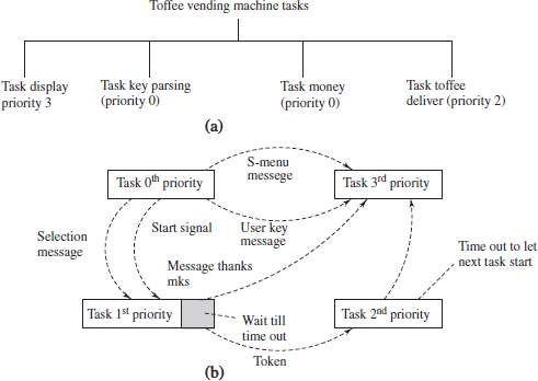
Figure 11.3 (a) Four Tasks in a Toffee Vending Machine System and Their Priorities and (b) Interacting Tasks Through Inter-task Semaphores or Signals or Messages
There are several constraints of time in Example 11.7. For example, taskkeyparsing, taskmoney and tasktoffee should wait for a specific period for the customer input, wait for specific period for coins from customer, should deliver toffee within specified time limit.
The following events occur:
- Inter-task signal to the system from taskmoney that the toffee cost has been collected.
- Inter-task message to the system from taskkeyparsing that which toffee is selected, which the customer selects from the menu.
The taskdsply (i) waits for signals and inter-task messages from taskkeyparsing in order to respond to the customer queries, customer selections, (ii) facilitates the GUIs (graphic-user interfaces), (iii) waits for signal from tasktoffee to have finished the job so that it displays the message for thanks and (iv) starts displaying the idle time messages once again after the specified period.
Example 11.8
Take an example of an application, pick and place robot (Section 8.26). Pick and place robot is robot used for picking something from a position and placing that thing at another position by moving its motors. It works as follows: The robot is first taught by the user from where to pick, how to move and where to put.
It can also be designed by considering it a multi-tasking system. The multiple tasks can be for (i) learning task, (ii) robot running after learning, (iii) sensing the object-proximity, target proximity and position, and taking rotatory and linear encoder data and (iii) multiple motors controls. The RTOS controls which one to run when and which tasks to block (wait) by employing the inter-task signals and messages. Using the RTOS, the scheduling as well as synchronization of tasks is programmed in the robot.
11.1.4 Real-time Operating System
RTOS is a system software for the following main actions:
- Enables division of system programming into multiple tasks that simplify program design.
- Controls the synchronizing and scheduling of tasks like time-critical tasks in real-time.
- Controls the sharing of system CPU, memory, files, devices, network and IO subsystems among the tasks and ISRs.
- Allows optimised scheduling and allocation of system resources (CPU, memory, etc.) to multiple tasks and ISRs.
- Controls the signalling and messaging among the tasks.
- Controls the execution of ISRs and signalling and messaging from the ISRs.
- Provides the interfaces for user interactions (UIs). An interface for UI is a program (routine) for inputs and outputs between the application codes in display task, keypad read task and system hardware.
- Provides the drivers. A driver is a program having functions for using a system device by the application codes. The common functions are for the creation, opening, reading, writing, closing and deleting the device.
- Provides the APIs (application programming interfaces) for developing the codes for system applications.
- Provides a development environment for a multi-tasking program.
RTOS can also be defined as a background program that controls the execution of a number of application sub-tasks and facilitates communication between the subtasks. Here the term, subtask is used to refer to a task of a multi-tasking system.
Tasks can be either for the application or for the system. For example, encoding and compressing image data is an application task and the display device task is a system task.
ISRs can be either for the application or for the system. For example, executing a software interrupt instruction in an application program or interrupt due to keypad input is the ISR for an application. The interrupt device routine on interrupt from a system clock (system timer) is a system ISR.
RTOS is in between a software layer, which is between an inner layer for hardware and top layer for the tasks and interrupt-service routines. Figure 11.4(a) shows layer structure. System software for basic functions is also called kernel. Figure 11.4(b) shows kernel structure.
A commercial RTOS example is RTX51a in both full and tiny versions for 8051 family MCUs [Refer Section 11.2]. RTOS codes can be developed by a programmer. A reader may refer to Michael Barr,b and Myke Predko,c for developing the C/C++ or assembler program as well as RTOS codes. However, for most system design tasks, a commercial or open-source RTOS is preferred.

Figure 11.4 (a) An OS is a Layer Between Hardware, Applications, System Tasks and ISRs. (b) An OS is a Kernel Between Hardware, Applications, System Tasks and ISRs
The system clock generates a timeout at regular (preset) intervals. It is called a clock tick. The tick interrupts the RTOS at regular intervals. System clock ticks are used for real-time actions.
Example 11.9
- The system clock in an RTOS—RTX51 Full can be set between 1000 and 40000 cycles per second. RTX51. The system clock can be set using timer RTX166/167 full version.
- The system clock in Tiny RTOS can be set between 1000 and 65535 cycles per second. The system clock can be set using timer RTX166 tiny version. The timer generates the timer ticks (cyclic interrupts) in RTX51.
Scheduling of running of a task on a CPU
There are different ways of scheduling like cooperative, round robin and preemptive (Section 11.1.5) in the operating systems. There can be preemptive scheduling by the RTOSes. The preemptive scheduling means that low-priority task preempts (blocks) when a high-priority task gets the requisite signal or message.
Example 11.10
- An RTOS example is RTX51 Full version for 8051. It provides for preemptive scheduling. RTX51 full includes RTX166 for timer functions.
- An RTOS example is RTX51 Tiny version for 8051. It provides for cooperative and round robin scheduling. Preemptive scheduling is not available for use in tiny RTOS version.
When a system clock ticks, it initiates RTOS. System clock period is of the order of tens of ms. The RTOS then gathers the information of all task states from the memory blocks called event and task control blocks. RTOS takes the necessary further action. RTOS controls the assignment of CPU and other resources (memory, input-output sub-system, network sub-system, devices and files). RTOS acts as per the available signals, semaphores and messages for the blocked tasks at the instance of system clock interrupt.
11.1.5 Task Characteristics in a Multi-tasking System
The task characteristics and therefore a system design in which an application program divides into multiple tasks should be as per the following guidelines:
- Only one task can run on the microcontroller’s CPU at a given instance.
- A task cannot call another task but it can call the function(s) to implement certain action(s).
- Each task must have a task ID.
- A task can generate signal(s) or semaphore(s) or mutex or message(s), called inter-process communication (IPC) function or inter-task message. This is done on finishing certain section of the codes of task. [Semaphore is also known as a token. Mutex (term derived from mutually exclusive access) is a form of semaphore, which is used for the mutually exclusive accesses of the CPU to a certain set of codes.]
- An IPC is used by another task (s) that may be waiting for that or may need to take a note of that or by a task controlling and scheduling program (RTOS).
- The tasks may be scheduled by cooperative scheduling. The tasks cooperate in an instrumentation system. Cooperating means when one finishes only then does the other start. Figure 11.5(a) shows cooperative scheduling in a measuring instrument system.
Example 11.11
ECG recording system (Example 11.1) or digital thermometer needs the cooperative scheduling by the RTOS. The tasks are scheduled for the key parsing, generation of source signal for sensing, measuring the analog signal from transducer, display, storing and printing.
7. The tasks may be scheduled by round robin scheduling. Round robin scheduling (Fig. 11.5(b) for case of n = 4 equal-priority tasks) is a form of scheduling in which each task 0th or 1st or 2nd or … (n-1) runs for a time slice. After the time slice (timeout after expiry of certain period), task interrupts to switch to the next task and cyclically again starts execution from the 0th task.
Example 11.12
Consider a baby-weighing machine system (BWMS) that is used to record children’s weight and growth. Task 0 a key-parsing task. It is for entering the child identity, age and various other details using GUIs. Task 1 and Task 2 are for sending the appropriate signals to the transducer and measuring the digital data. Task 3 is for the display of ID, weight and graphic presentation of growth on LCD panel, record saving in flash and printing the displayed results after formatting. This system can be designed by four tasks—task 0, task 1, task 2 and task 3: task key parsing, task for current or voltage signal generation for transducer, task for transducer signal measurement and task for display, store and print. RTOS schedules these in the cooperative mode (Fig. 11.5(a)) but the tasks are cyclically repeated or are in the round robin mode (Fig. 11.5(b)).

Figure 11.5 (a) Cooperative Scheduling in a Measuring Instrument System. (b) Round Robin Scheduling of Four Equal Priority Tasks in Baby Weighing Machine
8. A task may be assigned the same priority number as another, when these cooperate to let one finish before another starts or when these run in the round-robin way by assigning the time slice for each task.
9. The scheduling can be preemptive scheduling in case the tasks are assigned different priorities in the system. Each task may have an assigned priority number to give it a priority over another. The scheduling is called preemptive scheduling when a high priority task can preempt another. Preemption means action before other doing action and preventing another in advance. For example, in an TVMS, taskdsply has the lowest priority; other tasks get precedence over it and can preempt it from action. Suppose, there are four tasks 0, 1, 2 and 3, let the priority numbers be defined as 0, 1, 2 and 3. In that case, the task 0 preempts task 1 when 0 is gets the signal or message, task 1 can preempt task 2, task 2 can preempts task 3 and task 3 runs when none of the tasks 0, 1 and 2 can run. Ready means waiting for no timeout or signal or message.
Example 11.13
Give three examples where the preemptive scheduling is required.
- An automobile system needs the preemptive scheduling. Fuel injection control and brake tasks have high priorities compared to display task as they have minimum interrupt latencies.
- Consider that task 0 receives the video-frames from a network in a receiver buffer and puts the byte into a memory buffer. Task 1 separates the data part of the stream data in the memory buffer. Network is sending a stream of bytes. Task 0 for receiving the byte stream will have the highest priority than the task for using the buffer. The streaming bytes should not be missed. The other task can run only for the inter-frame interval in which the receiver buffer is waiting for the bytes. Hence, the control when to suspend and wait is with the kernel functions in RTOS and the higher priority task preempts the low priority task. The preemptive scheduling is used in this case.
- Consider higher priority task in toffee vending system. Why will you use the preemptive scheduling so that both tasks run? The task for receiving the cost of toffee has a higher priority than the task for delivering the toffee. The coins inserted by the customer should not miss being counted. Hence, control when to suspend itself and wait for toffee delivery is with the higher priority task. The preemptive scheduling is used in this case.
10. Each task has a memory block (or register set) allocated to it. The block can be called a task control block (TCB) or task information block (TIB) or process control block (PCB). The block also associates events control block, (ECB) ECB keeps a table of actived or used and inactive signals and messages. The table also keeps information about timeout and waiting timers. Figure 11.6 shows a TCB of a task, which is used to run or block the tasks under control of an RTOS.
11. A TCB saves, for example, the task (i) signal-mask (a single bit for the task, which masks (bit = 1) the running of the task). It means the task cannot run unless the mask is removed (bit = 0) by the OS, (ii) state (present status to specify if it is running or waiting to start again after a timeout set or interval sets, which are the timer values between start and end of a wait when waiting for a message, waiting for a semaphore, waiting for a signal or deleted signals and messages as not needed any further), (iii) sent message or semaphore (which is yet to be acknowledged or responded) or signal (iv) next action pointer (s) (v) priority number, (vi) context, for example, registers including stack pointer and return address pointer (bytes for the program counter that load when it blocks to let another task take CPU or resources control or when it finishes).

11.1.6 Semaphores and Mailboxes
Semaphore as a Token
A task can wait for taking (receiving) a semaphore (by oswait function) at a certain point before proceeding any further. Another task needing the same semaphore at a certain point gets blocked at that point and cannot proceed further till the task that keeps the semaphore pending, releases it (by function os send token) (Fig. 11.2(a)). A semaphore is an IPC (inter-process communication) function, which acts as a token. Token has a property that it is released (given or sent) then it is available (= 1) and when it is taken (consumed or received) it does not become available (= 0).
The wait for semaphore can be for an indefinite period (defined by wait = 0) or for a defined period. The period is defined in terms of number of ticks of the system clock. (number of interrupts of the system-clock) After the wait for semaphore is over or on the semaphore release event, whichever is earlier, the task will either proceed further or will vector to some another pointed address on timeout. Semaphore is used as event flag as follows: Semaphore is used to notify a specific event for which other task section of codes is waiting to occur.
Semaphore in RTX 51
The semaphores can be a maximum of 8 in numbers, of 1 bit each in case of an RTOS, RTX51 (Full version). Semaphores are not available for use in tiny RTOS version.
Semaphore for protecting the modification of a shared variable till the completion of a section of code is used as follows:
Semaphore to Protect Shared Variables or Memory Buffer
Semaphore protects the shared variable modification till the completion of a section of the task by another task section of codes which is also operating on that variable. The section is called critical section. Critical section is a section of codes, which shares the variables or memory before another critical section in other task, and therefore, their running should run mutually exclusive. Either critical section one should run in task one or second should run in task second. Example: Suppose a task n sends data to display buffer, at that instant task m should not send the data to the buffer. When m is sending the data to the display buffer, then n should not. Shared variable means a variable or data object, the operations on which are done at two or several tasks mutually exclusively at a given instance.
Example 11.14
There are four tasks—0, 1, 2 and 3. Consider task 1 having a section of code for updating the timer value, t on a tick or after a specific number of clock ticks. (Refer Program Example 10.50 in Section 10.17) Consider task 2 for setting the time interval by adding x in timer value to set the time interval start time ts and adding timer value y to set the time for time interval end value te. Show the critical section in task 2 and how a semaphore helps in setting the correct time interval by task 2.
Here, t is the shared variable, as it is used in task 1 as well as task 2. Suppose, just after evaluating t + x for time interval start ts, task 2 interrupts. On return from interrupts, the remaining codes will run and t + y time interval and te will be evaluated. Between these two additions, assume that task 1 has updated t because of the clock tick at the timer. Therefore, set time interval will be longer than had t + x and t + y been calculated without interruption, once the set time interval calculations started.
Task 2 is said to be having a critical section, which uses the variable t. Before entering the critical section task 2 can take a semaphore, s. It is a semaphore to run that is set for running task 2. Run is after decrementing s value to 0 and notifying the RTOS before entering the critical section. Task 1 should wait for updating t till s is released by task 2 and s becomes 1. On exiting the critical section, the s is released by incrementing it by 1 and notifying the RTOS. Without use of semaphore, two instructions must be executed as follows: disable interrupt instruction before entering the critical section and enable interrupt instruction on exit the critical section. Disable interrupt will block the timer tick changing the t and will block not only task 1 but also tasks 3 and 4 as well, which are not sharing the value of t. Use of semaphore s between tasks 1 and 2 enables tasks 3 or 4 to run on schedule.
Semaphore can be used as a key for a resource(s) needed by different tasks or sections as follows: Semaphore once taken and for which another task is also waiting, block the waiting task even if it is a high-priority task. That task will unblock on release of semaphore. Semaphore protects the shared variable use in the critical sections. Semaphore in this case is also called mutex semaphore.
Message Passing Using a Mailbox System
A message is expected at a mailbox at a task. A task can get the message (for example, by oswait function) at a certain point before proceeding further. The task cannot proceed further till the task that is expected to send the message, actually sends the message (for example, by os send message function) (Fig. 11.2(b)). The message can be a maximum length of 8 integers in case of RTX51. In the full version of RTOS there can be maximum 8 mailboxes. The wait for message can be for an indefinite period (defined by 0) or for a defined period. The period defines by the number of ticks of the system clock. After the wait for message is over or on the message sending the event, whichever is earlier, the task will either proceed further or will vector to some other pointed address in case of timeout. Mailboxes are not available for use in tiny RTOS version.
Mailbox permits running of succeeding codes in a task run after checking or waiting till getting access to a message sent and notified to RTOS. The RTOS notifies when another task or ISR posts (sends or gives) the message for the mailbox.
11.2 RTOS OF KEIL (RTX51)
RTX51 is multi-tasking RTOS for the 8051 family MCUs. It is from Keil Software Inc.
Installation of RTX51
RTX51 installs by including the files for RTX51 Tiny or RTX 51 Full as follows:
#include <rtxt51tny.h> /* Include the header files for RTX51 Tiny */ or
“#include <rtxt51.h> /* Include the header files for RTX51 Tiny */”
When we use an Integrated Development Environment μVision 2, we select the option Target. Then target the operating system, then RTX51 library file is added by the linker (software). Chapter 12 will describe about the IDE.
11.2.1 RTX51 Functions
RTX51 functions use standard ‘C’ constructs. The functions compiles with the C51 compiler. The C51 compiler is also available from Keil. There are system functions (tasks) and application (user) tasks. There is provision for easily distinguishing them in RTX. Prefix os_ is used for the RTOS functions. There are system and application interrupt service routines.
There is provision to distinguish an ISR also from a task. Prefix isr_ that is used for the RTOS interrupt functions.
Example 11.15
- os_create_task function has the prefix os_ (Section 11.2.4). This is because it is a function of RTOS kernel. It is available in the program when RTOS is included by include preprocessor directive.
- isr_recv_message (k) function has the prefix isr_. It indicates that it is an internal function in the kernel to enable ISR from the task k (Section 11.2.5).
11.2.1.1 Functions for Creating the Tasks
Function os_create_task ( )
Program Example 11.1
Use os_create_task ( ) for creating (activating) four tasks. Schedule them for cooperative round-robin scheduling. Use version, ‘RTX51 Tiny’. Assume that tasks are used in an instrument system.
1. #include <rtxt51tny.h> /* Include the header files for RTX51 Tiny */
.
.
2. job0 ( ) _task_0 {os_create_task (1); /* task 1 created and ready (activated)*/
3. while (1) {
/* Code for task key parsing */
.
.
9. }
10. }
11. job1 ( ) _task_1 {os_create_task (2); /* task 2 created and ready (activated)*/
12. while (1) {
/* Code for task current or voltage signal generation for transducer*/
.
.
19. }
20. }
21. job2 ( ) _task_2 {os_create_task (3); /* task 3 created and ready (activated) */
22. while (1) {
/* Code for task for transducer signal measurement */
.
.
29. }
30. }
31. job3 ( ) _task_3 {os_create_task (4); /* task 4 created and ready (activated) */
32. while (1) {
/* Code for task for display, store and print */
.
.
39. }
40. }
The tasks run as follows:
- When task 0 is executed, it creates (readies) task 1 before an infinite loop at line 3 in the task. Condition while (1) is always true, therefore after the last statement of a while loop the control always returns to the first statement within the while loop.
- When task 1 is executed, it creates (readies) task 2 before an infinite loop at line 12 in the task.
- When task 2 is executed, it creates (readies) task 3 before an infinite loop at line 22 in the task.
- When task 3 is executed, it creates (readies) task 4 before an infinite loop at line 32 in the task.
After the interrupt (not programmed here) of task 4 by the system, RTOS again executes task 0. Cooperative cyclic mode execution means task_0, task_1, task_2, task_3 and again task_0. There has to be some mechanism by which task_i interrupts (blocks) and the control passes in cyclic order to the next task. The next subsections describe this mechanism. (Readies mean get attached with the RTOS so that the kernel function can schedule and also ready to pass signals, semaphores and messages when run and scheduled.)
11.2.1.2 Functions for Blocking a Task so Enable the System to Run Next Task
Exiting the infinite loop in the tasks
We can execute os_wait function at last statement in the loop. The first argument in the function is for timer timeout. It is K_TMO. The OS blocks the running task and passes the control to the next task for a specified period. The use of OS_wait () is explained in Section 11.2.1.3. We can also execute os_wait function with first argument as signal K_SIG in place of K_TM0. OS blocks the running task and passes the control to the next task till other task sends K_SIG signal. The use of K_SIG is explained in Section 11.2.1.4.
11.2.1.3 Function for Synchronizing the Tasks Using Wait Function
Function os_wait ( )
Consider the C statements in Program Example 11.2.
Program Example 11.2
Use os_wait (K_TMO, tn, 0) for task switching between four tasks for round robin scheduling by a version, RTX51 tiny.
Suppose, the system clock is set to tick (on system’s timer-overflow interrupt) at 1 ms, the task loop execution blocks for 10 ms. By executing os_wait (K_TMO, ti, 0) in tasks 0, 1, 2 and 3, where t. is the wait period in terms of number of ticks in the ith task, we get cyclic scheduling between the tasks 0, 1, 2 and 3. K_TMO is message for time out. The timer generates message K_TMO on time-out (timer overflow). The timer programs for system clock ticks = ti. os_wait (K_TMO, 10, 0), when executed as the last statement in the loop will cause exit from infinite loop for a period of 10 timer ticks of system clock.
Figure 11.7 shows the task synchronization by using the following modifications in the codes given in Program Example 11.1. There are just four number modifications at the statements given in that example. Statement number 9,19,29 and 39 are modified.
1. #include <rtx51tiny.h>; #include <rtx166t.h>
/* Let 10 ticks be the cycle time after which a task starts again. That means 10 ms. We can modify line numbers 9, 19, 29 and 39 in Program Example 11.1 to temporarily wait (suspend) each task for 10 ticks, to enable the next series of tasks finish within the 10 ticks.*/
9. os_ wait (K_TMO, 10, 0); }
19. os_ wait (K_TMO, 10, 0); }
29. os_ wait (K_TMO, 10, 0); }
39. os_ wait (K_TMO, 10, 0);}
11.2.1.4 Functions for Synchronizing the Tasks Using Signalling and Wait for Signal Functions
Function os_send_signal (j) and os_wait (K_SIG, 0, 0)
C-statement in RTX51 for the control, os_send_signal (j) does the following actions. It sends a signal, K_SIG to the jth task. The jth task C statement os_wait (K_SIG, 0,0) starts execution immediately as soon as os_send_signal (j) command executes in the previously running task. The RTOS passes the signal from a task on executing os_send_signal (j) to the jth task executing oswait (K_SIG, 0, 0) for the wait of K_SIG.

Figure 11.7 Task Synchronization by Four Modifications in the Statements at the Codes in Program Example 11.1 for the Program Example 11.2
Program Example 11.3
Assume four tasks. Use os_send_signal ( ) and os_wait (K_SIG, 0, 0) for starting the task 0 and then do round-robin scheduling by switching of the tasks by RTX51 Tiny using the functions for signalling. The argument is 0 for number of system clock tick in wait function. It means infinite wait.
Figure 11.8 shows the task synchronization by nine modifications at the statements in Example 11.12.
2. os_send_signal (0); /* Send signal to task 0 */
job0 ( ) _task_0 {os_wait (K_SIG, 0, 0); /* Wait for receiving signal for infinite period */
os_create_task (1); os_send_signal (0)
3. while (1) {os_wait (K_SIG, 0, 0);
.
9. os_send_signal (1);};
12. while (1) {os_wait (K_SIG, 0, 0);
19. os_send_signal (2);}
.
22. while (1) {os_wait (K_SIG, 10, 0);
.
29. os_send_signal (3);}
32. while (1) {os_wait (K_SIG, 10, 0);
.
39. os_send_signal (0);}

Figure 11.8 Task Synchronization in Program Example 11.3 by Nine Modifications at the Statements of Program Example 11.1
11.2.2 Using RTOS Functions for Preemptive Scheduling in RTX51
Suppose, there are four tasks 0, 1, 2 and 3, let the priority numbers be defined as 0, 1, 2 and 3. In that case, the task 0 preempts task 1 when 0 is ready and gets required signal or message, task 1 preempts task 0 when 1 is ready and gets required IPC, task 2 preempts task 3 when 2 is ready and gets required IPC and task 4 runs when none of the tasks 0, 1 and 2 are ready to run.
Since each task code is within an infinite loop, the highest priority task 0 suspends itself for a finite time interval and transfers the control to lower priority task(s) by executing oswait (K_TMO, tn, 0) at some point of task loop where a higher priority task is currently executing (Program Example 11.2). This will let the task of lower priority or priorities task run till the timeout period (= tn ticks of system clock) of the higher priority task.
Alternatively, in place of using os_wait function, a higher priority task can also be blocked at a certain point in the task loop for want of a certain signal or semaphore or message. Consider a higher priority task I. Figure 11.9(a) shows passing of control to lower than task I priority task by the os_wait for a timeout after a certain period or wait for the message or signal.
Consider four tasks. Figure 11.9(b) shows preemptive scheduling and passing of control to lower priority tasks by waiting for a preset period tout or for a signal or semaphore s or message m.
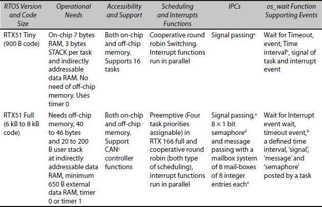
11.2.3 RTX51 Versions
There are two versions of RTX51. (Evalution version can be downloaded from http://www.keil.com/demo/eval. Table 11.1 compares the features in each.

Figure 11.9 (a) Preemptive Scheduling and Passing of Control to the Lower Priority Task. (b) Preemptive Scheduling and Waiting for Signal or Semaphore s or Message m from the Lower Priority Tasks.
- RTX51 Tiny suffices for several applications. It needs to embed into the on-chip memory, though the tasks can access off-chip memories. Table 11.1 gives other operational needs & features.
- RTX51 Full is required for several applications. The system has features as given in Table 11.1. Memory on-chip as well as off-chip are also required.
RTX51 Full has the functions, which enable preemptive scheduling. RTX51 Full has the following features:
- Generates the timer ticks (for cyclic interrupts) using a system timer RTX166/167 full version.
- Provides for preemptive scheduling of a high priority task by switching from a lower priority task.
- It has program codes of = 6–8 Kbytes, data in internal RAM DATA = 40–46 bytes, stack in internal RAM (IDATA) = 20–200 bytes, and external memory XDATA = 650 bytes (minimum).
- It has the many functions compared to RTX51 Tiny. Table 11.1 compares it with Tiny.
Table 11.1 Two Versions: RTX51 Tiny and RTX51 Full Usable by #include <rtx51tny.h> and #include <rtx51full.h>
a C statement ‘os_send_signal (i )’ in a task passes a signal to RTOS to signal K_SIG to /th task when that executes os_wait_signal (K_SIG, 0, 0). Program Example 11.3 explains its use.
b C statement ‘os_wait (K_TMO, 3, 0)’ in a task introduces wait for 3 timer ticks. Timer includes in a preprocessor directive #include <rtx166t.h>. Program Example 11.2 explains its use.
c Controller Area Network Controller is an internal device, for example, in Intel 82256, Philips 82C200 and 80C592.
d Refer Section 11.1.3; Fig. 11.2(a).
e Refer Section 11.1.3; Fig. 11.2(b).
11.2.4 C Functions in RTX51 Tiny
Table 11.2 gives the routines.
Table 11.2 C Functions in RTX51 Tiny

11.2.5 C Functions in RTX51 Full
Table 11.3 gives the C functions in RTX51 Full.
Table 11.3 C Functions in RTX51 Full
| RTOS Function | Description | Purpose |
|---|---|---|
Same as RTX Tiny functionsa |
Refer Table 11.2 |
Refer Table 11.2b |
os_set_slice |
Set the RTX system clock time slice |
Set the period of interrupt from a system clock tick. When the interrupt occurs the OS examines the task states and block or unblock the resources to the tasks |
os_send_token and os_send_ message |
Send a token or message K_SEM or K_MSG to the task i from a task |
To facilitate sending a semaphore or mailbox message to the waiting task i codes so that the task remaining codes can start executing execute.c [Wait is by using os_wait ( ) function] |
isr_send_ message |
Send a message K_MSG to the task i (for from an interrupt) |
To facilitate further execution of the task i remaining codes when there was wait for K_MSG from an ISR |
isr_recv message |
Receive a message K_MSG from an interrupt |
To facilitate further execution of the ISR remaining codes after a message from task i.d |
Disable 8051 hardware interrupts |
To facilitate run of a critical process in a task that must execute uninterrupted. |
|
os_enable_isr |
Enable 8051 hardware interrupts |
To facilitate an interrupt after the critical section codes execution is over in a task |
os_get_block |
Get a block of memory from a pool |
To allocate a block from available memory pool |
os_free_block |
Free the memory block to the memory pool |
To facilitate use of freed block later |
os_check_ pool |
Return information about blocks in the pool of memory |
Knowing about memory block usage |
os_check_tasks |
Return information of all tasks |
Knowing about all the tasks |
os_check_task |
Return information of a task |
Knowing about a task |
os_check_ mailbox |
Return information of a task mailbox |
Mailbox-empty information |
os_check_ mailboxes |
Return information of all task mailboxes |
Mailboxes-empty information |
os_check_semaphores |
Return information of all task semaphores |
Semaphores pending information |
os_check_semaphore |
Return information of a task semaphore |
Semaphore pending information |
os_attach_ interrupt |
Assign a task to an interrupt source |
Execution of the task on an interrupt |
os_detach_ interrupt |
Remove assignment of task to an interrupt source |
Free the execution of the task with an interrupt |
os_reset_mask |
Disable interrupt sources external to RTX51 |
Disable execution of the ISRs for external sources to RTX51 |
os_set_mask |
Enable interrupt sources external to RTX51 |
Enable execution of the ISRs for external sources to RTX51 |
a os_create_task (i), os_create_delete (i), os_send_signal (i), isr_send_signal, os_clear_signal and os_wait (x, tn, 0).
b See Example 11.15, Program Examples — 11.2 and 11.3.
c See Section 11.1.3 for use of semaphore and mailbox.
d For example, interrupting a UART device from a task.
Basic functions which are enabled by an RTOS are as follows—set the periods of system clock tick, disabling and enabling interrupts in the critical process or section of a running task, create (for readying and activating) a task, delete (for idling a task) set time slice for execution of tasks, round robin or preemptive scheduling, task wait by blocking for want of a signal, semaphore (token) or message for indefinite or preset period timeout, sending and receiving (by wait) of signal, semaphore (token) or message, memory block allocation and freeing and task assignment to interrupt source for sending and receiving message.
11.3 USE OF RTOS IN SYSTEM DESIGN
11.3.1 Simple Program Examples for Use of RTX 51 in Design
(a) Use of the Signal Functions of RTOS RTX51
Two LEDs connect to port 1 pins P1.0 and P1.1. A task 0 for port pin 1.0 switches ON the LED for certain number of counts and OFF for remaining period till time out. Timeout is programmable between 1000 and 40000 cycles. Task 1 for port pin 1.1 switches ON the LED for a certain number of counts and OFF for the remaining period till time out.
Program Example 11.4
Use RTX51 tiny for functions for system design of two LEDs ON-OFF program.
1. #include <rtxt51tiny.h>
int counter0;.
int counter1;
2. os_send_signal (0); job0 ( ) _task_ 0 { os_create_task (task 1); /* task 1 ready = 0*/
/* Code for LED at port P1.0 OFF for counts < 10000 and ON for counts <20000 */
while (1) {os_wait_signal (k_SIG, 0, 0);
counter0 =0; P1^0 = 0;
while {counter0 < = 10000} {count0++;};
P1A0 = 1;
while {counter0 < = 20000} {count0++;}; os_send_signal (1);
}
job1 ( ) _task_ 1 {
/* Code for LED at port P1.1 OFF for counts < =10000 and ON for counts <=20000 */
while (1) {os_wait_signal (k_SIG, 0, 0);
counter1 =0; P1^1 = 0;
while { counter1 < = 10000} {count0++;};
P1A0 = 1;
while { counter1 < = 20000} {count0++;}; os_send_singal (0);
}
};
The task 0 and task 1 execute sequentially. Task 1 corperates to let Task 0 finish. When one finish, it sends signal to another. Wait of other end and it starts.
(b) Use of the TimeOut of RTOS RTX166 Tiny Timer in Wait Functions of RTX51 Tiny
Two LEDs connect to port 1 pins P1.0 and P1.1. A task 0 for port pin 1.0 switches OFF for 100 timer ticks and ON for 100 timer ticks. A task 1 for port pin 1.1 switches OFF for 150 timer ticks and ON for 150 timer ticks. RTX51 tiny does an interrupt of each job after a timeout period. The timeout period can be predefined. However, use of the RTOS RTX166 tiny timer and RTX51 Tiny wait functions in a program for this system design is an efficient method. Let us set the timeout for RTX51 tiny system clock for 40000 cycles (maximum limit = 65535).
After system timer ticks, the RTX51 tiny interrupts task 0 and the context switches to task 1. After system timer ticks, the RTX51 tiny interrupts task 1 and the context switches to task 0.
Program Example 11.5
Use RTOS tiny and RTX166 timer for functions for the system design of two LEDs ON-OFF program. Let
1. #include <rtx51full.h>
#include <rtx166t.h>
.
2. job0 ( ) _task_ 0 { os_create_task (task 1); /* task 1 ready = 0*/
/* Code for LED at port P1.0 OFF for 100 ms and ON for 100 ms */
while (1) {
P1^0 = 0;
os_wait (K_TMO, 100, 0); /* Wait for signal K_TMO after the number of system timer ticks (overflow interrupts) increment by 100 */
P1^0 = 1;
os_wait (K_TMO, 100, 0); /* Wait for signal K_TMO after 100 ticks*/
}
job1 ( ) _task_ 1 {
/* Code for LED at port P1.1 OFF for 150 system timer ticks and ON for 150 system timer ticks */ while (1) {
P1^0 = 1;
os_wait (K_TMO, 150, 0);
P1^0 = 0;
os_wait (K_TMO, 150, 0);
}
During the wait for the signal K_TMO in task 0, task 1 is started by the RTOS and vice versa. Signal K_TMO is received after 40000 multiplied by 100 when wait is for 100 timer ticks and system timer ticks are programmed for 40000 cycles.
11.3.2 Case Study of Traffic Light and Use of RTOS in Design
Let us assume a vehicle coming from north. Assume left-lane driving by the vehicles. Left turn (north to west) is allowed directly. Let us assume that there are two set of traffic lights positioned to control north to south (NS for straight path to south) and north to east (NE for right turn) traffic flows. Each set has one green and one red signal.
Even numbered 8051 port 1 pins P1.0 and P1.2 are used for control and to permit the traffic flow along NS and NE by sending green signals NSG and NEG.
ODD numbered 8051 port 1 pins P1.1 and P1.3 are used for control and to prevent the traffic flows along NS and NE and are sent red signals NSR and NER.
Assume multi-tasking using the following tasks:
- Task 0 init: It is the first task to initialize the NS-NE traffic light controller system (NTCS). Assume that task 0 initializes a serial interface program serial. C then creates other application tasks and then deleted. [Deactivated from scheduling by the kernel.]
- Task 1 clock: Controls the time clock.
- Task 2 NSG: Controls the Green ON-OFF along NS using port P1.0.
- Task 3 NSR: Controls the RED ON-OFF along NS using port P1.1.
- Task 4 NEG: Controls the Green ON-OFF along NE using port P1.2.
- Task 5 NER: Controls the RED ON-OFF along NE using port P1.3.
Example: Case Study 11.1
Program for RTOS RTX51functions for system of traffic flows from north to south and north to east using 8051. Each task among 2, 3, 4 and 5 runs for 120000 ms and therefore signal is switched ON for 120000 ms. Assume that RTX166 timer is programmed for timeout after 24000 ms. When ticks = 5 then wait is for 2 m. When ticks = 20 then wait is for 8 m.
#include <rtxt51full.h>
# include <rtx166t.h>
3. void main ( ) { while (1)
{os_start ( ); }
}
4. void init (void) _task_ init {
serial_init.c;
os_create_task (1) /* task 1 ready */
os_create_task (2); /* task 2 ready */
os_create_task (3); /* task 3 ready */
os_create_task (4); /* task 4 ready */
os_create_task (5); /* task 5 ready */
5. while (1) { os_send_signal (2);/* Send signal to task 2*/
os_delete_task (init); /* task_init deleted and RTOS does not take notice of it for ever*/
}
}
6. job2 ( ) _ task_2 {os_wait (K_SIG, 0, 0); /* Wait for signal first from init */
os_send_signal (3); /* Send signal to task 2*/
7. while (1) { os_wait (K_SIG, 0, 0); /* Wait for signal */}
;/* Code for NS light green ON for 120000 ms ( 5 clock timeouts) and then OFF */
8. P1^0 = 1; /* NSG ON */
9. os_wait (K_TMO, 5, 0); /* wait for 2 m */
P1^0 = 0; /* NSG OFF */
10. os_send_signal (3); /* Send signal to task 3*/
};
11. job3 ( ) _ task_3 {
12. while (1) {
/* Code for NS light red ON for 240000 ms (10 clock ticks for timeouts) and then OFF */
13. os_wait (K_SIG, 0, 0); /* Wait for signal from 2 */
P1^1 = 1; /* NSR ON */
14. os_wait (K_TMO, 20, 0); /* wait for 8 m */
P1^1 =0; /* NSR OFF */
15. os_send_signal (4); /* Send signal to task 4*/
11. };
16. job4 ( ) _ task_4 {
while (1) {
/* Code for NE light green ON for 120000 ms (5 clock ticks for timeouts) and then OFF */
os_wait (K_SIG, 0, 0); /* Wait for signal from 3 */
17. P1^2 = 1; /* NEG ON */
18. os_wait (K_TMO, 5, 0); /* wait for 2 m */
19. 1^2 =0; /* NEG OFF */
20. os_send_signal (5); /* Send signal to task 5*/
};
21. job5 ( ) _ task_5 {
while (1) {
/* Code for NE light red ON for 240000 ms (10 clock ticks for timeouts) and then OFF */
22. os_wait (K_SIG, 0, 0); /* Wait for signal from 4 */
23. P1^3 = 1; /* NER ON */
24. os_wait (K_TMO, 20, 0); /* wait for 8 m */
25. P1^3 =0; /* NER OFF */
26. os_send_signal (2); /* Send signal to task 2*/
};
11.3.3 RTOS Functions for Design of Baby Weighing Machine
Figure 1.6 showed a baby weighing machine. Example 11.12 (and Fig. 11.5) showed the round robin scheduling of the tasks in a baby weighing machine system (BWMS) in Section 11.1.5 Example 11.12. We can use a tiny RTOS, which has only OS functions for signals, not for the semaphores and messages. Programming can be done as given in Program Example 11.3.
Figure 11.10 shows the needed RTOS functions in the BWMS using RTOS Full that has the functions for signals, semaphores and messages.
Main function has a start function at a never-ending loop. Once the os_start executes, the program flow is never to this loop. This lets all the four tasks work in round robin.
11.3.4 Case Study of Toffee Vending Machine and Use of RTOS in Design
Figure 11.3 showed four tasks taskdsply, taskkeyparsing, taskmoney and tasktoffee in TVMS and also the interactions among the tasks through signals and messages. Let us take the TVMS to the application of RTOS. Figure 11.11 shows the needed RTOS functions in TVMS using the preemptive scheduling RTOS Full that has the functions for signals, semaphores and messages.
BWMS example in Fig. 11.10 showed that oscreatetask function for creating the next task before the while loop in tasks 0, 1 and 2. So, creation is only once (tasks are readied once here).
Example: Case Study 11.2
Use RTOS functions for system design of TVMS with four tasks for preemptive scheduling by a version, RTX51 Full.

Figure 11.10 Needed RTOS Functions in the Round Robin Scheduled BWMS Using RTOS Full that has the Functions for Signals, Semaphores and Messages
Fig. 11.11 for TVMS example, we have a task named task Start_Application and that creates four tasks in the never ending while-loop but task start Application deletes itself at the loop last statement. After this, the four tasks will only be one in the control of RTOS.
1. #include <rtxt51full.h>
2. void main ( ) { while (1)
{os_start ( ); }
}
_task_ start_Application {
os_create_task (task 0, priority 0); /* task 0 ready and assign priority = 0*/
os_create_task (task 1, priority 1); /* task 1 ready and assign priority = 1*/
os_create_task (task 2, priority 2); /* task 2 ready and assign priority = 2*/
os_create_task (task 3, priority 3); /* task 3 ready and assign priority = 3*/
while (1) {os_delete_task (start_Application); /* task start_Application deleted and RTOS does not take notice of it for ever*/
}
};
3. _task_ 0 {
while (1) {

Figure 11.11 Needed RTOS Functions in TVMS Using the Preemptive-Scheduling-RTOS RTX51 Full that has Functions for Signals, Semaphores and Messages
/* Code for task key parsing */
.
if (select_key) {os_send_message (menu, task 3, 0);};
if (upkey || downkey) {os_send_message (user_Msg, task 3, 0);};
if (enter_key) {os_send_message (slectionMsg, task 2, 0); os_send_signal (task1); };
if (upkey || downkey) {os_send_message (user_Msg, task_3, 0);};
os_wait (K_TMO, task_3, 0);
9. };
10. };
11. _task_ 1 {
12. while (1) {
/* Code for task money*/
coin_collect ( );
if (collect_Money_OK) {os_send_message (Thanks_MSG, task_3, 0); os_send_token (s1); } os_wait (K_TMO, task_2, 0);
19. }
20. }
21. _task_ 2 {
22. while (1) {
/* Code for task toffee delivery */
.
os_wait_message (slectionMSG);
os_wait_token (s1);
os_wait (K_TMO, task_3, 0);
.
29. }
30. }
31. _task_ 3 {
32. while (1) {
/* Code for task for display machine idle state message, menu and cursor as customer user message and thanks message on coin insertion */
.
.
os_check_mailboxes ( ); if (Null) {display (Msg_Idle)} /* call function to display idle machine messages */ os_check_token (s_menu); if (not Null) {display (Menu)} /* call function to display toffee Menu with current cursor */
os_wait_message (user_Msg); if (not Null) {display (user_Msg)} /* call function to display changed menu position from the customer*/
os_wait_message (Thanks_Msg); if (not Null) {display (Thanks_Msg)} /* call function to display thanks message to customer */
.
39. };
40. };
- Taskkeyparsing: When task start_Application executes, the task 0 (taskkeyparsing) is assigned priority 0. Within the never-ending loop when task 0 starts running, there are the following functions—(a) The keyparsing function executes a wait for the customer pressing the keys and parse (find from keys entered) the further action required. (b) Find if the toffee selection key pressed. If yes, ossendtoken smenu function sends a token to display Menu. (c) Find by keyparsing and ossendmessage sends the userMsg. Find if the cursor up key or down key is pressed after the customer sees the menu, if yes and then after parsing os send message sends the userMsg). (d) Find if the selection enter key is pressed (after the customer does correct selection from the menu), if yes then execute os send message selection Msg and os_send_signal (task_1) to let task 1 run for collecting money. (e) If all keys are released, oswait (K_TMO, task_3, 0) function wait period = K_TMO and transfer the control to task_3, taskdsply for K_TMO period. Like Program Example 11.1, this is the way to permit the next highest priority task unblock.
- Taskmoney: When task start_Application executes, task 1 (taskmoney) is assigned priority 1. Within the never-ending loop, when task 1 starts running, there are the following functions—(a) When task 0 signals it to run, coin-collect function executes and task waits for the customer putting in the coins and then a token s1 releases. This is a critical region. (b) If coins value = OK is inserted then ossendmessage sends a thanks message, which task 3 will display later and ossendtoken semaphore s1 is sent to task 2. The function os_wait (K_TMO, task_2, 0) lets the task 2 run for delivering the toffee. Like Program Example 11.1, this is to permit the next highest priority task unblock.
- Tasktoffee: When task start_Application executes, the task 2 (taskmoney) is assigned priority 2. Within the never-ending loop, when task 2 starts running, there are following the functions—(a) Waits for toffee selection message and semaphore s1 from task 1 (b) Delivery function executes for delivering toffee. (c) oswait (K_TMO, task_3, 0) lets the task 3 run for display. Like Program Example 11.1, this is to permit the next highest priority task unblock.
- Taskdsply: When task startApplication executes, the task 3 (taskdsply) is assigned priority 3. Within the never-ending loop, when task 3 starts running there are the following functions—(a) If os_check_mailboxes function returns Null pointers for all the messages, it displays the idle time message(s), MsgIdle. (b) If oschecksemaphore function returns semaphore ‘smenu’ then it displays the Menu. Menu enables selection of toffee (whether almond or mango or chocolate) as per request from task 0 key parsing. (d) The user selects using up and down keys and user_Msg shows whether the user pressed up key or down key. Cursor at the displayed Menu changes the position as per the user message. (e) User inserts the coins, if OK, the thanks message is displayed. (f) Task 3 continues from step (a) when none of higher priority tasks are running.
SUMMARY
- A task is a set of instructions to perform some action or a set of actions in a system such that the running of the task is controlled by system’s software.
- Real-time means the time which is continuously incrementing from the system’s start and different actions takes place in the system at different instances of this time.
- Real-time operating system (RTOS) is required when the system requires several jobs to be done at the same time and in real-time space. RTOS is used when a complex application consists of multiple tasks and each task is to be programmed in real-time.
- RTOS helps in programming the complex, realtime constrained, synchronized and time-critical applications. RTOS can be either self-developed or commercial.
- RTOS is commonly used in the C statements for the following functions:
- set system clock tick periods,
- disabling and enabling the interrupts in critical section at a running task,
- create and delete (for readying and idling) a task,
- set time slice for execution of tasks,
- set round robin or preemptive scheduling,
- task-wait by blocking for want of a signal, semaphore (token) or message for indefinite or preset period timeout,
- sending and receiving signal, semaphore (token) or message,
- memory block allocation and freeing and
- task assignment to an interrupt source for sending and receiving message (s).
KEY TERMS
Cooperative scheduling: A method of running the task in such a way that each one cooperates to let the running one complete.
Context: Registers and variables including stack pointer and return address pointer which must necessarily save on any context switching.
Context switching: Changes of context on interrupt or blocking of the task and running of another task or ISR.
Create : An action to ready a task for running or blocking and synchronizing under the supervision of an OS.
Critical section: A section of a task containing codes modifying some shared variables or performing actions, which are also common to other tasks and in between task switching to another can lead to erroneous results.
Delete: An action to disable a task from the supervision of the OS.
Infinite loop: A set of statements getting executed repeatedly unless blocked in-between because the loop execution condition gets always satisfied.
Interface: A set of codes for implementing or controlling the actions of another set of codes or of hardware.
IPC: An inter-task message or inter-process communication using a signal, semaphore (token) or message (mailbox) and which is sent by a task or process to another waiting task for that so that the waiting task starts running.
Mailbox: A message pointer, which points to a message expected from another task to a task waiting for the message.
Message: A set of integers, bytes, or ASCII codes or a string that is sent from a task to another task using a mailbox and that waits for it.
Multitasking: Division of an application’s program for the application into different tasks such that each task runs as per schedule and synchronization control by the OS (operating system) functions and interfaces.
Mutex: A token to enable mutually exclusive access between the two or more sections of codes or two or more tasks.
OS: A program to enable running of multiple processes (tasks) to control the sharing of system resources like CPU and memory blocks, to control the signalling, and messaging between the processes and interrupts, to provide interfaces between the application codes and system hardware.
Preemptive scheduling: Scheduling of the tasks like a high-priority task when that is (i) ready, (ii) not delayed for a timeout period and gets (iii) a signal or token or message to run then it preempts (blocks) a low-prioroity task.
Real-time: Real-time means the time which is continuously incrementing from the system’s start and different actions takes place in the system at different instances of this time. It is a time that has a fixed and unalterable zero reference and which a system clock advances at constant intervals and which cannot be reloaded.
Real-time constraints: The constraints like a task deadline to finish or a task to start running or a task running latency.
Round robin scheduling: The task runs one after another cyclically and a task cooperates to let the running task finish its loop or its allocated time slice.
RTOS: An OS that takes into account the real-time constraints in addition to the OS specific functions, controls the scheduling of tasks and time-critical tasks and provides an environment for a multi-tasking program.
Scheduling: The order of tasks one after another in time slicing round robin or cooperative or preemptive or other mode.
Semaphore: A token when taken, to let a section or task gets access or exclusive access to run with respect to another section or task until released. There can be different types of semaphores—mutex, binary or counting.
Signal: A signal when sent, to let a section or task get access to run.
Signal mask: A signal when set, to let a section or task get access to run.
System clock: A clock the ticks of which give the timing reference to all the functions of the OS.
System resources: The access of resources like CPU, memory block and devices is controlled by the OS.
Task: A computation unit that readies, deletes, runs, and blocks and which sends and receives signal or token or messages in inter-task communication under the control of the OS functions.
Task control block (TCB): A task information block (TIB) in memory or in a register-set that saves the task state, and includes signal mask, signal, message and semaphore, state, task ID, priority, context which includes the stack pointer and return address of the program counter and other parameters of the task to let the OS schedule its run and control IPCs among the tasks. Each task has seperate TIB.
Task ID: An identification number for each task.
Task priority: When assigned higher priority, gives the ability to preempt another task of lower priority.
Task state: State (running, blocked (wait), readied, deleted), and signal mask.
Task switching: A task first blocking and then let another run after appropriate context saving on the stack and retriving new new-task context from the stack. Context including program counter. The new task then runs.
Task synchronization: Running of the tasks after getting a signal, semaphore or message from a previously running task.
Task wait: Wait for a signal or message or semaphore or timeout period.
Time slice: A time slice allocated to the tasks, after which the cycle starts again.
Thread: A computational unit that has no in between branches that lead to another end point and thus has only one start point and one end point. A thread is minimum schedulable unit. Threads are synchronized thread using the OS functions.
REVIEW QUESTIONS
- What are the advantages of the division of an application into multiple tasks? Define task, task characteristics, task priority and task state. Explain with examples. What are the parameters that must save a task control block? What are the parameters that can be saved at an exemplary task control block?
- (a) Show how a task signals another task waiting for the signal to run. (b) Show how a task sends a semaphore (token) to another task waiting for the semaphore to run. (c) When should you use a signal and when a semaphore?
- Define real-time and real-time operating system. When do you use RTOS for an application development? Explain with examples.
- What is system clock? How does it differ from the clock associated with the microcontroller?
- (a) Explain round robin, round robin time slicing and preemptive scheduling with examples. (b) When do you use each of them? Explain with examples.
- Explain critical section with an example. How do you use a semaphore in critical section of a task?
- When do you prefer to use signal and when semaphore, when notifying to RTOS to let another task unblock? What are the uses of a semaphore?
- Explain mailbox. Show how a task sends message to another task waiting for the message to start. Show how a task sends a message-pointer to another task waiting for that to start.
- Describe the RTOS functions in RTX51 Tiny. What are the program and data RAM needs of the tiny? List the RTOS functions not available in RTX51 Tiny but available in RTX51 Full.
- Explain the meaning of task creation, deletion, waiting for signal, waiting for semaphore, waiting for message and sending signal in RTX51.
PRACTICE EXERCISES
- A multi-tasking system receives an encrypted byte stream of 64 characters maximum with first 16 bytes for the system address, saves decrypted messages in memory. From it four strings are sorted (each string terminating with 00H) and displayed on a four-line LCD display unit, the inputs are checked every 15 seconds. List the tasks, which the RTOS will schedule and show the use of the RTOS functions in the system design.
- A multi-tasking system sends a message of 100 bits every minute at UART port (1 start + 8 data + 1 stop) at 1200 baud to a remote system, which returns an identical message after a gap of 32 ms if the remote system is OK. List the tasks, which the RTOS will schedule and show how to use the RTOS functions in the system design.
- A robot has three motors in three degree of movements. Each motor is having an angle encoder. Each motor receives an input from three tasks. The fourth task measures the position of each motor and sends three directions to the motors to rotate by a, b and c degrees. The a, b and c messages are sent by the fifth task. List the tasks, which the RTOS will schedule and show how to use the RTOS functions in the system design.
- A task does the calibration of a transducer, when it senses a user input key at an instrument and uses old calibration data if the key is not sensed. Let a and b (between 1 and 255) be two calibration parameters. The second task measures temperature T using the input from a transducer every minute and the third task shows it on display after using calibration. Calibration formula is actually T = a . T + b. List the tasks that the RTOS will schedule and show how to use the RTOS functions in the system design.
MULTIPLE CHOICE QUESTIONS
- Real-time means _____.
- actual time
- time from start of a task
- a time that has a fixed and unalterable zero reference, which a clock advances at constant intervals and which cannot be reloaded
- time measured using the system clock of a real-time operating system
- Real-time operating system is one, which
- allows flexible scheduling of the system resources (CPU, memory, etc.) to several tasks
- controls the task synchronization using signals, semaphores and messages
- is an OS for the microcontrollers
- is an OS with preemptive scheduling
- Which of the following options is true?
- A task cannot call any other function
- A function can call a task
- A task can call multiple tasks in a multi-tasking system
- A task can be assigned to an ISR
- Which of the following options is true?
- A deleted task means a task not present in the RAM
- A deleted task means a task detached from the RTOS control and a deleted task cannot becreated again
- A deleted task means a task detached from RTOS control
- A deleted task means a task detached from RTOS control and the deleted task can be created again in the same task or from another task
- A task control block _____.
- saves all the tasks ID, state, priority number, stack pointer, message pointer(s), requested action pointer(s) and return address
- can save the created task ID, state, priority number and return address
- is for RTOS multi-tasking control
- is assigned to a task where the task ID, state, priority number, stack pointer, message pointer(s), requested action pointer(s) and return address save
- Which of the following options is not right?
- A signal is a boolean notification
- A signal and a semaphore are of one bit each
- A signal and a mutex are of one bit each
- A signal, a semaphore and a message are of one bit each
- Which of the following options is right?
- A signal is to notify to the RTOS to permit running of a waiting task or section of a task
- A signal permits running of a waiting task or a section of task
- A signal means start a waiting task immediately on priority
- A signal is from a task that it has finished its task
- Which of the following options is right?
- A timeout is used to let a waiting task or a section of task run after waiting for a signal
- A timeout is used to let a waiting task or a section of task run after waiting for a signal or message or semaphore or timer timeout
- A timeout is a signal not received within the defined number of ticks
- A timeout is a signal or semaphore or mailbox message not received within the defined number of ticks or a wait period over for a blocked task
- Which of the following options is right?
- A task is a program in infinite loop under the RTOS control
- A task is a program thread that has no in-between branches, which lead to another end point and thus has only one start point and one end point and task program can be in infinite loop
- A task is a program that also has an infinite loop and starts only on a signal or action from OS
- A high-priority task must have an infinite loop
FILL IN THE BLANKS TYPE QUESTIONS
- A system consists of _____ and the system’s software supervises the running of the tasks.
- _____ means information of the present program counter, stack pointer and other CPU registers. When the context of one task _____ and the context of other task _____ then that task runs.
- RTOS controls a task which can be in one of the following states at any given instance _____, _____, _____, _____, waiting for a specific period, and waiting till some signal or message before some specific or undefined period.
- Real-time means _____ from the system’s start and different actions takes place in the system at different instances of this time.
- Real-time constraint means _____ before which a task should start after an event(s). Real-time constraint also means _____ the up to which it must respond to an event(s), and time limit within which it must finish.
- Real-time operating system (RTOS) is _____ when the system requires _____ to be done at the _____ and in _____ space. RTOS is in between software layer between _____ and _____ and, routines.
- _____ controls the running of the tasks and interrupt-service routines using the hardware.
- The task of _____ when ready, preempts (blocks) the low-priority task in order to function within the time constraints.
- Task in _____ state of ready when it gets a signal for which it is waiting or gets a message for which it is waiting or time out when its waiting-period is over.
- _____ are assigned to the tasks in preemptive scheduling.
- When the tasks run in cyclic schedule and when one completes then other is signalled to start, then scheduling is called _____.
- The _____ generates a timeout at regular (preset) intervals. It is called _____ The _____ interrupts the RTOS at _____. System clock ticks are used for the _____ actions.
- A task _____ another task but it can call the function(s) to implement certain action(s).
- A task i waits for _____ when os_wait function executes for a period = _____.
- A task i _____ a signal at time t1. Then waiting task j takes the _____ and takes over the resources (CPU, memory, IOs, etc.) and starts at time t2.
- A task i _____ a semaphore (token) s1 at time t1. Then waiting task j takes the _____ and takes over the resources (CPU, memory, IOs, etc.) and starts at time t2.
- A task i _____ a _____ into mailbox M1 at time t1. Then waiting task j the _____ the message and takes over the resources (CPU, memory, IOs, etc.) and starts at time t2.
- A high priority task must be waiting for _____, _____, _____, or _____ so that the lower priority task can run in preemptive scheduling.
- RTX51 Tiny kernel requires only _____ bytes of program memory codes space. When we don’t need _____, _____, and _____ functions we use it. Maximum number of defined tasks can be _____. Maximum number of tasks which can be active are _____ at an instant. It requires maximum DATA space of _____. Bytes in Internal RAM. It requires STACK space of bytes per task.
- RTX51 Full has the functions for preemptive scheduling. RTX51 Full has the following features:
- Generates the timer ticks (for cyclic interrupts) using ______.
- Provides for ______ of a high priority task by switching from a lower priority task.
- It has program codes of = ______ Kbytes, data in internal RAM DATA = ______ bytes, stack in internal RAM (IDATA) = ______ bytes, and external memory XDATA = ______ bytes (minimum).
- It has the functions to enable preemptive scheduling.