
16
Motorola MC68HC11/12 Family
Chapter Outline
- Learn a distinct architecture from 8051 that is present in 68HC11/12 family MCUs
- Understand addressing modes, instructions and memory map in 68HC11/12
- Study powerful features of 10s, SPI, SCI and timers and their applications
16.1 ARCHITECTURE
16.1.1 CPU Registers and Internal Buses
Figure 16.1 shows nine CPU registers, PCL, PCH, IYL, IYH, IXL, IXH, ACCA, ACCB and CCR and internal buses in 68HC11. The architecture has features are as follows:
- 68HC11 is an 8-bit microcontroller. MCU is designed using HCMOS (highspeed complementary MOSFET) technology. Clock frequency can be reduced to 0 since MCU is completely MOSFET-based. The power dissipation is negligible in the state of stop or wait. Stop or wait state can be enforced by an instruction in CPU. The state of run revokes on an interrupt or reset.
- The clock (oscillator) and reset circuits are the external circuits in the MCU. Reset circuit connects to MCU at RESET pin. XTAL of 8-MHz connects to MCU. 8 MHz Oscillator gives clock cycle frequency of 2 MHz. The clock cycle is of 8-MHz ÷ 4 = 2 MHz. It is used for the timing and clock operations of the MCU.
- Common internal bus consists of address bits A0−A7 and data D0−D7. External bus has multiplexed lower 8 address bits and 8 data bits.
- Nine CPU registers are A-B (D), IX and IY, CCR, SP and PC. There are in addition the control and status registers, internal RAM, ROM/EPROM/EEPROM/FLASH and EEPROM.
- Two external interrupts (one definable as non-maskable) are given through IRQ and XIRQ pins. There are two interrupts at the control pins, IRQ and XIRQ. XIRQ interrupt can be made a nonmaskable interrupt within 64-clock cycles. IRQ pin is also used to give Vpp (programming pulse). This is when internal EEPROM is used.

Nine CPU Registers:
- 16-bit program-counter (PC). The PC loads a new value on power-up. That value fetches from reset-vector address, FFFEH (higher)- FFFFH (lower).
- 16-bit Stack pointer, S. (SPL and SPH—two bytes, at odd and even addresses. S must be predefined as there is no start-up default value. S decreases by 1 after the push of each byte and the lower byte pushes first. PUSHY means push IY. First IYL will be pushed at memory pointed by S, the S decrements by 1 and then IYH pushes and S further decrements by 1.)
- Two 8-bit accumulators (called ACCA and ACCB)—can be used as 16-bit accumulator (ACCD) also.
- Two 16 bit index registers, IX and IY.
- Condition code register CCR for flags for the processor status. System control registers and circuits
Other Features
- CONFIG, INIT and other system control registers are the registers that must be programmed (written) in the first 64-clock cycles.
- There are the ALU registers Temp 1, Temp 2 and circuits for test and condition-based branch logic.
- IR, ID and control and sequencing circuits form control unit.
- Internal CPU has the control and sequencing logic with signals.
- The IR (instruction register) are ID (instruction decoder) are used for processing of the instructions.
- Control and sequencer circuit control all the operations at CPU, bus and internal circuit.
ALU
- Arithmetic and logic unit (ALU) does arithmetic and logic operations using the accumulator. One input at ALU is a source operand taken from ACCA (8-bit) or ACCB (8-bit) or ACCD (16- bit). Another input is from another register (or memory). The result of operations by the ALU also returns back to the first source operand ACCA or ACCB or ACCD. Thus, an instruction specifies just one address. Other source address and destination are implied and is ACCA or ACCB or ACCD.
- ALU has the subunits for 8 × 8 integer multiply, 16 ÷ 16 integer divide and 16 ÷ 16 fractional divide (multiply by 10000H then perform 32-bit by 16-bit division).
16.1.2 Ports
Figure 16.2 shows the ports and internal devices along with the CPU registers, internal buses and signals in the internal architecture. Other than CPU registers, there are registers that have memory-like addresses. The ports are as follows:
- There are five Ports A, B, C, D and E. The ports are also used for the signals of a number of devices, timer, serial, multi-channel ADC, PACNT (pulse accumulator counter) and other devices.
- Ports C and D use the data direction registers DDRC and DDRD, respectively. This enables the control of each port bit as either input or output [Fig. 2.6(b)].
- Two ports—Port B and Port C— are also used to access the external memory in the expanded mode of MCU. Port B and Port C multiplex the A0−A15 and D0−D7.
Table 16.1 gives the meanings of symbols and signals used in the block diagram.
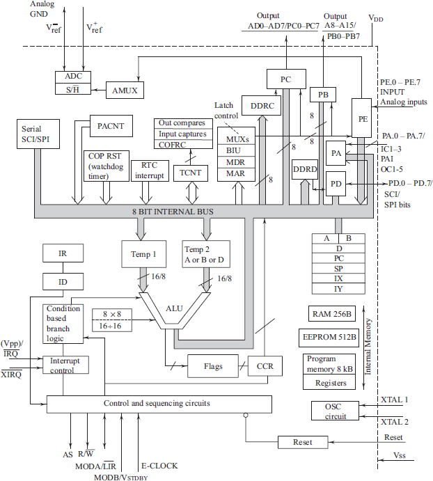
Figure 16.2 Internal Devices Along with the Ports, CPU Registers, Internal Buses and Signals in the Internal Architecture of Version 68HC11A8
Table 16.1 The Meaning and Uses of the Signals and Structural Units Shown in Block Diagram
| Symbol | Full Form | Use |
|---|---|---|
ALU |
Arithmetic Logic Unit |
Performs register arithmetic or logic unit operation. The operands are in Temp1 from accumulator and from Temp2 taken from a register or memory at an instance. The operations are according to the instruction executed |
PC |
Program Counter |
16-bit register PC, holds the program-memory address of the instruction being currently fetched; increments continuously to point to the next instruction, unless there is change in the program flow path. |
MAR |
Memory Address Register |
Buffers an address from the PCL and PCH or Internal Bus. It is for placing address for memory on the External Bus |
PCL |
Program Counter Lower |
Program Counter Lower Byte Register |
PCH |
Program Counter Higher |
Program Counter Higher Byte Register |
Bus Buffer A0-A7 |
Buffer A0-A7 in MAR for external bus |
For Placing A0-A7 at Port C pins when AS = 1 |
Bus Buffer DO-07 |
Buffer D0-D7 in MDR for or from external bus |
For Read or write by accessing the D0-D7 at Port C pins when AS = 0 and either R/ |
Bus Buffer A8-A15 |
Buffering in MAR A8-A15 from PCH or internal bus for external bus |
For Placing A8-A15 at Port B pins when AS = 1 |
MDR |
Memory Data Register |
Buffers to and from data at the Internal and External Buses |
MUX and BIU |
Multiplexer and Bus Interface Unit, botha controlled by controller and Sequencer circuit |
Multiplexes for PC, AD0-AD7 (D0-D7 Data and A0-A7) and A0-A15 Address [AS, R/ |
IR |
Instruction Register |
Holds the current instruction opcode from the four byte queue |
ID |
Instruction Decoder |
Decodes the opcode bits at IR and activates the appropriate signals for controller and sequential circuits |
CCR |
Condition Code Register |
8-bit processor status-register, reflecting status bits, they are used for the test of condition in later instructionb |
Condition Test Branch Logic 8 × 8/16 ÷ 16 |
Condition Test and Branch Logic 8-bit multiply and 16-bit divide |
Circuit to test the flags and initiate an appropriate path for program flow by branching from the continuous flow path 8 × 8 integer multiply, 16 ÷ 16 integer divide and 16 ÷ 16 fractional divide |
S (SPL-SPH) |
16-bit Stack |
Stack is for 16-bit push or pop at internal stack of a program in memory, S is 16-bit stack pointer, for that (SPL and SPH are its part) |
AS |
Address Valid |
Active ‘1’ when CPU is sending an external address on the bus through the ports B and C |
R/ |
Read/ |
‘1’ when reading byte from external memory and ‘0’ when writing byte to external memory |
|
At edge input at reset pin, Mode-A and Mode-B pair = 11 which means expanded mode; = 01 means normal single chip; = 10 means special test; and = 00 means special bootstrap modesd |
|
MODB/VSTBY |
Pin for Mode B and standly V |
Mode-B and also to give Standby voltage V to chip |
a Enables use of external memory addresses to external ROM in place of the ones inside. Used during development phase of the codes for the internal program-cum-data memory. If PC exceeds the value for an on-chip address, then external memory is used irrespective of mode bits.
b CCR saves the flag bits Z, N, V, HC, C, processor external interrupt mask bit and S (stop bit).
c The pin has ![]() active ‘0’ at each E cycle of an instruction after the saving of Mode B bit at HPRIO at the reset- edge.
active ‘0’ at each E cycle of an instruction after the saving of Mode B bit at HPRIO at the reset- edge.
d Mode-A and Mode-B are the bits and they save at reset edge. Save as SMOD (b6) and MDA (b5) bits in the HPRIO (High Priority Interrupt) register.
16.1.3 Internal Devices
68HC11 has the control, data and status registers. The registers associate the timer, SPI, SCI, ADC, ports and CPU registers. Figure 16.2 shows the internal devices along with ports, CPU registers, internal buses and signals.
68HC11 has internal devices; Five ports A to E, one 16-bit free-running counter (pre-scalable by four values), one real-time clock (pre-scalable by four values for periods), interrupt handler unit, baud-rate selector, SPI (serial peripheral interface) and SCI (serial communication interface). SPI is serial synchronous communication device. SCI is (serial asynchronous UART device). PACNT, multi channel ADC, 5 Out compares, COFRC and 3-input capture units and computer operating properly (watchdog) timer are other devices. Baud rate selector is a register, which is programmed to select the baud rate for the SCI.
Watchdog timer in 68HC11 is called COP (computer operating properly watchdog timer). SPI and SCI devices are full duplex. Full duplex communication means transmission and reception can occur at the same instances on two distinct lines or channels. They have seperate pins.
Free-running counter, TCNT is pre-scalable by four values for clock-input periods. It can provide five out-compare outputs and three input captures. One comparison can also force the five out-compare outputs.(COFRC)There is subunit for real-time periodic interrupts pre-scalable by four values for periods. (Section 6.2)
Table 16.2 gives the meanings of the symbols used in the figure 16.2 and the uses of the various architectural blocks and devices which are present in 68HC11 family MCU version 68HC11A8.
16.1.4 Memory Addresses
Program counter starts from fetch of two bytes for the address of bootup program. The bytes are taken from reset vector addresses at FFFEH−FFFFH. CPU of 68HC11A8 processes instructions using Princeton architecture for memory. [Same address space for program and data.] There are thus contiguous 64 kB addresses for the on chip, 192 Byte internal RAM (called register file), external RAM, interrupt vectors, reset and COP vectors and Internal 8 kB ROM and remaining internal/external RAM/ROM.
CPU supports higher bytes at lower address and lower bytes at higher addresses. This is called big endian mode of data alignment [Bigger byte first].
Table 16.2 The Blocks and the Meaning of the Symbols Used in the Architecture Overview
| Symbol | Full Form | Use |
|---|---|---|
PA |
Port PA |
Port A has alternate use also for three inputs for captures of TCNT counts and five outputs on five comparisons with TCNT counts. |
PB |
Port PB |
Two 8-bit ports for the IOs in single chip mode (Ports B and C) are multiplexed with address and data bus signals. [Refer Fig. 16.2, Section 16.1.] PB is 8-bit port for the IOs in single chip mode. PB can also be used as hand-shaking port [Fig. 2.6(c)]. PIOC bits control that. |
PC |
Port C with DDRC |
An 8-bit port for the IOs in single chip mode. Port C multiplexes with the AD0AD7 signals. Port C can also be used as handshaking port [Fig. 2.7(e)]. PIOC bits control that. |
PD |
Port D with DDRD |
Port for the IOs in single chip mode. Port D multiplexes with the Serial Port SPI and SCI unit signals. |
PE |
Input Port E (also analog inputs) |
An 8-bit port for inputs at Port PE. It multiplexes the multichannel analog inputs to internal S/H (Sample and Hold) and ADC (Analog to Digital Converter) circuit. |
PACNT |
Pulse Accumulator Counter |
PACNT counts the pulses. |
TCNT |
Free running CounterTimer |
There are the 16-bit internal timing devices, using TCNT (free- running counter timer). a |
RTI |
Real Time Interrupts |
The real time interrupts can be programmed for one of the four-periods. |
SPI |
Serial Peripheral Interface |
Synchronous duplex communication in master- slave mode. This enables multi processor synchronous communication using master’s clock to the slaves. |
SCI |
Serial Communication Interface |
Asynchronous duplex UART communication. It has receiver wake up feature. This enables multiprocessor UART communication. |
On Chip registers |
IO function registers at 32 byte space |
Serial, Timer and IO control and status registers. (Table 16.4) |
Internal RAM |
Internal random access memory of 192 byte |
Used for the read and write at 192 B-memory |
EEPROM |
EE Read Only Memory |
512 B EEPROM |
ROM |
Read Only Memory |
8 kB Masked ROM, EPROM or flash EEPROM or RAM internal or external (controlled by EA signal and internal on chip memory availability). Connects to MAR for the external access and PC for internal access of 16-bits address. |
XTAL1 and XTAL2 |
Pins to the crystal |
Pins to the crystal in the oscillator circuit (usually 8 MHz in 68HC11A8) |
|
Reset pin (Active = 0) |
Reset circuit input and also output to the external peripheral devices. This lets the processor reset synchronize with the devices reset. |
External Interrupt Pins (Active = 0) |
Two external interrupts (maskable) and one of it can be configured as non maskable external interrupt like NMI in 8086 or 80196. |
|
VDD and VSS (GND) |
Voltage supply pin and grounds |
Used for 5 V supply and ground connections, respectively |
Analog GND |
Analog GND as well as V−ref |
Common pins for analog grounds of analog inputs and of reference voltage. |
V+ref |
V+ref, positive voltage reference |
Reference input referring to the maximum analog input for scaling the analog input that is for conversion by ADC outpute.b |
a Devices are three timer value captures when inputs occur at IC1-IC2-IC3 (Section 6.2) pins. When the input is activated, the time value x captures from the counts = x in free- running counter at specific instances. There are five out compare outputs. These give outputs at specific instances after comparisons at five instances of x with the endlessly running TCNT. TCNT count bits = x defines time instance.
b Kept at about 1 or 2 V Scaling means signal conditioning of analog input so that its variations are within the GND and V+ref.
16.1.5 On-Chip Registers (RAM) at 256-byte Address Space 256 Bytes
CPU registers [PC, SP, IX, IY, ACCB-ACCA (also called ACCD)] are separate and are not at the addressable memory space between 0000H and FFFFH. There are common contiguous address spaces between 0000H and FFFFH for the other registers (for ports and internal devices), internal RAM and ROM and external memory. Between x’000H and x’03FH, there are on-chip registers and between x’ 040H and x’ 0FFH is an internal RAM of 192 bytes. The x’ is defined by bits at the INIT register.
x and x’ are the set of four bits each that are used for memory mapping. Mapping is essentially a change of the base for a memory or register block. It is a way in which a memory block is specified.
Figure 16.3 shows the ON-chip RAM map.
Example 16.1
Internal RAM memory allocated to some memory space specified by another baseaddress space or on chip registers allocated to some memory space which is specified by another baseaddress. Registers of 68HC11 when mapped to memory space at 0000H will have addresses beginning from 0000H and when mapped to 1000H will have addresses beginning from 1000H. Similarly, internal RAM space can be mapped to an address block.
16.1.6 On-Chip Program and EEPROM
On-chip program codes start from y000H. The y is defined by bits at the INIT register. On-chip EEPROM is from B600H to B7FFH in case of MCU version of EEPROM = 512 byte. CPU registers are separate and not in the memory-like addressable space.
16.1.7 64 Byte Space for internal-device Function Registers
There are 64B internal-device function registers. Table 16.3 gives the set of symbols, addresses and uses of the registers at on-chip 39-byte RAM space. These registers are ports and timer data and control registers.
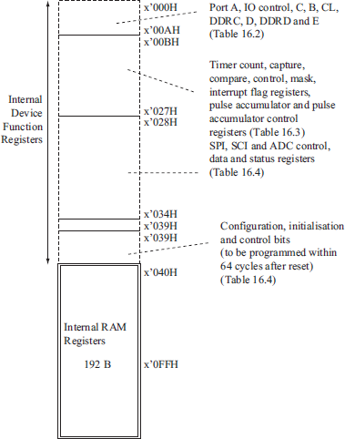
Table 16.3 Ports and Timer Data and Control Registers at On Chip RAM Space
| Symbol | Full Form | Address Mapped to x’000Ha |
|---|---|---|
PortA |
Port A when read or write |
0000H |
— |
Reserved |
0001H |
PIOC |
Parallel IO Control when read or write |
0002H |
PortC |
Port C when read or write. [Associate with DDRC.] |
0003H |
PortB |
Output Port B when write |
0004H |
Port CL |
Port C latched byte when write |
0005H |
— |
Reserved |
0006H |
DDRC |
Data Direction Register bits for Port C (I or O bits) when write |
0007H |
Port D when read or write. [Associates DDRD.] |
0008H |
|
DDRD |
Data Direction Register bits for Port D (I or O bits) when write |
0009H |
PE |
Input Port E when read |
000AH |
CFORC |
Compare and Force output Register (Refer Section 16.5.4) |
000BH |
OC1M |
OC1 action Mask Register (upper 5 bits) when write |
000CH |
OC1D |
OC1 action Mask Data Register (upper 5 bits) when write |
000DH |
TCNT |
Timer Count Register Timer -16-bit Register (when read) |
000E-000Fb |
TIC1 |
Time Input-Capture Register 1 of 16-bit (when read) |
0010-0011b |
TIC2 |
Time Input-Capture Register 2 of 16-bit (when read) |
0012-0013b |
TIC3 |
Time Input-Capture Register 3 of 16-bit (when read) |
0014-0015b |
TOC1 |
Time Out-Compare Register 1 of 16-bit (when read or write) |
0016-0017b |
TOC2 |
Time Out-Compare Register 2 of 16-bit (when read or write) |
0018-0019b |
TOC3 |
Time Out-Compare Register 3 of 16-bit (when read or write) |
001A-001Bb |
TOC4 |
Time Out-Compare Register 4 of 16-bit (when read or write) |
001C-001Db |
TOC5 |
Time Out-Compare Register 5 of 16-bit (when read or write) |
001E-001Fb |
TCTL1 |
Timer Control Register 1 (when write) |
0020H |
TCTL2 |
Timer Control Register 2 (when write) |
0021H |
TMSK1 |
Timer Mask Register 1 (when write) |
0022H |
TFLG1 |
Timer Interrupt Flag Register 1 (when read) |
0023H |
TMSK2 |
Timer Mask Register 2 (when write)c |
0024H |
TFLG2 |
Timer Interrupt Flag Register 2 (when read) |
0025H |
PACTL |
Pulse Accumulator Control Register (when write) |
0026 |
PACNT |
Pulse Accumulator Count Register (when read or write) |
0027 |
a With x’ programmed as 0 at INIT Register, otherwise x’ four bits will be considerd in addresses in column3.
b Higher and lower bytes, respectively.
c TMSK2 has 8-bits Timer overflow mask bit, (TOI), real-time interrupts mask bit (RTII), pulse accumulator input edge interrupt mask bit (PAII). Pulse accumulator overflow interrupt mask (PAOVI) and PR0 and PR1 (TCNT prescaling factor programming) bits.
Table 16.4 gives a set of the symbols, addresses and uses of the registers at on-chip 14-byte RAM space. These registers are used in the SPI, SCI, ADC devices and have bits for the control, data and status. All addresses are 16-bit addresses in 68HC11. Addresses between 000H and 00FFH can be accessed by a direct address of 8-bits in the instructions. The 16-bit addresses are mapped in the tables to x’000H with x’ programmed as 0 at INIT register for 8-bit direct address accessibility.
Table 16.4 SPI, SCI, ADC Control, Data and Status Registers at On Chip RAM Space
| Symbol | Full Form | Address Mapped to x’000Ha |
|---|---|---|
SPCR |
SPI Control bits Register when write |
0028H |
SPSR |
SPI Status bits Register when read |
0029H |
SPDR |
SPI Data Byte Register when read or write |
002AH |
BAUD |
SCI Baud rate control bits Register when write |
002BH |
SCCR1 |
SCI Control bits Register 1 when write |
002CH |
SCCR2 |
SCI Control bits Register 2 when write |
002DH |
SCSR |
SCI Status bits Register when read |
002EH |
SCIRDR |
SCI Receive Data Byte Register when read |
002FH |
SCITDR |
SPI Transmit Data Byte Register when write |
002FHb |
ADCTL |
ADC Control Register when write |
0030H |
AD Status |
AD status register when read |
0030Hc |
ADR1 |
ADC Register 1 (Result for Channel 1) when read |
0031H |
ADR2 |
ADC Register 2 (Result for Channel 1) when read |
0032H |
ADR3 |
ADC Register 3 (Result for Channel 3) when read |
0033H |
ADR4 |
ADC Register 4 (Result for Channel 4) when read |
0034H |
a With x’ programmed as 0 at INIT Register, otherwise x’ bits will be upper 4 bits in the addresses at column3.
b Same address as at above row.
c AD status is also read from same address when read.
Table 16.5 gives another set of the symbols, addresses and uses of the registers at on-chip 7-byte RAM space. These registers are for system configuration, initialization, and control bits. These must be defined within 64-clock cycles after the CPU resets on power-up. These bits are programmed using appropriate instructions for write at their addresses.
Table 16.5 System Configuration, Initialization and Control Bits Written Within 64 Clock Cycles After CPU Resets
| Symbol | Full Form | Address Mapped to x’000H” |
|---|---|---|
OPTION |
System configuration options |
0039H |
COPRST |
Computer Operating Properly SET and RESET COP (watchdog timer) (when written) |
003AH |
EEPROM programming control register (when written) |
003BH |
|
HPRIO |
Highest priority bit, I bit and SMOD and RBOOT bits, etc. Within 64 clock cycles after CPU resets |
003CH |
INIT |
Initialization registers mapping 4 bits and RAM Mapping 4 bits written within 64 clock cycles after CPU resets |
003DH |
TEST1 |
Test control register bits |
003EH |
CONFIG |
Configuration register to enable EEPROM, COP (COP watchdog timer), ROM EEON, ROMON, NOCOP and NOSEC bits written within 64 clock cycles after a CPU reset |
003FH |
a x’ is assumed 0 in column3, else upper 4 bits of address will be as per x’.
16.1.8 Addressable Register Space of 192 B Internal RAM
Between x’040H and x’0FFH there are 192 bytes of on-chip RAM. Those addresses that are not needed for stack can be used as the assumed registers or memory word is of 16 bits and a double word is of 32- bits. A sixteen-bit SP points to the stack.
- A register or memory address is of 16 bits.
- Registers can also be addressed by a direct address of 8 bits. The direct address indicates offset value on the 256-byte page. The page is mapped for the register by four bits x’ at INIT= 0000. Memory can also be addressed similarly.
- There are (i) 39 B of space for the ports data and timer-control registers, (ii) 14 B SPI, SCI and AD control, status and data registers and (iii) 7 B system control and configuration registers.
- Internal 192 B RAM space x’ is programmable by INIT register 4 bits.
16.1.9 Internal RAM
Between x000H and xyFFH there can be RAM. The x (for RAM) and xy (for registers described) may be distinct bits. The bits depend on the additional provision if available for internal RAM at chip. When y = 0 and x = x’ it means that only the 192 bytes internal RAM at addressable registers space is used. (Note: x, x’ and y are of 4-bits each.)
There may be additional RAM outside 256 B (outside 64 B registers space and 192 B internal RAM at register addressable space). The RAM address page location is programmable by INIT register 4 bits.
16.1.10 Memory Map
Figure 16.4 shows full memory map (addresses/address ranges) in 68HC11A8 (8 kB on chip ROM) version for 64 kB contiguous address space. Note that no address space overlaps in 68HC11. The figure shows external program/data memory (PROM/RAM) Space, On-chip Registers and RAM, on-chip ROM/PROM On-chip EEPROM.
Reset, COP Reset and Interrupt Vectors The addresses for the ISRs for 68HC11 internal devices are saved during programming for the device ISRs start up addresses at the interrupt vectors. The vectors are at the addresses between FEC0H and FFFBH. COP reset vector is at FFFC−FFFDH. Power-up reset vector is at FFFE−FFFFH. These two vector addresses can point to same or distinct addresses in 68HC11 MCU.
16.2 ADDRESSING MODES AND INSTRUCTIONS
16.2.1 Addressing Modes in the Instruction Set
1. Inherent addressing:
Example 16.2
Let us consider the instruction, STOP. The stop bit at CCR sets, it stops the internal clock and reduces power dissipation to negligible. Processor is in an idle state. As soon as the reset activates or XIRQ interrupt or any other non-maskable interrupt occurs the STOP state is revoked by restart of clock. The CCR stop flag also resets.
Example 16.3
INX increases IX 16 bit register by 1. CPU registers addressing instructions are also the inherent addressing instructions. XGDX is a one byte-instruction with register IX specified with a few bits in opcode. It exchanges bytes (lower as well as higher) in IX with the ACCD, PSHX is a one-byte instruction with register IX. It pushes the IX onto stack (S, stack pointer decreases by 1 after the push of each byte and the lower byte is pushed first).
2. Extended addressing: The source is specified by an extended 16-bit address.
Example 16.4
1040H will increment byte at 1040H.
3. Direct addressing: The source is specified by 8-bit direct address (lower byte of memory address). Upper byte of address is assumed to be 0x00 or 0xx’0.
Example 16.5
LDD 40H loads higher byte B in ACCD from 40H and lower byte A in ACCD from 41H. If direct address is used for registers then the 4 bits for register mapping defined at INIT register must be reset to 0000. If direct address is used for internal RAM then the 4 bits for RAM mapping defined at INIT register must be reset to 0000.

Example 16.6
BSET (source operand) (mask) is a three-byte instruction. Source operand is 8-bit direct address. It sets bit(s) in memory by logical OR operations. The multiple bits are set as specified at the mask 8-bits.
BSET 20H, 88H will set only b7 and b4 = 1 and 1. This is because only b7 and b4 at mask byte 88H are 1 and 1.
4. Immediate addressing: A byte(s) is at the address that follows immediate operand in the instruction.
Example 16.7
ADD #%00010001. Add a register bits 0b00010001.
ADD #44H will add A with 44H. A will be A + 0b01000100.
ADDD # 44 will add D with 0044 decimal. D will be D + 0d002C.
5. Indexed (indirect) addressing: A byte is at an address pointed by indirect address (also called base address) in IX or IY or IX or IY with an offset.
Example 16.8
Offset is an unsigned 8-bit value specified. Consider instruction SBCA X. Subtract A register with carry and bits at address pointed by IX.
ADDD 10, X adds ACCD register with word at memory address pointed by IX+10. (Higher byte is at IX+10 and lower byte at IX +11).
ADDD 10H, X adds ACCD register with word at memory address pointed by IX + 0x0010. (Higher byte is at IX+16 and lower byte at IX +17).
Some instructions have different ways of addressing while some have only one way. For example, in direct or extended (option) addressing the instructions’ source is specified by either an extended 16-bit address or 8-bit direct address.
Example 16.9
LDD 40H will load a higher byte B in ACCD from 40H and a lower byte A in ACCD from 41H. Direct address uses a nibble (4 bits) defined at INIT register.
LDD 2040H will load a higher byte B in ACCD from 2040H and lower byte A in ACCD from 2041H.
BSET has only one way of addressing (only direct not extended addressing).
INC has one way of addressing like BSET. LDD can use immediate and indexed addressing modes also. BSET and INC can use indexed addressing modes also.
16.2.2 Instructions
Register/memory addresses are contiguous in 68HC11. CPU registers (ACCA, ACCB or pair as ACCD) are dedicated specifically for arithmetic and logic operations and there are indirect address pointers, IX and IY.
(1) Data-transfer Instructions A byte is transferred to a byte address (register) or word address (or register) in a data-transfer instruction or a word is transferred to a word address (or register) in a data-transfer instruction.
XGDX and XGDY are for swapping between ACCD and IX and ACCD and IY (both lower and higher bytes are mutually swapped usually for logical operations using ACCD and later swapped again). CCR does not affect.
PSHX, PSHY, PULX and PULY are for push and pop of words at IX, IY. The TSX and TSY transfer from the addresses pointed by S + 1 into IX and IY. [S increments by 1 before pop of a byte.] CCR does not affect.
TPA, PSHA, PSHB, PULA, PULB transfer from S + 1 pointed address, push and pop A or B using S. CCR flags affect at N (= 0 or 1), Z (=0 or 1) and V = 0 in the following data-transfer instruction: LDD, LDX, LDY, LDS STD, STX, STY and STS STD, STX, STY and STS instructions for load and store ACCD, IX, IY and S. Load and store use five addressing modes described above.
TAB and TBA is the byte transfer between A and B. TAP is byte transfer from A to CCR.
(2) Data and Bit-manipulation Instructions Direct and indexed addressing modes are used. N and Z flags affect in these instructions. V resets.
- CLRA and CLRB load 0x00 into ACCA and ACCB. CLI and SEI clear or set I bit at CCR to disable or enable maskable interrupts handling. CLC, SEC, CLV or SEV clears or sets C or V bit (inherent addressing).
- BSET and BCLR are instructions for setting and resetting the bits by logical OR and AND operation, respectively.
- Instructions exist for the following operations on port-address bits or ACCA or ACCB or ACCD: complement, logical or arithmetic shift left or right, rotate left or right.
(3) Arithmetic Instructions Arithmetic instructions operate on the word operands or byte operands. The first source-cum-operand is ACC (ACCA or ACCB or ACCD) and the second operand source is through addressing modes—direct, immediate, extended and indexed. Arithmetic instructions are add, add with carry, negate, subtract, subtract with C (as a borrow flag), complement, multiply unsigned numbers, divide unsigned numbers and divide fractional numbers. The following are the arithmetic instructions:
- INCA, INCB, INX, INY, DECA, DECB, DECX, DECY increment or decrement A or B or IX or IY. The INC and DEC increment or decrement using the extended or indexed addressing mode (affects N, Z and V).
- ABA, ABX and ABY add the B to A or IX or IY (affects H, N, Z, V and C).
- ADDD, ADDA (affects H) and ADDB (affects H) add ACCD or ACCA or ACCB into a word or byte after using one of the five addressing modes. ADCA (affects H) and ADCB (affects H) add after adding a previously C.
- DAA adjusts the BCD digits into decimals after the addition (affects N, Z, C).
- NEGA and NEGB two’s complement A or B (affects all four N, Z, V, C.)
- SUBD, SUBA and SUBB subtract ACCD or ACCA or ACCB. SBCA and SBCB subtract with the C as well as operand from the ACCA or ACCB (affects all N, Z, V and C).
- MUL multiplies 8-bit unsigned ACCA with ACCB. Result is at ACCD (affects C).
- IDIV and FDIV integer or fractional division with ACCD in the numerator and IX or IY in perform denominator. Result is in the ACC and index register. (Quotient is in ACC) FDIV does a multiplication of ACCD by 10000H and then performs a 32-bit ÷ 16-bit IDIV. (Division affects all four N, C. V = 0 in DIV.)
(4) Logic Operations Instructions The first source-cum-destined operand is at the ACC. Second operand source is taken by use of the direct, immediate, extended, and indexed addressing modes. Instructions affect the CCR flags at N (= 0 or 1), Z (= 0 or 1) and V (= 0). There are the following logic operation instructions:
ORAA, ORAB, ANDA, ANDB, EORA and EORB do logical OR, AND and XOR of second source into ACCA or ACCB.
(5) Comparison and Test Instructions Comparison is performed by hypothetical subtraction. Only the N, Z, and V affect in the instructions for test. The instructions are as follows:
- CBA compares ACCA and ACCB. Results are in C , N , Z and V.
- CMPA and CMPB are for a comparison of ACCA or ACCB. That is with the second source operand from direct, extended, immediate and indexed-addressing mode. Results are in C, N, Z and V.
- CPD, CPX, and CPY are for a comparison of ACCD, IX, and IY with second source operand, which is by direct, extended, immediate and indexed-addressing mode. Results are in C, N, Z and V.
- TSTA and TSTB compare ACCA or ACCB and 00H. C and V = 0, N =1 if b7 = 1 else 0, Z = 1 if b7 to b0 = 0 Z = else Z = 0.
- BITA and BITB tests by hypothetical bit-wise AND operation of ACCA or ACCB with the second source operand from direct, extended, immediate, and indexed-addressing mode. Results are in N, Z and also V = 0.
(6) Program Flow Control Instructions There are four types of program flow control instructions for jump and branch (no flag affects at the CCR).
- Interrupt-related Instructions: (a) STOP instruction executes by setting a STOP bit in CCR and the clock stops and PC remains unchanged till a reset or XIRQ (un-masked) or non- maskable interrupt reactivates the processor, starts clock cycles and resets STOP bit. (b) WAI instruction executes by waiting for an interrupt after pushing nine bytes in the following order—PCL, PCH, IYL, IYH, IXL, IXH, ACCA, ACCB and CCR, PC becomes PC + 1 when the wait ends. It executes a halt instruction. Power dissipation reduces and only the clocking of timers and A/D control registers continues. Any not masked or unmaskable interrupt reactivates Internal clocking. All internal circuits starts and the wait ends. A return from interrupt-related ISR will pop the 9 bytes back into the registers in the reverse order of push. (c) SWI is software interrupt if I =1 in CCR then ISR vector address is taken from FFF6H−FFF7H after pushing 9 bytes for registers. SWI is like the trap instruction at 80196. It is useful for debugging the program at its various stages. (d) TEST instruction repeatedly increments PC till the reset occurs. It is the legal instruction in a processor running in the test mode only.
- Unconditional Jump Instructions: This is an unconditional branch to an address (called jump and symbol is JMP) to a destination extended or indexed address.
- Unconditional Branch Instructions: BRA and BRN are unconditional branches to an address relative to PC. Program branch is to PC+ Rel, PC +1, and PC +2. Rel is specified at the instruction and is a +ve or −ve number between −128 and +127 (a two complement 8-bit number). NOP, BRN and NOP followed by another NOP delays by 2-, 3- and 4-clock cycles, respectively. Clock cycle period is 2 for 8 MHz XTAL.
- Conditional Branch Instructions: Instructions for conditional branch to an address relative to PC are as follows: (a) BRSET is for branch to PC relative if complement of all bits from the memory address ANDs with the mask bits and results in all bits = 0s. (b) BRCLR is for branch to PC relative if all bits from the memory address ANDs with the mask bits and gives all bits = 0s. (c) Two-byte instructions for branch relative if flag(s) condition(s) defined in an instruction exists. BCS, BEQ, BMI, and BVS condition test flags for carry (set), equal, minus, and V (set). BCC, BNE, BPL and BVC test carry (clear), not equal, plus, and V (clear). After CBA, CMPA, CMPB, CMPD, CPX, CPY, SBA, SUBA, SUBB, SUBD instructions the following conditional-branch instructions can execute: BLT, BLE, BEQ, BGT, BNE, BGE, BLO, BLS, BHS and BHI.
Three types of program flow control are as follows:
- Unconditional Routine Call Instructions: JSR is to call to a subroutine at an address defined by an extended or indexed address.
- Unconditional Routine Call at Relative Address Instructions: BSR means branch to a subroutine to a PC value (at the last part of the instruction) obtained after an add with Rel. Then, a branch can either be branch forward or backward.
- Return from Routine Instruction: RTS is return from subroutine. Then the PC pops the saved address at stack top.
- Return from Interrupt Service Routine Instruction: RTI is for return from an ISR. All 9 bytes retrieve back to the CPU registers that were saved on ISR call.
16.3 INTERFACING METHODS
16.3.1 General-purpose Parallel Port IO Interface
Single-chip mode has Port A to Port E. Their alternate uses in the extended mode are as follows:
IO Port A Table 16.6 gives the uses of PA (address 0000H when registers space maps to 0000H) bits. PA provides the interface for inputs or outputs when the internal devices are used for the following: (i) input captures (three number), (ii) out compares (five numbers) and (iii) pulse accumulator. I means input, O means output bit that can be reset or set using BCLR 00H mask or BSET 00H mask instruction if register space starts from 0000H. IO’ means that default function is (i) input at IO pin when reading PA input when using pulse accumulator device or (ii) output when writing and then the pulse accumulator device not used. IO’ direction as output is controlled by setting b7 of PACTL at address 0x26 or when programmable timer is enabled for an OC1 output. IO’ direction as input is controlled by resetting b7 of PACTL.
Output Port B Table 16.7 gives the uses of Port B (address 0x0004 when registers’ space maps to 0000H) when a byte is sent in output (single-chip mode) or for the address signals (expanded mode). O’ means an output byte that can be written using ACCA or ACCB and instruction STAA 04H or STAB 04H when Port B is directly addressable because of mapping of register space to 0000H or because of using extended address x’ 004H or indexed address using IX or IY. STRB output control pin activates to 0 when Port B is used as output so that an external device can latch the output of Port B when STRB = 0. The same output control pin can function as R/![]() pin in expanded mode.
pin in expanded mode.

a When bit not used for an internal device (input capture or out compare or pulse accumulator).
Table 16.7 Port B Output Byte or Address Bus Signals
| Pins | Pins Use as Port Bita | Pins Used as Address Signals in Expanded Modeb |
|---|---|---|
PB.0-PB.7 |
O |
A8−A15 |
a R/![]() pin now is STRB pin.
pin now is STRB pin.
b Processor read data when R/![]() pin is reset (= 1) and write when R/
pin is reset (= 1) and write when R/![]() pin is set (= 0).
pin is set (= 0).
Port C Table 16.8 gives the uses of bits at Port C (address 0003H when registers space map to 0000H). Port C input/output bits use DDRC at 0007H. DDRC can be written as bit = 0 using BCLR 09H mask to use a Port C bit as input. DDRC can be written a bit = 1 using BSET 07H mask to use a Port C bit as output.
DDRC can be written by STAA 07H or STAB 07H instruction. BCLR or BSET or STAA or STAB does not use direct address 07H in case the registers do not map to 0000H but use extended address or indexed address x’007H.
Consider 8255. Figure 7.8(a) showed handshaked signals ![]() and IBF at PC2 and PC1 Figure 7.8(b) showed the handshake for output port operations using two handshaking signals at PC2 and PC1 when using Port B. Similar handshaking signals are used when using Port C in single-chip handshaking port mode in 68HC11. PIOC at 0002H is written when using the handshake mode. STAA and STAB pins are used for Port C handshake signals (Fig. 2.8 (c)). STAA input control pin activates to 0 when PC is used as input so that an external device can send the input to PC when STAA = 0. The same inputcontrol pin functions alternatively. It becomes R/
and IBF at PC2 and PC1 Figure 7.8(b) showed the handshake for output port operations using two handshaking signals at PC2 and PC1 when using Port B. Similar handshaking signals are used when using Port C in single-chip handshaking port mode in 68HC11. PIOC at 0002H is written when using the handshake mode. STAA and STAB pins are used for Port C handshake signals (Fig. 2.8 (c)). STAA input control pin activates to 0 when PC is used as input so that an external device can send the input to PC when STAA = 0. The same inputcontrol pin functions alternatively. It becomes R/![]() pin in expanded mode for data input/output at the processor when 1 or 0, respectively, are activated. Memory device or external peripheral device uses it for sending or receiving data. STAB is output control pin. It activates on setting to 0. Port C is then used for output.
pin in expanded mode for data input/output at the processor when 1 or 0, respectively, are activated. Memory device or external peripheral device uses it for sending or receiving data. STAB is output control pin. It activates on setting to 0. Port C is then used for output.
Table 16.8 Port C Input/output Bits [Address 0003H when Registers Space Map to 0000H] using DDRC at 0007H or Address Cum Data Bus Signals

a Single-chip mode use for an input or output bit. PC.x is as per written DDRC.x bit. AS output pin now functions as input strobe pin STAA. Input at PC does not latch if this pin does not activate in handshaking mode of the port.
b Uses the PIOC written controlling bits for Port C. Handshaking pin signals STAA and STAB used by external IO device.
c Expanded mode—processor sends address bits and sets AS = 1.
d Expanded mode—processor reads data when R/![]() pin set = 1 and writes when R/
pin set = 1 and writes when R/![]() pin set = 1 and makes AS = 0.
pin set = 1 and makes AS = 0.
Port CL (address 0005H) is used with Port C. When using Port C for the handshaking mode input, The ISR executes on Port C interrupt. Port CL is read by an ISR instruction at ISR. Handshaking is by using PIOC read and write. Port C is then read by another instruction.
Port D Table 16.9 gives the uses ofbits of Port D (address 0008H when registers space map to 0000H). Port D six input/output bits use DDRD which is written a bit at 0009H. DDRD can be written a bit = 0 using BCLR 09H, mask to use a Port D bit as input. DDRD can be written a bit = 1 using BSET 09 mask to use a port C bit as output. DDRD can be written by STAA 09H or STAB 09H instruction. BCLR or BSET or STAA or STAB does not use direct address 09H in case registers do not map to 0000H but use extended address or indexed address x’009H.
Fig. 2.14 showed UART serial output and input. Figure 3.17 showed 8051 TxD and RxD signals. There are alternate uses of PD.0 and PD.1 when SCI internal device of 68HC11 is activated for UART mode communication. Pin PD.0 functions as RxD when DDRD.0 is reset. Pin PD.0 functions as TxD when DDRD.1 is set.
There are alternate uses of PD.2 to PD.5 when SPI internal device of 68HC11 is activated for synchronous communication. Pin PD.2 to PD.5 function as MISO, MOSI, SCK and SS. (Table 16.9). DDRD.2 to DDRD.5 must be set or reset as per use of a 68HC11 as master or slave device.
Input Port E Table 16.10 lists the uses of bits of Port E (address 000AH when registers space maps to0000H). Port E is also used for inputs AN0 to AN3 when interfacing a four-channel multiplexed ADC. It is used for AN0 to AN7 when 8 channel ADC is used.
Table 16.9 Port D Input/output 6 Bits [Address 0008H When Registers Space Map to 0000H] Using DDRD at 0009H or Signals of SCI and SPI Serial Port Devices
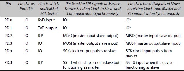
a IO means single- chip mode use for an input or output bit. PD.x is as per DDRD.x bit written (0 or 1). This mode is when pins are not used by internal serial devices SCI and SPI.
b When pin is not used for SCI.
c When pin is not used for SP.
- There are five ports in single chip mode, Port A to Port E.
- Port A pins can also be used by input captures, out compares and pulse accumulator devices.
- Ports B and C can be used for address and data buses in the expanded mode.
- Port C can also be used in handshaking mode input or output port.
- Port D is also used for SCI and SPI.
- Port E is also used for inputs from analog channels.
Table 16.10 Port E Input 8 Bits [Address 000AH when Registers Space Map to 0000H] or Analog Signal from Analog Input Channels
| Pin | Pin Use as Port Bita | Pin Used for Analogb Input Channels |
|---|---|---|
PE.0 |
I |
AN0 |
PE.1 |
I |
AN1 |
PE.2 |
I |
AN2 |
PE.3 |
I |
AN3 |
PE.4 |
I |
AN4 (in 8–ch ADC) |
PE.5 |
I |
AN5 (in 8–ch ADC) |
PE.6 |
I |
AN6 (in 8–ch ADC) |
PE.7 |
I |
AN7 (in 8–ch ADC) |
a I means mode when ADC channels are not in use for an input.
b When pin used for 4 or 8 ADC channels. ANx means analog input from channel x.
16.3.2 Memory Interfacing, IO Additional Ports and IO Interfacing
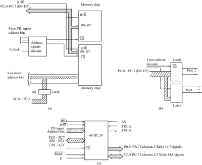
Memory chips and a very large number of IO peripherals (ports) can be interfaced because of the memory-mapped IOs (IO peripherals accessed like memory addresses) in 68HC11 when the MCU is used in the expanded mode. Figure 16.5(a) shows a memory-interfacing circuit. [Memory-mapped IO means IO address is considered same as memory address by the CPU. The instructions and control signals are the same for memory and IO operations.]
Additional Ports Using the Latches and Decoder When external additional ports are needed, 68HC11 can be used in the expanded mode to interface external latches and port chips. The decoder gives the outputs for the chip-select inputs to port chips. The decoder is given inputs from E clock and upper bits at Port B pins as the input. Since 68HC11 does memory-mapped IOs, the additional ports interface like the memory chips. IO addresses that are used are distinct from the memory (internal or external) addresses in the program. Figure 16.5(b) shows additional two ports using an interfacing circuit.
Ports B and C Reconstruction Using an External Chip MC68HC24 Port Replacement Unit When 68HC11 is used in the expanded mode to interface external memory chips, Ports B and C are lost. These can be reconstructed. An external chip, MC68HC24 (port replacement unit) is interfaced to five upper address signals, AD0−AD7 bus signals, Reset (active 0), IRQ (active 0), E clock, R/ W and AS signals from 68HC11. The chip recreates PB.0 to PB.7 (Table 16.7) and PC.0 to PC.7 (Table 16.8). Figure 16.5(c) shows ports-interfacing circuit for reconstruction of PB and PC.
When 68HC11 is used in the expanded mode to interface external peripherals, additional DMAC can be used for IO interfacing.
16.3.3 Serial IO Devices
SCI (Serial Communication Interface) 68HC11 has SCI (serial communication interface) for the UART. (Fig. 2.9(a) 10T and 11T formats) SCI does full duplex communication using TxD and RxD. Master SCI device means device transmitting presently. Slave SCI device means device receiving presently. The shaded bit, shown in Fig. 2.9(a), is used to send the address by the master to the slave so that only that wakes up. When the slave wakes up, it receives transmission from the master. Different SCI devices can thus connect on the common TxD and RxD lines.
Baud rate for SCI is selected when the select registers (at address 002BH) are set. Baud rate is made equal in each SCI device when the different 68HC11s communicate on common TxD and RxD lines (Table 16.9). DDRD.0 − DDRD.1 bits (at address 0009H) can be set differently in two SCI devices when UART communication occurs between 68HC11s. SCCR1 and SCCR2 at the addresses 002CH−002DH are two SCI control registers (Table 16.4). SCSR at the address 002E is SCI status register. SCI data transmits by write to TDR (SCDR at address 002FH). SCI data receives and is read at RDR (SCDR, which is also at address 002FH).
SPI (synchronous serial peripheral interface)
- 68HC11 has an SPI and it has full duplex communication with master and slave devices.
- Master mode in the SPI—the device sends the clock pulses for the slave to accept the bits at the clock-edges and receives the bits from slave SPI according to the master’s clock-edges. Slave mode in the SPI— the device receives the clocking pulses for the slave to accept bits from the master and send the bits to the master using the master’s clock (Table 16.9)
- DDRD.2−DDRD.5 bits at address 0009H (Table 16.3) have to be set differently in master and slave SPI devices at two communicating 68HC11s.
- An instruction using BSET or BCLR can enable and disable the SPI by writing 1 or 0 respectively, to b6 at SPCR (SPI control register). It is at address 0028H when the registers map to 0000H space (Table 16.3).
- The slave-select pin
 either connects to +5 V in normal use or in case of SPI, in a master 68HC11 SS output and in case of a slave SPI its is input when using SPIs for multi- processor serial synchronous communication.
 - Serial clock is programmable by pre-scaling bits. SPI can be programmed for −ve edge or +ve edge or both edge instances to enable synchronized reception of the transmitted bits.
- When SPSR is read it gives the status flags when SPI communication occurs.
- SPI data transmits by write to SPDR (address 002AH). SPI data receives and read at SPDR.
16.3.4 RS232 and RS485
UART output and input interface TxD and RxD pins of MCU to an RS232C port. Figure 3.18(b) showed how to interface a MAX 212. RS449 and RS485 are other recommended standards for serial UART communication at a higher rate and at higher distances. These use the twisted-pair cables.
16.4 INTERRUPTS
16.4.1 Non-maskable, Maskable Sources of Interrupts and Reset
Interrupt and reset are non-maskable sources. (Table 16.11) Order of increasing priority (priority for their handling) is as follows: XIRQ pin interrupt (if set non-maskable), illegal opcode SWI interrupt, COP (Computer operating properly) failure (due to watchdog timer reset) or COP clock monitor failure reset and reset.
These have no flags and mask bits (except XIRQ mask using X bit at CCR provided it is set during first 64-clock cycles).
These have five vector addresses between (10 bytes) FFF4−FFF5 and FFF8−FFFFH. The ISR address must be definitely defined at the vector address when using 68HC11. Bytes for three types of the resets and for illegal opcode can be distinct or same (if the programmer programs these to be same).
Maskable Sources are given in Table 16.11
Columns 1 to 3 of Table 16.11 give the priority-wise groups, their sources and flags in each group. Group 0 source has no flag but distinct vector addresses. Group 1, one of two sources has the flag and both have common vector address (FFF2H−FFF3H). Group 2, each source has a distinct mask, distinct flag and distinct vector address. Vector addresses decrease in decreasing order of priority. The addresses are between FFF0H−FFF1H and FFD8H-FFD9H. Group 3, each source among the seven has the distinct mask (common for overrun or frame error or no frame and RDR full) and distinct flag but a common-vector address (FFD6H−FFD7H).
Table 16.11 Priority-wise Groups and their Sources and Flags in each Group
5 Non-maskable Interruptsa or resets with 5 interrupt or reset vectors Group 0 |
XIRQ pin interrupt (if set non-maskable), illegal opcode SWI interrupt, COP (Computer operating properly) failure (due to watchdog timer reset), or COP clock monitor failure reset, and reset |
None |
INT_Mask1 Group 1 (masked by I bit) TMSK2 Group 2 |
Interrupt at IRQ or parallel IO handshaking port (masked by I bit or I and STAI bits, respectively) Real Time Interrupt |
STAF for parallel IO only RTIF |
TMSK1 Group 2 |
Timer IC1 capture |
IC1F |
TMSK1 Group 2 |
Timer IC2 capture |
IC2F |
TMSK1 Group 2 |
Timer IC3 capture |
IC3F |
OC1M Group 2 |
Timer OC1 capture |
OC1F |
OC1M Group 2 |
Timer OC2 capture |
OC2F |
Timer OC3 capture |
OC3F |
|
OC1M Group 2 |
Timer OC4 capture |
OC4F |
OC1M Group 2 |
Timer OC5capture |
OC5F |
TMSK2 Group 2 |
Timer Overflow |
TOF |
TMSK2 Group 2 |
Pulse Accumulator Overflow |
PAOVF |
TMSK2 Group 2 |
Pulse Accumulator Input edge |
PAIF |
SPCR Group 2 |
SPI transfer-over from SPDR or into SPDR |
SPIF |
SCCR2 Group 3 |
SCI TDR empty, TDR control, Receiver overrun or frame or no frame or Receiver full and Idle SCI |
TDRE, TC, OR, FE, NF, RDRF, IDLE |
SWI Group 0b |
SWI instruction [Section 16.2.2(6) interrupt program flow control] |
None |
a Five non-maskable interrupts or resets with five interrupts or reset vectors.
b Sixth non-maskable interrupt source, because it is software instruction.
16.4.2 Servicing of Interrupts
68HC11 interrupt service structure (Section 5.1) has the following features:
- Reset has a vector address unlike 8051.
- Masking of interrupt sources by the control bits and by setting I and X bit in CCR for maskable interrupts. Interrupt masks are at the PIOC, OC1M, TMSK1, TMSK2, SPSR and SCCR. Flags are at TFLAG1, TFLAG2, SPSR and SCSR (Tables 16.3 and 16.11).
- Identification of source of interrupt is by flags in status registers.
- Finding the ISR address from a vector address that is distinct for each source of interrupt (no common vectors). Only IRQ and parallel handshaking port IO have a common vector.
- Auto pushing of nine bytes before the ISR starts in the following order—PCL, PCH, IYL, IYH, IXL, IXH, ACCA, ACCB, and CCR on stack. On return from ISR by RTI instruction, nine bytes pop back in reverse order. (Only PC pushes on stack in 8051 and 80x96. Return from an ISR enables all those interrupts that were of lower priority. They disable for servicing only during the ISR run. PC pops on return.)
- Default priority assignments.
- No in-between preemption (except by XIRQ if set so) by higher priority interrupt.
16.5 PROGRAMMABLE TIMER
Free-Running Counter / Timer TCNT 68HC11 has one programmable timer, TCNT. It is programmable only for the prescaling factor. It functions as a 16 bit free-running counter (FRC) (Section 6.2). TCNT counts can be read at 000E−000F (higher-lower bytes) if register space of memory maps to 0000H (Table16.3). After a read, it can be used for save as such or after increment, decrement, complement, shift operations or arithmetic or logic operations.
TCNT is programmable for four clocking rates by pre-scaling (Section 6.1.1(B)). With 8 MHz XTAL, the TCNT clock inputs are at every 0.5 μs. Pre-scaling factor can be programmed by PR0 and PR1 bits for 1, 4, 8 or 16. Then clock gives inputs for the count by TCNT after every 0.5 μs, 2 μs, 4 μs or 8 μs, respectively. Example 6.2 showed pre-scaling in 68HC11.
16.5.1 Timing Signal Generation— TCNT Overflow and Real Time Clock Interrupts
Timing signals generate on (i) TCNT overflow interrupt, (ii) real-time clock periodic interrupt and (iii) out compare interrupt. TCNT overflow signals can be used for applications.
(a) TCNT Overflow Interrupts Overflow interrupts (TCNT) will be after 216 multiplied by 0.5 μs or 2 μs or 4 μs or 8 μs. PR1–PR0 are written into TMSK2 (Table 16.3). Bit TOI is overflow interrupt mask bit. A mask bit is as per the corresponding bit set or reset at TMSK2 register. Mask instruction BSET 24H, mask or BCLR 24H, mask can be used to set or clear the bit. Control register TMSK2 register is direct addressable register. Assume that register space is set to map to beginning from 0000H.
(b) Real-Time Interrupts at Periodic Intervals A pair of bits RTR0–RTR1 at PACTL sets the period. The period can be set as 4.096 μs or 8.192 μs 16.384 μs or 32.768 μs when using 8 MHz crystals. RTII mask bit is at TMSK2. It enables or disables the real-time interrupts. Flag RTIF sets at the TFLG2 on each interrupt (Table 16.3)
16.5.2 Input Capture
TCNT can be used to provide three input captures. The capture is at the transitions at three input pins. IC1 to IC3 inputs are at Port A pins (Table 16.6). Registers given in Table 16.3 for the control and mask bits are used as follows:
- Eight-bit TMSK1 register has three mask bits, IC1I to IC3I for masking interrupts from three input-capture actions with TCNT. BSET 22H, mask or BCLR 22H, mask can be used when TMSK1 is direct addressable (maps to register space beginning from 0000H). Flags are at TFLAG1 register.
- A capture is of a 16-bit TCNT value and captured value saves at TIC1, TIC2 or TIC3.
- A pair of TCTL2 registers controls action on each input-capture. Two bits in the pair are written to define one of the four actions— whether the capture is at positive edge or negative edge or at both edges or the capture is disabled.
16.5.3 Timing Measurements of External event
68HC11 provides for external event inputs. They are identified by either positive edge, negative edge or any of the edge. Input-capture feature in 68HC11 measures the instantaneous time at an event. When not using the out compare 1 (Section 16.5.4) feature and pulse accumulator counter feature, an event time can be measured by input at PA.7 pin using the input edge interrupt (Section 16.5.5). Pulse width can be measured by two captured successive values at TICx register. The time is captured from continuously running TCNT. Successive captures are programmed for positive and negative edges with each capture programmed for any (rising or falling) edge during the pulse width measurement.
16.5.4 Out Compare
TCNT can be used to provide five outputs (Table 16.6) on compares. Table 16.6 the OC outputs at Port A. The uses of registers and control and mask bits in them are as follows:
- A comparison of 16-bit TCNT value at an instance is for equality with one of 16-bit registers—TOC1, TOC2, TOC3, TOC4 or TOC5 at addresses given in Table 16.3.
- TCTL1 register has 4 pair of bits. These control the four out compare actions of OC2 to OC5. A pair of bit OL.x–OM.x is written for an action. (x = 2 or 3 or 4 or 5.) OL.x (called OC label bit) sets or resets to define output pin OC.x level 0 or 1. OM.x (called OC mask bit) sets or resets to define output pin mask set or reset. If pin output masked, the output at a pin (OC2–OC5) remains same as before. Control of individual action at four output pins is thus using TCLT1 four pair of bits.
- Eight-bit TMSK2 register has five mask bits—OC1I to OC5I for the masking interrupts from five out compare actions with TCNT. Flags on OC1I to OC5I set at the TFLAG1 register.
- The OC1 to OC5 outputs are at Port A pins. The initial value(s) set or reset at the output Port A as follows: It is as per the written byte or bits to Port A at address 0000H. Port A bit initial value can be written by BSET 00H, mask or BCLR 00H, mask.
- Using CFORC, (timer Compare FORCE register)’ the processor sets OC1 to OC5 outputs using an OC1 comparison event alone. After setting a bit(s) into CFORC, an OC1-OC5 pin(s) can be forced as per result of OR operation with earlier value at Port A pin with the corresponding bit at CFORC. If a bit at CFORC is set to 1, the corresponding pin sets immediately to 1. This will be irrespective of whether or not previously the Port A pin set to 1 or the previous out- compare action set the output pin. OC1 out compare therefore can be used to initiate five actions.
- Eight-bit OC1M register (Table 16.3) has five mask bits for masking the outputs at pins for OC1 to OC5 when using the OC1 out compare action. If masked, an output pin for OC1-OC5 on out-compare action at OC1 does not affect. If not masked, the pin becomes as per OC1D register five bits on successful comparison. Out compare 1 action can thus be used to control simultaneous action at any of the five output pins using OC1M and OC1D. Let us consider an example. BSET 0DH, mask or BCLR 0DH, mask can be used when OC1D is direct addressable (maps to register space beginning from 0000H). Provided OC1M does not mask, it defines the OC.x output OC. 1 and OC.2 = 1 if mask = C0H in the BSET instruction.
16.5.5 PWM Outputs
PWM outputs can be generated at OCx (x = 2–5) output pins. One of the four TOC2–TOC5 register loads the time TOCx (x = 2-5) on out compare. Out-compare occurs when TCNT counts become equal to TOCx. An OCx (x = 2–5) is unmasked for a PWM output and set the output to 1 on equality. PWM output at OCx is also programmed to 0 on each TCNT overflow interrupt. Pulse width percentage is calculated by [100 − (216 − TOCx) × 216].
16.5.6 Frequency Measurement
Frequency means measuring the number of pulses found per second. The pulse accumulator feature for event inputs (count inputs) at PA.7 can be used for measuring frequency. PACNT can be loaded with a value x at first input positive edge after reading TCNT register. PACNT overflow interrupt can read TCNT again. Difference between two values is time in (256−x) pulses. Section 16.5. describes pulse accumulator feature in 68HC11.
Frequency can also be measured by finding the captured time difference between two positive edge captures at an input capture pin. Section 16.5.2 describes the input-capture feature. The reciprocal of time difference is the frequency. FDIV instruction can be used for this. The values can be averaged in case of frequency values having deviations due to some instability.
16.5.7 Pulse Accumulator Counter
A pulse accumulator has many functions. Some of them are as follows: (a) Counting of external positive- edged or negative-edged inputs, (i) Finding the pulse width of the input pulses using positive input edge interrupt and PACNT overflow edge interrupt. (ii) Executing an ISR on input at PA.7 when neither OC1 nor pulse accumulator feature used. (b) Pulse accumulator, two interrupts can be used by reading TCNT at each interrupt for finding the pulse width.
Eight-bit PACNT register is for the counts at the pulse accumulator inputs. It can also be loaded with any value between 00H and FFH. TCNT cannot load, it is read only (Table 16.3). It can receive count inputs from Port A PA.7 pin, provided the PACTL control bit b7 is set. This is like the data direction register bit for PA.7 pin.
PA.7 pin is for OC1 output and PA.7 input from an external device. It can be selected as a pulse accumulator count input by setting b6 of PACTL to be equal to 1 when b7 is also reset to 0 so that PA.7 is input as well as generate internal input to pulse accumulator.
Pulse accumulator functions as a counter for a number of events through PA.7 when bit 5 is reset to 0. The input edge can be selected as the rising edge by setting b4 of PACTL to be 1. Pulse accumulator input edge at PA.7 also results in the pulse accumulator input edge interrupt if PAII bit in TMSK2 (as well as I in CCR) has enabled the interrupt. The flag sets at PAIF in TFLG2. This interrupt can be useful even when the pulse accumulator feature is not used. It can be used to initiate an ISR on positive edge or on negative edge as per the b4 bit of PACTL.
PACNT overflow (count increment after FFH becomes 00H) can cause the pulse accumulator overflow interrupt if PAOVI bit in TMSK2 (and I in CCR) has enabled the interrupt. Flag sets at PAOVF in TFLG2 (interrupt vector addresses for PAOV interrupt are FFDCH–FFDDH).
16.6 APPLICATIONS OF ANALOG INTERFACING
Figure 2.12 showed an MCU unit internal ADC feature (also refer Section 2.3.10). Figure 16.2 showed that there is an ADC internal device in 68HC11A8. There is an in-built sample hold amplifier for each channel and analog multiplexer unit for the channels. The two inputs are VREF+ and VREF− (Option 1, Fig. 2.12) that set the voltage measurement range. The range sets between 0 V to a maximum = VREF+. 68HC11 analog channels can be interfaced to analog inputs in the range of VREF+ and VREF− either directly or through an appropriate signal condition circuit for gain, offset, other compensation and non-linearity effects compensation signals. ADC can be used in a single select channel or the multiple channel mode. A scan rate can be specified. It is done by using TCNT overflow or RTII interrupts or OC.x interrupts. An interrupt initiates conversion(s). ADC can be used in single-scan or multiple-scan mode. ADC conversion time is controlled by internal E clock.
Port E pins are used to get analog input from the different input analog channels (Table 16.10). Table 16.3 listed the register addresses for ADC. CONFIG register b7 enables ADC channel input to Port E when reset to 1. CONFIG register b6 when set to 0 selects the E clock for ADC channels. ADR1 to ADR4 are registers for the ADC results in four channels AD in a 68HC11 A8 version.
ADCTL register is for AD control. It is programmed as follows:
- b6 selects if a single scan or a continuous scan is to be done.
- b3−b2−b1−b0 at it selects multiple channels when b5 is reset and single channel as per b3−b2−b1−b0 when b5 is set.
- Examples of using b3−b2−b1−b0 are as follows: b3−b2−b1−b0 = 0000 means channel AN0, b3−b2−b1−b0 = 0011 means AN3 channel 3.
- There are exceptions. b3−b2−b1−b0 = 1110 means Vref/2 is the input. AN input = 2 × (Vref/2) Volt will result in all 1s in the ADC outputs. b3−b2−b1−b0 = 1101 will assume Vref as channel input to test if become equal to bits = 0. b3−b2−b1−b0 = 1100 will assume Vref+ as channel input to test if all bits become equal to 1s.
ADCTL register is for AD status register when read. b7 shows that when conversion of channel (s) is over, it can be set by write using BSET 30H 80H instruction. It clears any write to ADCTL.
SUMMARY
- 68HC11 MCU is 8-bit microcontroller. Configuration and initialization options are defined in first 64-clock cycles of the processor after reset.
- MCU has nine CPU registers for accumulator, double accumulator, CCR, index registers IX and IY and 16-bit S.
- Inherent, immediate, direct, extended and indexed IX and indexed IY addressing modes are used in the instruction set.
- MCU has Princeton architecture of memory. Program and data can thus be in same memory space. It uses big-endian data alignment.
- MCU has memory mapping of registers and internal RAM by INIT register bits. Mapping enables use of direct address in instructions like BSET or BCLR for registers or RAM.
- On-chip registers and internal RAM can be mapped to x’000H and x000H. The x and x’ are four bits each. These are specified at the INIT register.
- MCU has a programmable free-running counter. The counter associates pre-scaling bits for clocking inputs.
- MCU has several innovative features like realtime interrupts, pulse accumulator counter, five out-compares events, three input captures and five force out-compare outputs on an event.
- MCU can be used for four PWM outputs through four out compare actions in conjunction with TCNT overflow interrupts. PWMs enable multiple number of DAC outputs.They enable DC and servo motors control.
- MCU has SPI for full duplex synchronous serial communication along with the clock bits sent by the master. SPI can be used for multiprocessor communication of serial bits in master-slave mode with slave clocked by the master clock.
- MCU has SCI for full duplex asynchronous serial (UART) communication at selected (programmed) baud rate. SCI can be used for single or multiple device or multiprocessor communication of serial bits through TxD and RxD lines.
- Most interrupt sources, power-up reset and watchdog-timer reset have independent vector addresses for interrupt servicing and for reset.
- There are STOP and WAIT instructions. They are used for power dissipation management.
KEY TERMS
Compare force register: COFORC register in 68HC11—, a write to which forces 1 at specified Port A out compare output pins by logical ORing of earlier port outputs with the force register bits. Forced outputs are at the instance OC1 register values equal TCNT.
CONFIG: A configuration-register in 68HC11. It has bits to disable or enable use of security bits, COP watchdog timer, internal ROM and internal EEPROM.
COP: Computer operating properly interrupts due to NOCOP (not operating properly). It is when a watchdog time out action or clock failure occurs.
Data direction register: A register to specify direction of each pin of a port associated with that. For example, bit 3 at a DDR (b3) = 0 will make port pin 3 as input pin and bit 0 at DDR (b0) = 1 will make port pin 3 as output pin.
Direct address: 8-bit address used in instruction to specify address of a memory or register in a block, which is mapped to 0000H in 68HC11.
Expanded mode: A mode in which external peripherals are interfaced to an MCU using CPU bus signals.
Full duplex communication : Transmission and reception can occur at the same instances on two distinct lines or channels.
Handshaking mode: A mode in which (a) port latches an input on a strobe signal from external device. Then sends the acknowledgement of data strobe and interrupts the processor (after latching the input). This enables an ISR reading the port, or in which (b) port sends on write, a buffer full signal. The external device sends an acknowledgement of receiving buffered byte. The port sends interrupt to the processor. This gives port buffer empty message internally and therefore ISR can initiate next action.
Index register: A register IX or IY of CPU to specify a memory or register address by its sixteen bits. It is used in 68HC11 for base address or source address or destination address or queue pointer for queue top or tail (which auto increments after use for the next) or pointer to point to a table or block entry when offset is specified in the instruction or when this register auto increment feature is used.
Inherent addressing: Addressing mode in which operand is either specified within the opcode byte itself or is inherent. For example, PSHX for pushing IX 16 bits onto stack.
Input capture: An action of capturing time (instance) at a running timer on an event for example input pin rising edge or falling edge or level 0 or 1. A capture can also trigger other events or interrupts or outputs. It is used for timing measurements between the events or for triggering the real-time actions, or chain of actions after the detecting an event.
Master: A device that sends the bits at instances specified by itself so that another device should synchronize itself to receive these at correct instances. The master also sends the clock pulses seperately or puts clocking or synchronising information along with data.
Memory mapping: Mapping is essentially a change of the base for a memory or register block. It is a way in which a memory block is specified. For example, internal RAM memory allocated to some memory space specified by another address space or on chip registers allocated to some memory space specified by another address. Registers of 68HC11 when mapped to memory space at 0000H will have addresses beginning from 0000H and when mapped to 1000H will have addresses beginning from 1000H. Similarly, internal RAM space can be mapped to an address block.
Out compare: An action and output at specific time(s) after comparison between the time values specified in an out compare register and endlessly running timer. Comparison is similar to as in a preset alarm in a clock. It is used in number of applications, for examples, for output change at specified instance(s) or to synchronize an event(s) or periodic instances of outputs or interrupt(s) or periodic output pulses of specified width for generating PWM outputs.
Programmable timer: A timer, which can be programmed for periodic overflow actions and interrupts on timeouts, for out compares, for input captures and for the rates of internal clocking (in 68HC11).
Pulse accumulator counter: A counter for accumulating the event occurrence for the counts and generate interrupts at overflow and/or at the input edge at the count-input.
Real-time Interrupts: A periodic occurrence of interrupts with period programmable as one of the four values (in 68HC11) and which once initiated continues to occur.
Serial communication interface: An interface device in 68HC11 present internally in 68HC11 for UART communication from one or between several UART devices using common TxD and RxD lines between them.
Serial peripheral interface (SPI): An interface device in 68HC11 present internally in 68HC11 for synchronous serial communication in which a master SPI sends the serial data bits as well as the clock to specify the instances at which a bit should be accepted by slave and can be sent (bytes) by the slave also as the response.
Single-chip mode: A mode in which external peripherals are not interfaced to an MCU and only ports of MCU are interfaced to external peripherals or devices (like display unit or keyboard or motor).
Slave: A device, which receives or sends the bits at instances specified not by itself but by a master.
STOP: An instruction which sets a bit in CCR and which freezes the clock activity or clocking in the CPU till an interrupt.
Vector address: An address to specify the higher and lower bytes of the ISR or reset. CPU vectors to that address by a branch action or by routine call on interrupt or reset signal.
Wait: A wait at a certain point in the program till an interrupt occurs. The clock or timer does not freeze, only execution and fetch units action freezes.
Watchdog timer: See COP.
REVIEW QUESTIONS
- Describe 68HC11 architecture. List the innovative features with respect to classic 8051 architecture. How do the push and pops occur using S?
- List the addressing modes used in 68HC11−MCU instruction-set. Give five exemplary uses of each mode.
- Describe branch, conditional branch, call and return instructions in 68HC11.
- Explain STOP and WAI instructions.
- List the ‘config’, ‘option’, ‘init’, port and timer control, mask and status registers in 68HC11.
- How do you map on-chip registers for direct addressing in 68HC11? How do you get the advantage of direct addressing for the setting or clearing RAM or register bits?
- Draw a 68HC11 memory map. List innovative map features with respect to the 8051 architecture.
- Explain IO ports in single- chip mode and the port multiplexing signals in the expanded mode.
- Describe functioning of input captures and out compares in 68HC11. How do you initialize the OC outputs?
- Explain 68HC11−family real-time clock interrupts. How do these differ from out compare interrupts programmed for periodic comparisons in 68HC11?
- How do real-time clock interrupts differ from software-timer interrupts of 80196?
- List non-maskable and maskable interrupts in 68HC11. Draw a table of interrupt vectors according to hardware priority of each source group.
- Describe pulse accumulator counter device application.
- Explain ADC unit features in 68HC11.
PRACTICE EXERCISES
- Prepare a list to show how 68HC11 differs from 8051.
- Prepare a list of interrupt flags, which can set in TFLG1 and TFLG2 registers on the interrupts.
- Compare the interrupt source flags provided in 68HC11 with that in 80196.
- Compare the interrupt mask bits provided in 68HC11 with that in 80196.
- Compare the interrupt source flags provided in 68HC11 with that in 8051/52.
- Compare the interrupt mask bits provided in 68HC11 with that in 8051/52.
- Search the Web and find the most used sources for the development tools for 68HC11 and 68HC12.
MULTIPLE CHOICE QUESTIONS
It is implied below that questions pertains to 68HC11 family MCU.
- CPU registers __________.
- S has an on-chip register address like SFR in 8051
- A, B, D, IX, IY and S have on-chip register addresses like SFRs in 8051
- None of the A, B, D, IX, IY and S have on- chip register addresses
- IX and IY have on-chip register addresses like SFRs in 8051
- Which of the statements is correct?
- SP and CCR of 16 bits and push of each bytes is after S decrements
- S and CCR of 8 and 16 bits and push of each byte is after S decrements
- S and CCR of 16 bits and pop of each byte is after S decrements
- S and CCR of 16 and 8 bits and push of each byte is before SP decrements
- Memory mapping by INIT register write creates __________.
- different 4 kB memory block for internal RAM and on-chip registers
- same 4 kB memory block for RAM and on-chip registers
- different 256 B memory block for internal RAM and on-chip registers
- same 256 B memory block for internal RAM and on-chip registers
- Direct address is __________.
- an 8-bit address for internal RAM and on-chip registers
- an 8-bit address for internal RAM or on-chip registers
- an 8-bit address for BSET and BCLR instructions only
- not used
- Pulse accumulator counter is used __________.
- to count external inputs at PA.7 pin input and overflow interrupt
- to capture time and count on the input events at PA.7
- for input edge and overflow interrupts and for counting and PWM outputs
- for input edge and overflow interrupts and for counting
- Which of the statements is correct?
- Both TCNT and PACNT are free- running counters of 16-bit each
- TCNT and PACNT are 16-bit free- running counters and 8-bit counter
- TCNT and PACNT are 16-bit free- running counter and 16-bit external inputs counter
- TCNT and PACNT can get pre-scaled inputs from internal clock
- Which of the statements is correct? There are
- only one interrupt vector, four mask bits for SCI RF (= RI), TDRE (= TI), IDLE OR, NF and FE ISRs
- two interrupt vectors, four mask bits for SCI RF, TD RE, OR, NF and FE interrupt
- one interrupt vector, seven mask bits for SCI RF, TDRE, OR, NF and FE interrupts
- two interrupt vectors seven flag bits for SCI RF, TDRE, OR, NF and FE interrupts
- Using TCLT2 for capture on each input event or input events can be defined by __________.
- rising edge or falling edge or any edge or can be disabled
- rising edge or falling edge or any edge
- rising edge or falling edge or cannot be disabled
- rising edge or falling edge
- Using OC1M can mask on each out compare event at OC1 __________.
- each OC pins output and OC1 interrupt
- OC1 pin output and OC1 interrupt
- each OC pins output and each OC interrupt
- each OC pins output
- ADCTL programs __________.
- single channel, multiple channel, self-test, scan or multiple ADC scans
- multiple channel, self-test, scan or multiple ADC scans
- self-test, scan or multiple ADC scans
- number of analog channels controlled
FILL IN THE BLANKS TYPE QUESTIONS
- There are _____ CPU registers, PCL, PCH, _____, IYH, _____, _____, ACCA, _____ and CCR and internal buses in 68HC11.
- 68HC11 is an _____ microcontroller. MCU is designed using _____ technology. Clock frequency can be reduced to _____.
- The power dissipation is _____ in the state of stop or wait.
- The clock cycle frequency is X-Tal frequency divided by _____.
- Two external interrupts (one definable as _____) are given through _____ and _____ pins. _____ interrupt can be made a non-maskable interrupt within _____ pin is also used to give _____.
- _____ is a register in 68HC11, a write to which forces 1 at specified Port A out compare output pins by logical ORing of earlier port outputs with the force register bits. Forced outputs are after the _____ register values equal _____.
- _____ is a configuration-register in 68HC11. It has bits to disable or enable use of _____, _____, internal _____ and internal _____.
- _____ is a register to specify direction of each pin of a port associated with that.
- Direct address is _____ address used in instruction _____ to specify address of a memory or register in a block, which is _____ to 0000H in 68HC11.
- Full duplex communication mean _____ and _____ can occur at the same instances on two distinct lines or channels.
- _____ specifies a memory or register address by its sixteen bits for base address or source address or _____ address or _____ pointer.
- _____ addressing mode in which operand is either specified within the opcode byte itself. Example is _____ for pushing _____ onto _____ bits onto stack.
- _____ is an action of capturing time (instance) at a running timer on an event for example input pin _____ edge or _____ edge or level _____ or _____.
- _____ is a device which sends the bits at instances specified by itself so that other device should synchronize itself to receive these at correct instances. The master also _____ clock pulses.
- Registers of 68HC11 when mapped to memory space at _____ will have addresses beginning from 0000H and when mapped to _____ will have addresses beginning from 1000H.
- _____ an action and output at specific time(s) after comparison between time specified in an _____ register and endlessly running timer _____.
- _____ is a timer in 68HC11 that can be programmed for periodic overflow actions and interrupts on timeouts, for _____, for _____ and for the rates of internal clocking.
- _____ is a counter for _____ the event occurrence for the counts and generate interrupts at overflow and/or at the input edge at the count-input.
- _____ means periodic occurrence of interrupts with period programmable as one of the _____ values (in 68HC11) and which once initiated, continues to occur.
- Serial peripheral interface (SPI) is a device in 68HC11 present for _____ serial communication in which a master SPI sends the _____ as well as the clock to specify the instances at which a bit should be _____ by slave and can be sent (bytes) by the slave also as the response.