
The Evolution of the MFP from the Fax Machine
PC AND FAX MACHINE LINKED
In August 1983, Takaho Koshiishi of the Ricoh Company, Ltd., in Japan, filed for a patent covering a combination of a facsimile apparatus and a personal computer. The latter was connected to the facsimile apparatus through a parallel interface. The combination had four operation modes:
1. A recording mode where the data from the computer was recorded by the printer in the fax apparatus
2. An image input mode where data from a scanner in the fax apparatus was input to the computer
3. A transmission or transfer mode where the data from the computer was transmitted to another fax apparatus
4. A reception/transfer mode where the data from another fax apparatus was input to the computer
Koshiishi stated that a fax apparatus is capable of reading, recording, and communicating image data with relatively high accuracy. Therefore, if the conventional fax apparatus is modified to be connectable with a personal computer to permit transfer of image data between the fax machine and the computer, it will process the data in various manners and store the same on the computer side, to return the data back to the fax apparatus for printing, and to transmit the data from one fax machine to another, as required. (See Figure 1.1.)

Figure 1.1 Modified fax machine linked to personal computer. (from Koshiishi’s patent, filed in Japan, August 1983)
Patent #4,652,933 was granted to Takao Koshiishi from a U.S. filing in 1984.
EXTERNAL INTERFACES BETWEEN FAX AND PC
Another inventor, Paul Lin, of Taipei, Taiwan, filed initially in 1987 for a U.S. patent titled “Interface Device for the Intercommunication of a Computer and a Fax Machine,” in which he made the following comment:
U.S. Pat. #4,652,933 discloses a system comprising a computer and equipped facsimile machine, in which the facsimile machine is connected between the computer and a cable to the central office. The facsimile machine can be used as the printer or the scanner for the computer. In this device, the fax machine is greatly modified. Therefore, the user cannot use his original fax machine, and has to purchase a newly equipped fax machine to build such a system. If we want to modify the original fax unit to such an equipped fax machine, the cost of modification is extremely expensive (perhaps, it appeared to be so at that time). Moreover, such a device lacks informing means to advise the computer of the arrival of information (either transmitted from the central office or scanned from the fax machine), in advance so that the computer can prepare to receive it. Without the precedent information of the arrival of information, the computer may sometimes fail to receive it successfully.
Following this statement, Paul Lin stated that the chief object of his invention was to provide an interface device that would make it possible to utilize an available fax machine as the printer and scanner of a computer without any change in the structure of the fax machine or the computer, while preserving all the inherent capability or the fax machine to communicate with the central office or remote fax terminals. U.S. Patent #4,991,200 was granted for this invention. It was followed by several other patents by other inventors interested in providing such an interface. This approach appears to have had some merit at that time. However, it never established a trend or an acceptable product.
A MULTIFUNCTION DEVICE
Closer to present-day multifunction peripherals, Toshiro Kita and nine associates of the Sharp Corporation, Osaka, Japan, proposed a machine coupled to a PC also through a parallel interface to accomplish various functions. A patent application titled “Image Processing Device of a Multifunctional Type” was filed in Japan on September 30, 1986. This machine had an on-line and an off-line control status.
In the on-line control status, the following functions were selectively executed according to control commands provided to the device by the PC connected to it:
Image input function. Image information read by the image read unit (the scanner) was transferred to the PC on the data bus according to control commands.
Image print function. Image information sent from the PC to the image record control unit was printed.
Fax function. Image information received by the device through the telephone line was transferred to the PC. Also, image information inputted from the PC was transmitted by the device through the telephone line.
In the off-line control status, the device operated independently from the PC and the following functions were performed selectively:
Copy function. Image information read by the image read unit (the scanner) was supplied to the image recording unit (the printer) on a data bus and printed according to the control information transferred from the main control unit.
Fax function. Image information read by the image read unit (the scanner) was transferred to the fax control unit and then through the telephone line, according to the control information outputted from the main control. The image information received through the telephone line was recorded by the printer in the MFP.
A block diagram of the multifunction device connected to a personal computer as described in Kita’s patent is shown in Figure 1.2. A main CPU controlled the MFP in accordance with each of the system programs stored in a ROM in advance. This main CPU was connected to a common data bus DB, an address bus AB, and a control bus CB. In the MFP, the ROM and the following units were connected to each of the buses DB, AB, and CB and controlled by the main CPU: a RAM, a CCD read control portion containing a slave CPU, an image data codec control portion containing a slave CPU, a transmission control portion containing a slave CPU, an interface connecting to the operation control panel, and a parallel interface to connect the MFP to the PC. In addition to the system programs in the MFP, the ROM had a command analyzing portion for transferring data to and receiving data from the PC.
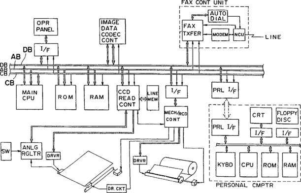
Figure 1.2 Block diagram of multifunction PC peripheral. (from Kita’s patent filed in Japan, September 1986)
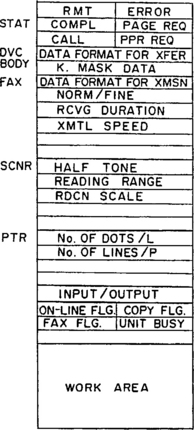
As shown in Figure 1.3, the RAM had a plurality of stored areas. These included the status of the MFP, unit setting areas where values relative to respective functions were stored, a flag area, and a work area, which included various buffers and similar devices as required.
The CCD read control portion in the MFP was operated when the machine functioned as a fax device in a transmission mode, a copy mode, or a scanning mode. The mechanism and record control portion included a slave CPU and functioned in a printing mode in addition to the preceding modes. The combination of the CCD read control portion with the mechanism and the record control portion was substantially the same as that of generally known fax machines of that period. The CCD sensor carried out the scanning operation by timing pulses transferred from a driver, controlled by the CCD read control portion. Analog signals outputted from the CCD sensor were supplied to a regulating circuit. There they were converted to a digital form in accordance with a predetermined density or slice level. The image data in digital form was supplied to the CCD read control portion. When the half-tone mode was selected, the analog signals outputted from the CCD sensor were converted to a digital form according to a predetermined half-tone level. The image data obtained either way was stored in a line memory connected to the CCD read control portion, which had a capacity for one line of a document. Then the data for each line was outputted to the data bus DB. A control section of the mechanism and record control portion drove a motor for moving the CCD sensor in a subscanning direction to produce a line by line reading operation.
The image data codec controlled the encoding of modified Huffman (MH) or modified read (MR) compression codes of the CCITT standard into binary data and the decoding of data into original form. The image data codec control portion operated when (1) the device was in a fax status, (2) image data read by the image scanner was compressed and then transferred to the PC, (3) compressed data sent from the PC was recorded by the image printer, and (4) binary image data outputted from the PC was transmitted by the fax function of the MFP. The image data codec control portion included algorithms, buffers, and similar components for encoding and decoding.
The unit for controlling transmission and reception via facsimile was substantially the same as that in typical fax machines. The fax transmission control portion contained a slave CPU for controlling the transmission procedure based on the CCITT standard and exchanged data with the data bus CB to carry out the procedure. The fax transmission portion was connected to the telephone line through a modem and a network control unit (NCU). An automatic dial unit connected the circuit according to dial information provided by the personal computer. In a manual dialing operation, a telephone connected to the NCU.
The parallel interface for connecting the PC to the MFP was provided with a buffer for data of 1 byte, for example. The PC supplied the parallel interface with various kinds of commands and data to enable the units just described to transfer data to each other. In this invention the PC was not altered in construction from any other PC and was connected to the MFP through a cable as shown in Figure 1.2. The PC controlled the MFP by outputting various commands stored in advance in its RAM or ROM. These functions could be realized by operating the keyboard of the PC. Also, image data supplied by the MFP could be displayed on the CRT of the PC and/or filed on a floppy disk by the PC. Additionally, image data produced according to the program of the PC could be transferred to the MFP for recording and/or transmitting via facsimile.
Toshiro Kita and his associates filed in the United States for a patent covering this invention during September 1987 and were granted U.S. Patent #4,910,607 in March 1990. In December 1989, they made another almost identical filing except for one added claim and were granted U.S. Patent #5,021,892 in January 1991. Although these inventors at the Sharp Corporation obtained early patents for MFP machines, the Sharp Corporation did not immediately introduce machines of this type to the market. In March 1989, Canon introduced a very expensive machine capable of scanning and printing for computer fax. This machine, designated Fax-L6500, sold for a list price of $34,000 in the U.S. market. Despite the huge drop in the prices of MFP machines since then, this model was not discontinued until 1996. During September 1991, Canon introduced another MFP, model L-4600, with capabilities similar to those of the L6500. Its list price was $20,000.
In June 1993, Ricoh introduced the first reasonably priced machine, their Fax 3500L, with multifunctional capabilities. It offered an optional printer interface, enabling it to function as a printer for a computer. Optional PC-Fax Expander software made possible faxing directly from a PC with 200-dpi scanning and printing. This model listed for about $3,800 in the U.S. market. During 1993, a few other manufacturers introduced MFP machines at comparable list prices. By 1994, fourteen companies had introduced about thirty MFP models.
By 1998, every manufacturer of fax machines had introduced several models of MFPs to the market. They were available with inkjet printers for less than $500 and were offered with direct thermal printers for less than $200. At various price levels, depending upon required features, they have received broad acceptance in medium and small office/home office (SOHO) business categories. With expanded features, they have also found a place in large corporate offices.
MULTIFUNCTION PRINTER
On June 30, 1994, Yasuo Egashira and Isao Yamasaki of the Matsushita Electric Industrial Company of Osaka, japan, filed for a patent for a multifunction printer. After they filed in the United States in 1995, U.S. Patent #5,567,068 was granted in October 1996. Although the claims of this patent cover primarily a specific construction of a printer, it describes the basic functions of a multifunction printer as illustrated in the block diagram of Figure 1.4, when the facsimile function is provided in the unit.

Figure 1.4 Block diagram of multifunction printer with fax function. (from patent of Egashira and Yamasaki, filed in Japan in 1994)
The components of this device are as follows:
A control panel (labeled 1 in Figure 1.4) having various keys for selecting a scanner mode, a printer mode, a copy mode, a data transfer mode, and a facsimile mode
A controller (2) that, when one of the selection keys is pressed, outputs a control signal dealing with data received via a network control connected to a communication line
An image reader (scanner) (3) that reads data line by line and outputs such data
A driving unit (4) providing paper transfer
A printing section (5) for printing input data onto paper
A unit (6) that processes data obtained via the scanner (3) and outputs it to a personal computer in response to a control signal delivered from the controller (2) when the scanner mode is selected, and that processes data obtained from the scanner and outputs it to the printer (5) in response to a control signal delivered from the controller (2) when the copy mode is selected
A printer processing unit (7) that converts data received from a personal computer into font data including characters and outputs the resultant data to the printer (5) in response to a control signal from controller (2) when the print mode is selected
Data transferring means (9) that, when the print mode is selected, transfer data received from a personal computer to the communications line via a modem (8), and also transfer data received from the communication line to a personal computer via the modem (8)
A facsimile processing unit (10) that, when the facsimile mode is selected, binarizes and compresses data that is received line by line via the scanner (3) and transmits the resultant data to the communication line via the modem (8); it also expands data that is received from the communication line via the modem (8) and outputs the resultant data to the printer (5) in response to a control signal from the controller (2)
As mentioned previously, some machines that are classed as MFPs do not include the fax function. When it is omitted, the block diagram would appear as shown in Figure 1.5.

AN MFP FOR COMBINING AND ROUTING IMAGE DATA
Today’s technology may be presented most conveniently by describing a multifunction machine for combining and routing data. U.S. Patent #5,701,184 was granted in December 1997 to Tetsuro Motoyama of the Ricoh Corporation of Tokyo, Japan. Such a machine performs a number of functions. It serves as a digital copier that reproduces scanned image data, a printer that prints image data from a computer, and a facsimile device that sends and receives fax image data. Image data from a number of sources may be combined to form merged image data. This merged data may then be conveyed to a number of user-selectable destinations, such as a printer, a host computer, or a fax device.
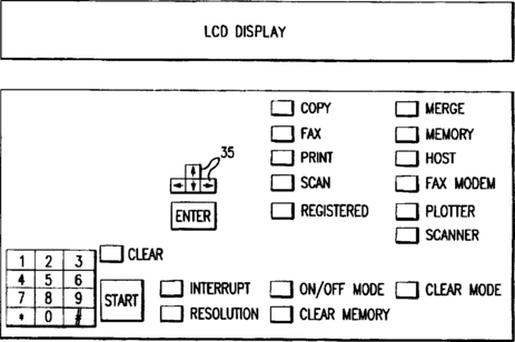
The printer of this machine may be an electrophotographic type (laser or LED), an inkjet, or a thermal transfer type. The scanner may be either a CCD or a CIS type. The scanner or printer may function separately or work together to provide a copy function. The scanner and printer are used with a fax/telephone processor to provide the fax function. Selection of the individual functions is made through a control panel, with an LCD to provide status information as shown in Figure 1.6.
A block diagram of the primary electronic components of this MFP is shown in Figure 1.7. A system bus connects all modules of the machine. A CPU, while servicing multiple tasks, monitors the state of the peripheral. A DRAM and an EEPROM are provided, and a ROM module includes initial values, default values, and firmware. The last may include instructions to handle popular printer commands from various software. An interface controller (1) is coupled to the control panel, and the interface controller (2) is coupled to a host computer.

An interface controller (3), which includes a DRAM, is coupled to the fax/telephone processor. The latter has a module, which distinguishes the incoming information as either voice or fax data and automatically switches the system to the appropriate mode, while notifying the CPU. The fax/telephone processor is coupled to a telephone handset to handle voice information. Interface controller (3) is preferably coupled to an answering unit.
A direct memory access (DMA) controller is also provided. The printer interface is coupled to the printing elements to create the desired output image. A scanner interface couples with the CCD or CIS element so that scanned digital images can be obtained. A system controller connects with the scanner interface and the printer interface through the buses shown in the diagram to allow input-output related functions such as copying. To copy, another bus between the scanner and printer provides an interface, which enables the movement of image data.
An arithmetic logic unit (ALU) is used to merge image data from other sources, as the scan data is sent to the printer interface. In addition, merged data from the scanner can be directed to the DRAM, for temporary storage or for merging with other image data stored there.
The storage interface shown below the system controller in the block diagram is coupled to external storage units, such as hard disks, optical disks, and/or floppy disks. A storage interface associated with merge and route operations may store instructions relative to them. Alternatively, such instructions may be stored in the main ROM.
PRINTERS IN FAX MACHINES
During the 1980s and early 1990s, more than 500 models of fax machines with direct-thermal printers under at least forty different brand names were brought to the market. Although machines with laser and LED printers were available at higher prices, and inkjet printing was developing at a rapid pace, machines with direct-thermal printers introduced G3 fax to the public and to the offices of the world. Faxes were sent and received in offices ranging from the largest to the smallest. There was even considerable success in the personal market, but there fax machines did not become as popular as VCRs or telephones. Nevertheless, by 1991 the total installed base of fax machines worldwide was more than 16 million. The hard copy from the direct-thermal printers was “person-readable,” but there were some deficiencies in it, which had ominous implications for the future.
Since 1995, twenty-five models of fax machines (some of them MFPs) with direct-thermal printers have been introduced to the market under six brand names. Seven of these models were offered by Brother and ten by Sharp. Since then, three of the models offered by Brother and four of the models offered by Sharp have been discontinued. The ones that have remained on the market are very low-priced units, which could be used as MFPs for PCs by adding separate kits, or modems and software. They are targeted to the discount market with the assumption that some potential customers will be satisfied with printed copies on thermal paper.
THERMAL PAPER PRINTING
In general, thermal papers consist of a recording layer on a paper substrate. A variety of chemistries are used to produce images in the heat-sensitive layer. Generally, they include a dye that changes color or “develops” when heat is applied. Images are formed in the heat-sensitive layer by using a printhead in which a matrix of point sources of heat are turned “on” and “off” as the thermal paper moves past it.
Thermal paper offered for use in fax machines (known as “fax paper,” to distinguish it from better quality thermal paper used in plotters and other hard-copy applications) has generally been made as inexpensively as possible to compete in a mass market. A thin paper substrate formed from mechanical pulps is used with as little inexpensive chemistry as possible in the heat-sensitive recording layer. Typically, the paper substrate is not sized or calendered and will have voids in its surface and paper fibers that protrude into the heat-sensitive layer. Fax papers also have no topcoat, a feature found in more expensive, higher quality thermal papers.
The image quality or definition obtained on “fax paper” is generally poor for various reasons. For example, portions of the image are lost where the heat-sensitive recording layer is disrupted by paper fibers protruding from the paper substrate, or where the recording layer has voids or depressions due either to thinness or to underlying voids in the paper substrate. Additionally, coarse surfaces may interfere with heat transfer from the printhead.
Border areas of fax paper images often are irregular and extend beyond the image presented to the thermal printhead. This problem, which is known as “blooming,” comes about because of heat flow into the heat-sensitive recording layer beyond the borders of the image presented by the heat point sources in the printhead. The images produced with fax paper thus are inferior to those obtained with press or laser printing, in which the printed images are sharply defined and correspond precisely to the images intended to be produced.
In addition to the undesirable blooming and limited image definition of fax paper, it is vulnerable to scuffing, erasures, and the development of nonimage areas upon exposure to organic solvents, water, oil, plasticizers, and other materials. Another problem with fax paper arises from fingerprints of the person handling the paper. Also, over time the quality of the copy can degrade because of external heat or light. Thus, it may deteriorate in storage. It also curls, making it difficult to file, so many offices make plain-paper copies of the fax paper copies at additional expense.
Although the sale of fax machines with direct-thermal printers has declined sharply, there is still a considerable demand for thermal fax paper to use in the large installed base of such machines. Efforts have been made to improve this paper, and today it is offered in various grades. A premium grade with standard, high, and ultrahigh sensitivities is available. It also can be had with a recycled paper substrate at a lower price. However, whatever improvements have been made have come too late to slow the move to plain paper printing in multifunction peripherals for personal computers.
THERMAL TRANSFER PRINTERS
Thermal transfer printers are discussed here because of their relationship in technology to direct thermal printers. In general the same printheads are employed, but an ink sheet is fed between the printhead and the paper. The latter is plain paper (ordinary cut-sheet bond) instead of thermal paper. As shown in Figure 1.8, the ink sheet (1) wound on a core (2) is unwound and directed between the thermal head (3) and a platen roller (4) via a tension roller (6) and is taken up by a take-up shaft (8) via a further tension roller (7). The recording paper (5) is directed between the thermal head (3) and the platen roller (4) so as to be superposed under the ink sheet (1). The recording by heat transfer is effected between ink sheet (1) and recording paper (5) as they are conveyed between the thermal head (3) and the platen roller (4).

In October 1988, Chibara Iwasaki of Minolta Camera Company, Osaka, Japan, filed there for a patent covering a fax machine that performed both direct-thermal printing and thermal-transfer printing. In August 1990, U.S. Patent #4,949,097 was granted for this invention. In this patent it was stated that it related to a thermal printer changeable between a thermal transfer printing mode, in which printing is effected by transferring ink from an ink ribbon onto plain paper, and a thermosensible printing mode in which printing is effected on thermal-sensitive paper without using the ink ribbon. It was claimed that the thermosensible mode was provided so that it could be used in testing on inexpensive fax paper, before the final copy was made using the expensive ink ribbon. Surprisingly, the advantage of printing on plain paper was not mentioned in the patent. In the machine of this invention, the ink ribbon was in a cassette similar to that shown in Figure 1.9. When it was installed in the machine, the thermal transfer mode was activated. When the cassette was removed from the machine, it operated in the direct-thermal mode.

Apparently, Minolta did not bring such a fax machine to the market, but a few other manufacturers did so. These included Canon with its first such model in October 1988 (the same month in which Minolta’s inventor filed in Japan for a patent) and its second model in March 1989. Their first model listed at about $3,000 and the second at about $4,500 in the U.S. market. Later thermal/thermal transfer models were introduced by Savin, Nitsuko, and Toshiba. The lowest priced one was by Savin at about $1,000 list.
In January 1989, the Nippon Electric Company (NEC-Japan) introduced an expensive thermal transfer model (listing at about $7,000) with no direct thermal printing capability. (A model introduced by Canon in February 1991 brought the list down to about $1,000.) From September 1988, inventors at Canon filed applications for patents for inventions to conserve the ink ribbon, which was exhausted when the roll was fed past the printhead. It was realized early that the expense of the ink ribbon would render thermal transfer printing noncompetitive in operating cost with other printing methods. Some of the Canon inventions showed the ink ribbon as in Figure 1.8, while others showed cassettes similar to that of Figure 1.9.
PRINTERS IN MFPs
A publication of the Buyers Laboratory, Inc., of Hackensack, New Jersey, in the winter of 1998 gave the specifications of 200 multifunctional machines under 28 brand names on the market at that time. They contained the following types of printers: 131 lasers, 30 inkjets, 16 LEDs, 15 thermal transfers, 2 vacuum fluorescents, 3 direct-thermals, and 2 without a printer. Four low-cost MFPs with direct-thermal printers introduced by Sharp in 1997 were not included. Of the 200 models, there was also one with no data on its printer.
Of the eleven models of MFPs with thermal transfer printers, five were offered by Brother, three each by Panasonic and Sharp, and one by Muratec. Three of the Brother models were introduced in 1997, one in 1995, and one in 1994. All three of the Panasonic models were introduced in 1997. One of the Sharp models was introduced in 1996 and two in 1997, both of which were duplicates sold under two different model numbers. The Muratec unit was first marketed in 1994. None of these models has been discontinued. Suggested retail prices ranged from $550 to $900, with street prices as low as $300.
In August 1998, Brother introduced three new thermal-transfer machines at street prices not much above those of the direct-thermal machines it offered earlier. The Intellifax 770 featured a 14.4 kc modem, 20 pages of memory, and a 100-sheet paper cassette.
Targeted at the SOHO market, its street price was $229. To make it a functional MFP, it was necessary to add to it what Brother called its “Missing Link” PC-fax kit. Using the same engine as the preceding machine, Brother fielded two additional models, which they labeled as fully functional MFPs—their MFC-970MC and their MFC-1970MC. The former offered 200 × 400 dpi printing, 400 × 400 dpi scanning, PC-fax capabilities, and a 15-minute answering machine. All of this for a street price of $279. The latter offered all of the features of the MFC-970MC. In addition it had a 200-sheet paper cassette, 50 pages of memory, and a 30-minute answering machine. The street price of this model was around $299. These units appeared to be in direct competition with the Sharp direct thermal machines mentioned previously. They offered plain paper printing in the same price range.
PLAIN PAPER MONOCHROME PRINTING
The printing methods used in MFPs are the same as those that have been used in fax machines. Direct thermal and thermal transfer have already been discussed. Their application in MFPs is limited to the lowest priced machines aimed at the SOHO market and are channeled through discount store outlets. Neither of these methods is useful in color printing. As indicated on page 15, the principal methods employed in MFPs are laser and inkjet printing. LEDs are rather limited in their usage. Today their technology rests largely with one manufacturer of LED engines. Vacuum fluorescent printing was used in only two models mentioned in the Buyers Laboratory compilation. Both were introduced by Lanier early in 1996 at a fairly high price for low-volume users, and they have not been followed by other models. This method is somewhat similar to the LED method except fluorescent lamps are used instead of light-emitting diodes to illuminate the drum of the printer.
Aside from various ways of judging print quality on hard copy, printers are rated relative to their speed of printing in pages per minute (ppm) and their resolution in dots per inch (dpi).
ELECTROPHOTOGRAPHIC PRINTING
In this method a photoreceptor is illuminated by a signal-controlled source, from which the printers derive their names. The one in which the photoreceptor is illuminated by a light beam from a laser is called a laser beam printer (LBP). The one where the illumination is provided by light-emitting diodes (LEDs) is an LED printer. Illumination provided by vacuum fluorescent lamps produces a printer by that name. The light source places a latent image onto the photoreceptor to which toner is applied to place print on paper (hard copy). The photoreceptor is usually shaped as a tube, called a drum. It may also be in the form of a flexible film loop, called a belt. The drum generally consists of an aluminum tube surrounded by three layers. The outer layer, where the latent image is formed, is an organic photoconductor (OPC), from which the name OPC drum is derived. This layer provides charge transfer. Moving inward, the next layer provides charge generation and the layer next to the aluminum tube is for blocking.
THE LASER BEAM PRINTER
In the operation of a laser beam printer (LBP), the OPC rotates in the direction indicated by the arrow A as shown in Figure 1.10. It is uniformly charged to a negative potential by a primary charger (6—a corona wire as shown here, or a charge roller) and is exposed to a laser beam (8) to form an electrostatic latent image upon it.
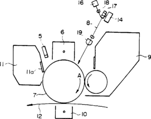
The laser beam (8) is emitted from a laser unit, which includes a laser diode and a collimator lens, in a beam modulated in accordance with an electrical signal. This beam is swept across the drum (7) by the rotational polygon mirror (17). A recording line is made by each face of the mirror. A focusing lens keeps the spot in focus along the recording line. The drum rotates the equivalent of one recording line for each sweep of each mirror face. A motor (14) drives the polygon mirror (17). The lens groups (18) and (19) correct for tilt of the polygon mirror and imaging lenses.
The latent image formed on the OPC drum is reverse-developed by a section (9) containing toner. The developed image is transferred onto paper as it moves past a transfer charge (10). From there the paper is passed between two fusing rollers (not shown) to affix the developed image to the paper to form a hard copy. After image transfer, the OPC drum is cleaned by a section (11) containing a blade (11a) contacting the surface of the drum to remove residual developer. Then the residual electric charge is removed by a preexposure lamp (5) to prepare the drum for another cycle. The developer and the toner components are separated in some designs, but in a popular form these elements are placed together in replaceable cartridges.
Ricoh and Canon introduced fax machines with laser printers in the early 1980s. Canon’s first model was its L910, brought out in 1985 at about $6,500. Large corporate users have preferred fax machines with laser printers because of their speed and quality of hard copy. A top Xerox model 265 Document Center (classed by Buyers Lab as an MFP), which is only a copier with an optional function as a printer, has a print speed of 65 ppm at 600 × 600 dpi. At a price of $39,750, it would appeal only to very large corporate users. Coming down in price to $13,495, there is Ricoh’s Aficio 401, which Lanier markets as its model 5040 MFD and Savin markets as its 9940 DPC (all introduced in 1997). It is capable of 40 ppm at a resolution of 400 dpi. It is also a digital copier with separate printer and scanner functions. Neither of these machines has regular or computer fax functions. In 1998 Canon still had on the market its GP30F, introduced in 1995, another copier but with optional fax, computer fax, printer, and scanner functions. It is capable of 30 ppm at 400 × 400 dpi. Its price is just below $7,000.
In the price range of $1,500 to $4,000, there are many models of MFPs with laser printers capable of doing 10 ppm at 600 × 600 dpi. Practically all of them include the fax function. They appeal to medium-size offices as well as some corporate ones. Aimed at the SOHO market, Brother introduced in 1998 an MFD, its model MFCP2000, capable of 10 ppm at 600 dpi. It supports scanning, printing, and copying for a PC, but does not have the fax function. Its street price is $449.
INKJET PRINTERS
An inkjet printer forms an image by printing a pattern of individual dots at particular locations of an array defined for the printing medium. The locations are conveniently visualized as being small dots in a rectilinear array. Thus, the printing operation can be viewed as the filling of pattern locations with dots of ink.
Inkjet printers include a movable carriage that supports one or more printheads with nozzles ejecting very small drops of ink onto the print medium. The carriage traverses the surface of the print medium, while the printhead nozzles are controlled to eject drops of ink at appropriate times under the command of a microprocessor or controller timing the application of the ink drops to correspond to the pattern of pixels of the image being printed.
A typical printhead consists of a silicon substrate and connections to the substrate. It uses liquid ink (dissolved colorants or pigments dispersed in a solvent). It has an array of precisely formed nozzles attached to the substrate incorporating an array of firing chambers, which receive liquid ink from the ink reservoir. Each chamber has a thin-film resistor, known as a firing chamber resistor, located opposite the nozzles, so that ink can collect between it and the nozzle. The firing of the ink droplets is typically under the control of signals that are conveyed by electrical traces from a microprocessor to the resistor elements. When electric pulses heat the inkjet firing chamber resistor, a small portion of ink next to it vaporizes and ejects as a drop of ink from the printhead. The nozzles are arranged as for a dot matrix pattern. Sequencing the operation of each nozzle causes characters or images to be printed upon the paper as the printhead moves past it. The ink cartridge is moved repeatedly across the width of the medium to be printed upon. At each of a designated number of increments of this movement across the medium, each of the nozzles is caused to either eject ink or refrain from ejecting ink according to the program output of the controlling microprocessor. Each completed movement across the medium can print a swath approximately as wide as the number of nozzles arranged in a column of the ink cartridge multiplied by the distance between the nozzles’ centers. After each completed movement or swath, the medium is moved forward the width of the swath, and the ink cartridge begins the next swath. By proper selection and timing of the signals, the desired print is obtained on the paper.
Hewlett-Packard uses the method just described for ejecting ink droplets onto the paper. Canon indirectly heats the ink to form a bubble of air that forces the ink through the nozzle (see Chapter 3). In its color printers, Brother International uses an electrostatic method (see Chapter 10).
THE MECHANISM AND THE CARTRIDGES
A basic inkjet recording mechanism is shown in Figure 1.11. It is equipped with an ink cartridge having a recording head (2) and an ink container (3). This cartridge (1) is placed detachably on a carriage (4), which is supported and guided for movement along a guide rail (5). It is reciprocated in the direction of the double-headed arrows (P) through a timing belt (7) by a carriage motor. The recording material (8) in the form of a sheet of paper is fed in the direction indicated by the arrow (F) at a predetermined timing, with a predetermined pitch, along a path by a pair of feeding rollers (10) driven by a feeding motor (9) and a pair of holding rollers.

While the recording paper is supported flat at a position facing the recording head, the carriage is moved so that the recording operation is performed during the main scan in the direction P. Upon completion of one line of recording, the paper (F) is stepped at a predetermined pitch corresponding to the width of the recording line in the direction (F). Then, recording is performed for the next line. The ink cartridge, including the recording head and the ink container, is replaceable when exhausted.
Figure 1.12 is a partly broken perspective view illustrating the structure of the ink cartridge (1). The inside of the cartridge is divided into a recording head (2) and an ink container (3). Inside the container, an ink absorbing material (6) retains the ink. This ink is supplied to the recording head through a conduit (7) and is ejected through outlets in the head. An air vent (8) provides ventilation for the container.

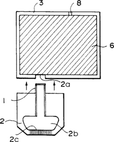
In this method, the recording head utilizes thermal energy to eject the ink and is provided with electrothermal transducers (heat generation resistors). The ink is ejected from the head using the pressure change resulting from the expansion and contraction of bubbles generated by film boiling, which produces ink ejection energy. The electrothermal transducers are driven by image signals. An ink cartridge in which the recording head portion and the ink-containing portion are separable from each other is shown in Figure 1.13. In this structure, an ink-supplying portion (1) is projected from the recording head (2), instead of from the ink conduit shown in Figure 1.12, and is inserted into the ink supply port (2a). Along the walls of liquid passage between the chamber (2b) and the ejection outlets (2c), the heat generating resistors provide ejection energy.
During the 1980s, Hewlett-Packard and Canon were granted the most patents relating to inkjet technology. However, the Matsushita Electric Company introduced the first fax machine with a monochrome inkjet printer in July 1990. Under the Panafax brand name, it was their model UF-300 priced at about $2,500. Hewlett-Packard followed in June 1991, with its first such model at about $2,100. Canon’s first model did not appear until July 1992, at about $1,350. By 1996, Canon had introduced twelve models, Hewlett-Packard had brought out eleven models, and Panasonic had marketed eight models of fax machines with monochrome inkjet printers.
COLOR INKJET PRINTERS IN MFPs
Most inkjet printers that turn out color copy employ either one print cartridge, which is interchangeable for a black or color print, or two or more print cartridges mounted in the printer carriage to produce black print or a full spectrum of colors. In a printer with four cartridges, each print cartridge contains a different color of ink, with the commonly used base colors of black, cyan, magenta, and yellow. In a printer with two cartridges, one cartridge usually contains black ink with the other cartridge having three compartments containing the base colors of cyan, magenta, and yellow inks. The base colors are produced on paper by depositing a drop of the required color onto a dot location. Secondary or shaded colors are formed by depositing multiple drops of different base color inks onto the same dot location, with the overprinting of two or more base colors to produce the secondary colors.
Of the thirty models of MFPs with inkjet printers mentioned on page 11, twenty were capable of color printing and eight of these models were capable of color scanning as well as color printing. A strong demand for color printing in MFPs is indicated, with inkjet printing dominating the market. No MFPs with color laser printers were listed in the Buyers Laboratory compilation. Laser printers are capable of excellent color printing. However, their mechanisms are more complex and are so expensive that they have not been competitive with color inkjet printing technology.
Single-function color laser/LED printers have been selling in the price range of $4,000 to $5,000, while single-function color inkjet printers have been selling below $500. In 1996, 56,000 color laser/LED printers were reported to have been sold, in contrast with 10 million color inkjet printers sold in the same period. Single-function color laser/LED printers are used in large office applications. Even so, at this time they are not found in MFPs for PCs.
SCANNERS IN MFPs
In MFPs, one finds the same basic photosensors in scanners as have been used in fax machines. They are photodiodes in the form of charged coupled devices (CCDs) or contact image sensors (CISs). They are arranged to cover the width of the image to be scanned. Monochrome image sensor arrays typically consist of a linear array of photodiodes, which raster scan an image-bearing document and convert the microscopic image area viewed by each photodiode to image signal charges. Following integration, the image signals are amplified and transferred to a common output line or bus by successive actuation of multiplexing transistors. As analog signals they are fed to an image processor, where they are subjected to shading correction and contrast control. Then they are converted to digital form.
CCD sensor chips are arranged with 1,728 photosensors in a straight line. However, they are physically small compared to a paper document. So optical reduction is required to fit the image to them. As shown in Figure 1.14, the necessary optics are in the form of lenses and mirrors, which are required to reduce the overall size of the scanner unit. Most MFPs do not contain flatbed scanners, so a stepper motor moves the page over the scanner. The scanning line position is determined by that part of the page being focused on the CCD chip. The area of the page being scanned is usually illuminated by light-emitting diodes (LEDs).

A basic contact image sensor (CIS) is arranged as shown in Figure 1.15. A sensor base plate (2) of a contact-type sensor is fixed to the mounting surface (4a) of frame (4). A document (7) is conveyed as shown by the arrow and pressed against the sensor base plate (2) by a rotating platen roller (1). Light passing through the window (6) is irradiated to the document and the CIS reads the image. In actual practice, a small window is provided in each sensor element through which an LED illuminates the page. The light is reflected back from the page to the sensor. A thin transparent coating keeps the page a small distance away from the sensors.

In another arrangement, a narrow bar containing a fiberoptic rod lens is mounted between the document and the light sensitive sensors as shown in Figure 1.16. The page is illuminated by an LED light source. Although this arrangement is called a contact image sensor, the document is not in actual contact with the sensor. However, it is less than 2 centimeters away as compared with 30 centimeters in a typical CCD scanner.

Color Scanners
Color scanners also employ either CCD or CIS sensors, but they must be arranged in arrays with color filters to separate the primary colors. A typical color scanner consists of three CCD arrays, each separately covered by green, blue, and red filters. The document to be scanned is illuminated by a white fluorescent lamp with peak intensity of green, blue, and red light. Light is reflected by mirrors and reduced optically by a lens to form an image fitting the CCD arrays. Color scanning of a single scan line is completed as the document advances from green and passes through blue and red starting positions. The scanner retains a certain number of scan lines from the green image and a certain number from the blue image. When a red image is scanned, all of the color data of the same line is merged to form a full color image.
Early in 1998, at least eight models of MFPs for PCs incorporated color scanners as well as color printers. They were two models of the MFC-7000 series by Brother, the Multipass C5000 by Canon, three models in their 600 series by Hewlett-Packard, the UF-344 Panafax, and the Xerox Home Centre. Since then Sharp has launched a full color MFP, their UX-2700CM.
SERVICING CONSIDERATIONS
In the United States, the servicing and repair of fax machines did not develop in the same way as that of TV sets, VCRs, camcorders, and other electronic home instruments. It developed along the lines of office machine products. To service TVs, VCRs, etc., one did not have to be an authorized dealer of the products, so many independent service personnel entered that business with little investment and their businesses expanded rapidly when VCRs came onto the scene and created a large demand for service and repair.
Modern facsimile is almost entirely a Japanese development. From the beginning the Japanese companies saw to it that the service and repair of fax machines was to be provided only by authorized dealers. One of the conditions for becoming an authorized dealer was to purchase a certain quantity of their products. This requirement limited the number of repair personnel. Except for rare cases, service and repair were provided at authorized dealers or direct factory service facilities. This approach required service personnel, but they had to be authorized dealers, employees of authorized dealers, or employees of the manufacturer or sales outlet. They were usually given training at the service facilities of the manufacturer.
Since the early 1990s, it has been easier to purchase service manuals for most fax machines without being an authorized dealer. Also, it has become possible to purchase repair parts directly from manufacturers or secondary sales outlets. This has opened up possibilities for others than authorized dealers. In this regard there are at least two significant areas.
An area that offers considerable potential is the combination of MFP servicing with PC service and repair. In general, PC servicing has been a field by itself. The popularity of PCs has made them a consumer product. Manufacturers have not demanded that they be serviced by authorized dealers or that they be returned to them. They have offered courses and examinations to qualifying independent service personnel. Schools that offer vocational training as well as those that offer correspondence courses are very active. PC service personnel can do well by adding training in MFP, printer, and scanner service and repair. Most MFPs consist of the engines of single-function printers and scanners combined with the components of the fax function. Therefore, by learning MFP service and repair, one can also acquire capability to deal with the problems of all peripherals that surround the PC, whether they are combined or separate.
Another of these is with the remanufacturers of process and toner cartridges for laser printers and ink cartridges for inkjet printers. This field has undergone amazing expansion during the past few years. There are now about 10,000 remanufacturers of laser cartridges and their business is at a total level of about $3 billion. It is estimated that they have about one-third of the laser cartridge replacement market; the original manufacturers of the laser printers have the remainder. This activity is a form of servicing copiers, printers, and laser fax machines, as well as MFPs containing such printers. Some of these remanufacturers have combined equipment servicing with their primary activity, and others are interested in doing so. Also, since remanufacturing of cartridges is often done by a two- or three-person activity, the servicing of MFP equipment can be readily combined with it. The remanufacture of ink cartridges is still in its infancy, with only about 5% of the demand being filled by other than the original printer maker. It is easier to do than laser cartridge remanufacture and could appeal more to those primarily interested in equipment servicing.
Even if one does not wish to remanufacture cartridges, it is well to know what is available from remanufacturers or their sales outlets. For those who may wish to do remanufacturing of cartridges, considerable information is given in Chapter 10. Other consumables, such as various types of paper that produce better hard-copy quality, are covered in that chapter. The cost of hard-copy supplies for fax machines and MFPs exceeds the initial cost of the equipment in a relatively short time. The sales opportunities open to servicemen in these areas can be very important. So they should be abreast of the latest developments in such products.