
Chapter 8 Optical Storage Media
Conventional magnetic data carriers in the form of hard disks or removable disks are traditionally used in computers as secondary storage media. These offer low average access time and provide enough capacity for general computer data at an acceptable price. However, audio and video data, even in compressed form, place heavy demands on available storage capacity. The storage cost for continuous media is thus substantial unless other data carriers are used.
Optical storage media offer higher storage density at a lower cost. The audio compact disc (CD) has been commercially successful in the consumer electronics industry as the successor to long-playing records (LPs) and is now a mass-produced product. Due to the large storage capacity of this technology, the computer industry has benefited from its development, especially when audio and video data are stored digitally in the computer. This technology is thus the main catalyst for the development of multimedia technology in computers. Other examples of external devices that can be used for multimedia systems include video recorders and DAT (Digital Audio Tape) recorders.
However, even the aforementioned mass storage media are not adequate to meet the data rates and especially storage requirements implied by current quality standards for multiple applications and data. This has led to the development of new media with many times the storage density of CDs or DAT tapes. The most important one, designated Digital Versatile Disc (DVD), is based on CD-ROM technology and was standardized by an alliance of multimedia manufacturers.
Actually integrating multimedia into systems that do not offer random access (e.g. magnetic mass storage such as DATs) is possible in some cases, though not easy [HS91, RSSS90, SHRS90]. This chapter thus focuses primarily on optical storage. Other data carriers are not considered here since most either do not have special properties with respect to integrated multimedia systems, or will be considered as components of a media server.
In the following, we explain the basics of optical storage media, followed by a brief discussion of analog and Write Once Read Many (WORM) systems. CD-ROM and CD-ROM/XA are explained based on CD-DA. Various other developments that pertain to multimedia include CD-I and the Photo CD, which are covered briefly. In addition to read only developments of the CD, the subsequently introduced CD-WO and CD-MO have been available for some time. This chapter concludes by comparing these CD technologies with one another and mentioning possible further developments.
8.1 History of Optical Storage
The video disc was first described in 1973 in the form of the Video Long Play (VLP). So far the video disc as a read-only medium has not been commercially successful although a large number of different write-once optical discs of different sizes and formats have been marketed. Most developments are based on analog technology, which can satisfy the highest quality standards at an acceptable cost.
About ten years later, at the end of 1982, the Compact Disc Digital Audio (CD-DA) was introduced. This optical disc digitally stores audio data in high-quality stereo. The CD-DA specification, drawn up by N.V. Philips and the Sony Corporation, was summarized in the so-called Red Book [Phi82]. All subsequent CD formats are based on this description. In the first five years after the introduction of the CD-DA, about 30 million CD-DA players and more than 450 million CD-DA discs were sold [BW90b].
The extension of the Compact Disc to storage of computer data was announced by N.V. Phillips and Sony Corporation in 1983 and introduced to the public for the first time in November 1985. This Compact Disc Read Only Memory (CD-ROM) is described in the Yellow Book [Phi85], which later led to the ECMA-119 standard [ECM88]. This standard specifies the physical format of a compact disc. The logical format is specified by the ISO 9660 standard, which is based on an industry proposal (High Sierra Proposal) and allows access using filenames and a directory.
In 1986, N.V. Philips and the Sony Corporation announced Compact Disc Interactive (CD-I). CD-I is described in the Green Book [Phi88], which includes, in addition to the CD technology, a complete system description. In 1987, Digital Video Interactive (DVI) was presented publicly. The primary emphasis in DVI is on algorithms for compression and decompression of audio and video data stored on a CD-ROM.
In 1988, the Compact Disc Read Only Memory Extended Architecture (CD-ROM/XA) was announced. N.V. Philips, Sony Corporation, and Microsoft produced a specification of digital optical data carriers for multiple media, which was published in 1989 at the CD-ROM conference in Anaheim, California [Phi89].
Since the beginning of 1990, we have seen the development of the Compact Disc Write Once (CD-WO) and the rewritable Compact Disc Magneto Optical (CD-MO), both specified in the Orange Book [Phi91]. Additionally, since the beginning of 1995 there has been the rewritable and erasable CD-RW (Compact Disc Read Write), also specified in the Orange Book [Phi91] (Part 3).
At the beginning of 1996, efforts to develop compact discs with higher storage densities began. This was initially carried out in a proprietary fashion by individual firms. At the end of 1996, the firms joined to form the DVD Consortium. The first DVD specifications became available by the middle of 1997, and the first devices by the end of 1997.
8.2 Basic Technology
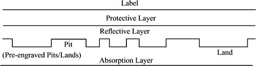
In optical storage media, the underlying principle is that information is represented by using the intensity of laser light reflected during reading. A laser beam having a wave length of about 780nm can be focused to a resolution of approximately 1 μm. In a polycarbonate substrate layer, there are depressions, called pits, corresponding to the data to be encoded. The areas between the pits are called lands. Figure 8-1 shows a sectional view through an optical disc, running lengthwise along a data track. The pits and lands are represented schematically in the middle of the figure.
Figure 8-1 Sectional view of an optical disc along the data track. Schematic representation of the layers (top), the “lands” and the “pits” (middle), and the signal waveform (bottom).

The substrate layer is smooth and coated with a thin, reflective layer. The laser beam is focused at the height of the reflective layer from the substrate level. The reflected beam thus has a strong intensity at the lands. The pits have a depth of 0.12 μm from the substrate surface. Laser light hitting pits will be lightly scattered, that is, it will be reflected with weaker intensity. The signal waveform shown schematically at the bottom of Figure 8-1 represents the intensity of the reflected laser light; the horizontal line represents a threshold value. The laser in the figure is currently sampling a land.
According to Figure 8-1, a Compact Disc (CD) consists of:
• the label,
• the protective layer,
• the reflective layer and
• the substrate.
Figure 8-2 Data on a CD as an example of an optical disc. Track with “lands” and “pits.”

An optical disc consists of a sequential arrangement of pits and lands within a track. The pits and lands represent data on the surface. Figure 8-2 shows a greatly enlarged detail of such a structure.
In contrast to floppy disks and other conventional secondary storage media, all the information on an optical disc is placed on one track. The stored information can thus be played back at a continuous data rate, which has particular advantages for continuous data streams such as audio and video data.
A track is in the form of a spiral. In the case of a CD, the spacing between adjacent coils of the spiral—the track pitch—is 1.6 μm. The track width of the pits is 0.6 μm, though their lengths can vary. The most important advantage of the CD over magnetic storage media follows from these measurements. Along the length of the data track, 1.66 data bits/μm can be stored, resulting in a storage density of 1,000,000bit/mm2. With the given geometry, this corresponds to 16,000 tracks/inch. In comparison, a floppy disk has only 96 tracks/inch.
While magnetization can decrease over time and, for example in the case of tapes, crosstalk can occur, optical storage media are not subject to such effects. These media are thus very well suited for long-term storage. Only a decomposition or change of the material can cause irreparable damage. However, according to current knowledge, such effects will not occur in the foreseeable future.
The light source of the laser can be positioned at a distance of approximately 1 mm from the disk surface and thus does not touch the disk directly, or float on an air cushion, as is the case with magnetic hard disks. This reduces wear and tear on the components used and increases the life of the device.
8.3 Video Discs and Other WORMs
Video discs in the form of LaserVision are used for the reproduction of motion picture and audio data. The data are stored on the disc in an analog-coded format, and the sound and picture quality are excellent. LaserVision discs have a diameter of approximately 30cm and store approximately 2.6Gbytes.
Following the naming of the well known long play (LP) for audio information, the video disc was originally called Video Long Play. It was first described in 1973 in the Philips Technical Review [Phi73].
Motion pictures are frequency-modulated on the video disc, and the audio signal is mixed with the modulated video signal. Figure 8-3 shows the principle used to record data. The important information of the mixed audio-video signal is the temporal sequence of the zero transitions. Each zero transition corresponds to a change between a pit and a land on the disc. Such a change can occur at any time, and is written to the disc in a nonquantized form, that is, the pit length is not quantized. This method is thus time-continuous and can be characterized as analog.
Figure 8-3 Sectional view of a video disc. Time-continuous discrete value coding.

The video disc was conceived as a Read Only Memory. Since then, many different write-once optical storage systems have come out, known as Write Once Read Many (WORM). An example is the Interactive Video Disc, which operates at Constant Angular Velocity (CAV). On each side, up to 36 minutes of audio and video data at 30 frames per second can be stored and played back. Alternatively, approximately 54,000 studio quality still images can be stored per side.
In 1992, there were already many write-once storage media with capacities between 600 Mbytes and about 8 Gbytes. These discs have diameters between 3.5 and 14 inches. The primary advantage of a WORM over rewritable mass storage is security against alteration. In order to further increase capacity, there are so-called jukeboxes, which can yield capacities of more than 20 Gbytes by using multiple discs.
Besides the large number of incompatible formats, software support is lacking in most systems. Computer integration is only available for a few selected systems.
WORMs have the following special properties:
• The term media overflow refers to problems that can occur when a WORM disc is almost full. Firstly, a check must be performed to see if data to be stored can fit on the WORM disc. Moreover, it must be determined if the data can or should be written on different physical discs, and if so, at what point in time to write to the new disc. This is particularly important for continuous media, since these data streams can only be interrupted at certain points.
• Packaging refers to problems stemming from the fixed block structure of WORMs. It is only possible to write records of one given size. For example, if the block size is 2,048 bytes and only one byte is written, then 2,047 bytes will be recorded without any information content.
• Revision refers to the problem of subsequently marking areas as invalid. For example, if a document is changed, the areas that are no longer valid must be marked as such, so that programs can always transparently access the current version. Such changes can result in a document being distributed over multiple WORM discs. Yet this must not disturb playback of continuous media streams.
8.4 Compact Disc Digital Audio
The Compact Disc Digital Audio (CD-DA) was developed jointly by N.V. Philips and the Sony Corporation for storing audio data. The basic technology of the CD-DA was developed by N.V. Philips [MGC82, DG82, HS82, HTV82].
8.4.1 Technical Basics
CDs have a diameter of 12cm and are played at a Constant Linear Velocity (CLV). The number of rotations per time unit thus depends on the radius of the data currently being sampled. The spiral-shaped CD track has approximately 20,000 windings; in comparison, an LP has only approximately 850 windings.
Information is stored according to the principle depicted in Figure 8-1 and Figure 8-4, whereby the length of the pits is always a multiple of 0.3 μm. A change from pit to land or from land to pit corresponds to the coding of a 1 in the data stream. If there is no change, a 0 is coded. In Figure 8-4, the data stream shown below corresponds to the coded data.
Figure 8-4 “Pits” and “lands.” Discrete time, discrete value storage.

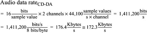
8.4.1.1 Audio Data Rate
The audio data rate can easily be derived from the given sampling rate of 44,100Hz and the 16-bit linear quantization. The stereo audio signal is pulse code modulated, and the data rate is as follows:
Analog long-playing records and casette tapes have a signal-to-noise ratio of approximately 50 to 60dB. The quality of the CD-DA is substantially higher. As a rule of thumb, one can assume 6dB per bit used during the sampling process. Given 16-bit linear sampling:
![]()
The signal-to-noise ratio is exactly 98dB.
8.4.1.2 Capacity
The play time of a CD-DA is at least 74 minutes. Using this value, the capacity of a CD-DA can easily be determined. The capacity given below applies only to storage used for audio data, without, for example, taking into account data used for error correction:

8.4.2 Eight-to-Fourteen Modulation
Each change from pit to land or land to pit corresponds to a channel bit of 1; if no change takes place, the channel bit is a 0.
Pits and lands may not follow each other too closely on a CD, since the resolution of the laser would not suffice to read direct pit-land-pit-land-pit… sequences (i.e., 11111 sequences) correctly. Therefore, it was agreed that at least two lands and two pits must always occur consecutively. Between every two 1s as channel bits, there will thus be at least two 0s.
On the other hand, pits and longs cannot be too long, otherwise a phase-correct synchronization signal (clock) cannot be derived. The maximum length of pits and lands was thus limited such that there can be at most ten consecutive 0s as channel bits.
For these reasons, the bits written on a CD-DA in the form of pits and lands do not correspond directly to the actual information. Before writing, Eight-to-Fourteen Modulation is applied [HS82]. This transformation ensures that the requirements regarding minimum and maximum lengths are met.
Eight-bit words are coded as 14-bit values. Given the minimum and maximum allowed distances, there are 267 valid values, of which 256 are used. The code table includes, for example, the entries shown in Table 8-1.
Table 8-1 Eight-to-Fourteen code table. Two sample entries.

With direct sequencing of modulated bits (14-bit values), it is still possible that the minimum distance of two bits would not be met, or that the maximum distance of ten bits would be exceeded. Three additional bits are inserted between successive modulated symbols to ensure that the required regularity is met. These filler bits are chosen based on the neighboring modulated bits, as illustrated in Figure 8-5.
Figure 8-5 Integration of filler bits. p stands for pit, and l stands for land.

8.4.3 Error Handling
The goal of error handling on a CD-DA is the detection and correction of typical error patterns [HTV82]. An error is usually the result of scratches or dirt. These can usually be characterized as burst errors.
The first level of error handling implements two-stage error correction according to the Reed-Solomon algorithm. For every 24 audio bytes, there are two groups of correction data bytes, each of four bytes. The first group corrects single-byte errors while the second group corrects double-byte errors. The correction bytes also allow detection of additional errors in the sequence, although these cannot be corrected using this approach.
In the second level, real consecutive data bytes are distributed over multiple frames (a frame consists of 588 channel bits, corresponding to 24 audio bytes). The audio data are stored interleaved on the CD-DA. In this way, burst errors will always damage only parts of the data.
Using this technique, an error rate of 10-8 is achieved. Burst errors that span at most seven frames can be detected and corrected exactly. This corresponds to a track length of over 7.7mm. In this case, no additional errors can occur in this area. One can, for example, drill a hole with a diameter of 2mm in a CD-DA and still play the audio data correctly. However, experiments have shown that CD players do not correct all errors according to the given specifications.
The method described above for error correction is known as Cross Interleaved Reed-Solomon Code.
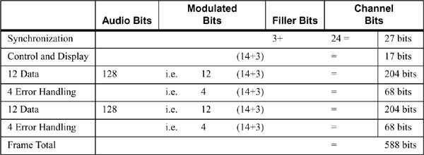
8.4.4 Frames, Tracks, Areas, and Blocks of a CD-DA
Frames consist of audio data, error correction, additional control and display bytes, and a synchronization pattern.
• The audio data are divided into two groups of 12 bytes each. They contain the high and low bytes of the left and right channels.
• Additionally, the error detection and correction bytes as described above are appended to each frame in two groups of four bytes each.
• Each frame has a control and display byte, consisting of eight bits, designated P, Q, R, S, T, U, V, and W (subchannels). Subchannel bits from 98 frames are collected and used together, yielding eight subchannels of 98 bits each, of which 72 bits are used for actual information. Every 98 frames form a block. Unfortunately, sometimes the blocks are also called frames. The P subchannel is used to distinguish a CD-DA with audio data from a CD with other computer data. The Q subchannel is used, for example:
• in the lead-in area to store the directory,
• in the rest of the CD-DA to specify the relative time within a track and the absolute time on the CD-DA.
• The synchronization pattern determines the beginning of each frame. It consists of 12 1s followed by 12 0s as channel bits and three filler bits.
Table 8-2 shows an overview of the components of a frame and its corresponding bits.
Table 8-2 Components of a frame.
Using these data, different data streams with corresponding data rates can be distinguished [MGC82]:
• The audio bit stream (also called the audio data stream) carries 1.4112×106bit/s, counting only the 16-bit quantized sample values.
• The data bit stream includes the audio bit stream as well as the control and display bytes and bytes needed for error handling. The data rate is 1.94×106 bit/s.
• The channel bit stream contains the data bit stream with the Eight-to-Fourteen Modulation and filler and synchronization bits. The data rate is about 4.32×106 bit/s.
Altogether, a CD-DA consists of the following three areas:
• The lead-in area contains the directory of the CD-DA. The beginning of the individual tracks are registered here.
• The program area includes all tracks of the CD-DA; the actual data are stored here.
• At the end of each CD-DA, there is a lead-out area. This is used to help the CD player should it inadvertently read beyond the program area.
The program area of each CD-DA can consist of up to 99 tracks of different lengths. A CD-DA consists of at least one track, whereby a track usually consists of, for example, a song or a movement of a symphony. Random access to the beginning of each track is possible.
According to the Red Book specification, each track can have multiple index points, allowing direct positioning at certain points. Usually only two pre-defined index points (IP), IP0 and IP1, are used. IP0 marks the beginning of each track, and IP1 marks the beginning of the audio data within the track. The area within a track between IP0 and IP1 is called the track pregap. CD-DA discs have a track pregap of two to three seconds per piece.
Besides frames and tracks, another structure, called the block, was established (see Figure 8-6), though it does not have any significance for the CD-DA. In other CD technologies, it is used like a sector. A block contains 98 frames (see further details in Section 8.5.1).
Figure 8-6 Actual data of a CD audio block (sector). Layout according to the Red Book.

8.4.5 Advantages of Digital CD-DA Technology
Errors on a CD-DA can be caused by damage or dirt. For uncompressed audio, the CD-DA is very insensitive to read errors that usually occur. As far as the digital technology, all CD-DAs are identical. An additional advantage is that there is no mechanical wear and tear.
The CD-DA specification as specified in the Red Book serves as the basis of all optical CD storage media. For example, Eight-to-Fourteen Modulation and the Cross Interleaved Reed-Solomon Code are always used. Hence, a fundamental specification was developed that is used in many systems, providing compatibility across the systems. However, the achievable error rate is too high for general computer data, necessitating an extension of the technology in the form of the CD-ROM.
8.5 Compact Disc Read Only Memory
The Compact Disc Read Only Memory (CD-ROM) was conceived as a storage medium for general computer data, in addition to uncompressed audio data [PS86, FE88, Hol88, LR86, OC89]. Further, CD-ROM technology was intended to form the basis for the storage of other media [KSN+87, Wil89]. It was specified by N.V. Philips and the Sony Corporation in the Yellow Book [Phi85] and later accepted as an ECMA standard [ECM88].
CD-ROM tracks are divided into audio (corresponding to CD-DA) and data types. Each track may contain exclusively data of one type. A CD-ROM can contain both types of tracks. In such a mixed mode disc (see Figure 8-13), the data tracks are usually located at the beginning of the CD-ROM, followed by the audio tracks.
8.5.1 Blocks
Since CD-ROMs store general computer data, they require better error correction and higher resolution random access to data units than are specified for CD-DA. A CD-DA has an error rate of 10-8 and allows random access to individual tracks and index points.
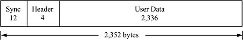
The CD-ROM data unit is called a block1 and has similar properties to the sectors of other media and file systems. A CD-ROM block consists of the 2,352 bytes of a CD-DA block. Thus the de facto CD-DA standard can serve as the basis for the de facto CD-ROM standard.
1 This refers to the physical block; in ISO 9660, there is also the concept of a logical block.
Of the 2,352 bytes of a block, 2,048 bytes (computer data) or 2,336 bytes (audio data) are available for user data. The remaining bytes are used for identification for random access and for another error correction layer that further reduces the error rate.
Figure 8-7 CD-ROM data hierarchy. Audio blocks as on a CD-DA.

Figure 8-7 shows the data hierarchy of a CD-ROM or CD-DA.
Seventy-five blocks per second are played back. Each block consists of 98 frames of 73.5 bytes (588 bits) each.
![]()
8.5.2 Modes
The CD-ROM specification was defined with the goal of storing uncompressed CD-DA data and computer data, as well as serving as the basis for other media. This is achieved by using two CD-ROM modes. An additional mode 0, where all 2,336 user data bytes are set to zero, serves to separate storage areas.
8.5.2.1 CD-ROM Mode 1
CD-ROM mode 1 is used to store computer data, as shown in Figure 8-8. Of the 2,352 total bytes in each block, 2,048 bytes are available for storing information.
Figure 8-8 CD-ROM mode 1 block (sector) layout according to the Yellow Book.

To be more exact, the 2,352 bytes can be broken down into the following groups:
• 12 bytes for synchronization as the start-of-block indicator,
• 4 bytes for the header. This contains an unambiguous block identifier. The first two bytes contain minutes and seconds, respectively; the third byte contains the block number, while the fourth byte identifies the mode,
• 2,048 bytes of user data,
• 4 bytes for error detection,
• 8 unused bytes, and
• 276 bytes for error correction, whereby an error rate of 10-12 can be achieved.
Given a playing time of 74 minutes, a CD-ROM can store 330,000 blocks.
The capacity of a CD-ROM with all blocks in mode 1 can be calculated as follows:

The data rate in mode 1 is:
![]()
8.5.2.2 CD-ROM Mode 2
CD-ROM mode 2 serves as the basis for additional specifications for storage of other media. A block in this mode is shown in Figure 8-9. Of the 2,352 total bytes in each block, 2,336 bytes are available for storing information.
Figure 8-9 CD-ROM mode 2 block (sector) layout according to the Yellow Book.
The synchronization and header are dealt with as in mode 1. The additional error correction is left out.
The capacity of a CD-ROM with all blocks in mode 2 can be calculated as follows:
![]()
The data rate in mode 2 is:
![]()
8.5.3 Logical File Format
It was recognized early on that the specification of blocks in mode 1 as an equivalent to other data carriers’ sectors was not, by itself, sufficient to define a compatible data carrier, since the logical file format and the directory were missing.
A group of industry representatives thus met in Del Webb’s High Sierra Hotel & Casino in Nevada and worked out a proposal that became known as the High Sierra Proposal. This proposal served as the basis for the ISO 9660 standard, which describes the format exactly (see, for example, its application in [KGTM90]).
The ISO 9660 standard defines a directory tree, which includes information about all files. In addition, there is a table that lists all the directories in a compressed form. This so-called path table allows direct access to files at any level. The table is loaded into the computer memory when a CD is mounted. Because a CD-ROM cannot be changed (read only), this method can be performed statically in an efficient fashion. However, most implementations use the actual directory tree.
ISO 9660 reserves the first 16 blocks (sectors 0 through 15) in the first track for the system area, which can be used in a vendor-specific manner. The volume descriptors start at sector 16 (for example, the primary volume descriptor or the supplementary volume descriptor). The most important descriptor is the primary volume descriptor, which includes, among other things, the length of the file system it defines as well as the length of the path table. Additional file systems can be defined using supplementary volume descriptors, which among other things offers flexibility with regard to the character sets allowed for file names.
Each volume descriptor is stored in a 2,048-byte block, and a CD-ROM can contain an arbitrary number of volume descriptions. Repeated copies of individual volume descriptors are usually stored in order to provide increased reliability in the case of a defective CD-ROM. The volume descriptor area ends with a volume descriptor terminator, which is implemented as a special block.
ISO 9660 established the logical block size as a power of two of at least 512 bytes. It may not exceed the size of the actual block (sector). The de facto maximum logical block size is 2,048 bytes, though this is not required by ISO 9660. If the underlying technology supports another physical block size, ISO 9660 allows other logical block sizes as well. Current block sizes are 512 bytes, 1,024 bytes, and 2,048 bytes. The logical block size is the same for the whole file system described by the volume descriptor. Files always start at the beginning of a logical block. Thus, files can begin and end within a block (sector). Directories, however, always begin on sector boundaries.
For some time there have been extensions to ISO 9660 explicitly supporting long file names, extended access rights, bootability, and special features of system-specific file systems. Among others, the following file system extensions have been introduced:
• Rockridge Extensions are used for specifying a version of the ISO 9660 format suitable for the Unix file system with long file names, links and access rights,
• The Joliet File System has been introduced by Microsoft, which implements extensions to adapt to the Windows 95/NT file systems and
• The El Torito Extension of the ISO 9660 system, which allows PC systems to boot directly from a CD-ROM.
8.5.4 Limitations of CD-ROM Technology
CDs have a high storage capacity and a constant data transfer rate. A random access time of about a second to an individual track can easily be tolerated for audio playback. This is a major improvement over CD audio or tapes. On the other hand, for a CD-ROM as a data carrier, these access times represent a significant disadvantage compared to magnetic disks (which have a mean access time of under 6ms).
The following effects contribute to the time it takes to position to a desired block on a CD:
• Synchronization time occurs because the internal clock frequency must be adjusted to be exactly in phase with the CD signal. Here, delays are in the range of milliseconds.
• Due to the Constant Linear Velocity (CLV) playback of a CD, the rotational velocity at single speed is about 530 revolutions per second on the inside, but only about 200 revolutions per second on the outside. The rotation delay describes the time it takes to find the desired sector within a maximum of one rotation and to correctly set the rotation speed. Depending on the device, this time can be about 300 ms. For a CD-ROM device with a real 40-time data transfer rate and about 9,000 revolutions per minute, the maximum rotation delay is about 6.3 ms.
• The seek time refers to the adjustment to the exact radius, whereby the laser must first find the spiral track and adjust itself. The seek time frequently amounts to about 100ms.
These partially overlapping effects cause a high maximum positioning time. However, real times can be highly variable, depending on the current position and the desired position. Using cache hierarchies, very good drives can reduce the access time to under 100ms.
Outputting a steady audio data stream requires that audio blocks be stored sequentially on the CD. For example, an audio track cannot be played back at the same time data are read from a CD-ROM mode 1 track. Although this simultaneous retrieval is often very important for multimedia systems, it is not possible.
Today, there are already CD-ROM drives that sample the medium at speeds of up to 40 times that of a standard audio CD. This increases the data transfer rate achieved when reading large blocks. However, the access time during positioning, which is dominated by the seek time and does not depend directly on the rotational velocity, is not improved substantially.
8.6 CD-ROM Extended Architecture
The Compact Disc Read Only Memory Extended Architecture (CD-ROM/XA), which is based on the CD-ROM specification, was established by N.V. Philips, the Sony Corporation, and Microsoft [Fri92a, GC89, Phi89]. The main motivation was to address the inadequate consideration paid until then to concurrent output of multiple media. Prior to the CD-ROM/XA specification, this failing gave rise to other definitions and systems that included this capability. For example, there are the historically interesting CD-I (Compact Disc Interactive) and DVI (Digital Video Interactive) systems. Experience that N.V. Philips and the Sony Corporation obtained from developing the CD-I was incorporated into the development of the CD-ROM/XA. Many features of CD-ROM/XA and CD-I are thus identical.
The Red Book specifies a track for uncompressed audio data according to Figure 8-6. The Yellow Book specifies tracks for computer data using CD-ROM mode 1 (Figure 8-8) and tracks for compressed media using CD-ROM mode 2 (see Figure 8-9).
CD-ROM/XA uses CD-ROM mode 2 in order to define its own blocks and additionally defines a subheader that describes each block (sector) as shown in Figure 8-10 and Figure 8-11. This makes it possible to interleave different media using only mode 2 blocks, since these can contain different media. The individual CD-ROM/XA data streams are separated during playback.
Figure 8-10 Sector layout (1) for CD-ROM/XA according to the Green Book. Data layout of a CD-ROM block in mode 2, form 1.
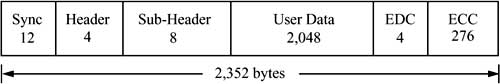
Figure 8-11 Sector layout (2) for CD-ROM/XA according to the Green Book. Data layout of a CD-ROM block in mode 2, form 2.

8.6.1 Form 1 and Form 2
CD-ROM/XA differentiates blocks with form 1 and form 2 formats, similar to the CD-ROM modes:
1. The XA format form 1 in CD-ROM mode 2 provides improved error detection and correction. Like CD-ROM mode 1, four bytes are needed for error detection and 276 bytes for error correction. Unlike CD-ROM mode 1, the eight bytes unused in CD-ROM mode 1 are used for the subheader. Figure 8-10 shows a block (sector), where 2,048 bytes are used for data.
2. The XA format form 2 in CD-ROM mode 2 allows a 13 percent increase in actual data capacity, to 2,324 bytes per block, at the expense of error handling. Form 2 blocks can be used to store compressed data of various media, including audio and video data.
On a CD-DA, CD-ROM, or mixed mode disc, a track always consists of homogeneous data, meaning exclusively audio or computer data. It is thus not possible for the computer to, for example, concurrently read uncompressed audio data and computer data. The main advantage of CD-ROM/XA is that blocks of different media can be stored in one track since they are all coded in CD-ROM mode 2, thus allowing interleaved storage and retrieval.
8.6.2 Compressed Data of Different Media
Using interleaving, CD-ROM/XA allows the storage of different compressed media.
Audio can be compressed at different quality levels with ADPCM (Adaptive Differential Pulse Code Modulation). The total time of a CD-DA can be extended from 74 minutes (without compression) to over 19 hours of lower quality audio by reducing the audio signal to four bits per sample value. This compression is necessary in order to simultaneously retrieve data of other media. The following variants are possible:
• Level B stereo achieves a compression factor of 4:1 compared to a CD-DA audio signal. The level B sampling frequency is 37,800Hz, resulting in a capacity of 4 hours and 48 minutes, based on a CD-DA playback time of 74 minutes. The data rate is about 43Kbyte/s.
• Level B mono achieves a compression factor of 8:1 compared to a CD-DA audio signal. At this quality, 9 hours and 36 minutes of audio can be stored. The data rate is about 22Kbyte/s.
• Level C stereo also achieves a compression factor of 8:1 and thus yields results in the same storage capacity and data rate as level B mono. The level C sampling frequency is 18,900Hz.
• Level C mono works with a compression factor of 16:1, resulting in a maximum of 19 hours and 12 minutes with a data rate of about 11Kbyte/s.
MPEG audio does not use ADPCM coding (see Section 7.7.2 regarding compression) and is thus still not compatible with the CD-ROM/XA specification. For other media, CD-ROM/XA is based on existing standards. Media-specific coding and decoding is not part of the CD technology. Thus, only references to other standards are given here.
When building applications using the CD-ROM/XA format, the maximum data rate must be considered when choosing the medium and the corresponding quality. The same applies to other CD-based formats, such as CD-I.
The logical format of CD-ROM/XA uses the ISO 9660 specification. ISO 9660 provides for interleaved files, that is, multiple files that are interleaved with each other. However, ISO 9660 does not address channel interleaving, that is, alternating sectors with audio, video, and other data within a file. ISO 9660 does not prescribe the content of a file. Unfortunately, the term file interleaving is often used for interleaved files as well as for channel interleaving.
An example of a system using this technology is a file system for PC systems under Unix described as early as 1992 [Kle92]. This file system is a component of the Unix kernel and is located under the Unix file system switch. All accesses that do not change data, even to other file systems, are possible this way. The implementation described uses CD-ROM/XA hardware with integrated chips for audio decompression. In this system, low-resolution video can be decoded in software at 15 frames per second.
8.7 Further CD-ROM-Based Developments
The interaction of the different CD-ROM technologies is depicted in Figure 8-12. It should be stressed that the CD-DA, CD-ROM, and CD-ROM/XA specifications should be viewed like layers of a communications system.
Figure 8-12 CD-ROM technologies. Specification of multiple layers.

Fundamentally, the CD-DA specification applies to all layers. However, the sequential development of these layers does not cover all the basic facts in the Red Book. For example, the mixed mode disc is not defined.
Other CD-based developments building on these fundamental technologies have appeared or are appearing to either handle multiple media or specific media and application areas. For the long term as well, it is expected that all further CD technologies will be based on CD-DA, CD-ROM, and CD-ROM/XA.
8.7.1 Compact Disc Interactive
The Compact Disc Interactive (CD-I) was developed by N.V. Philips and the Sony Corporation [vZ89] prior to the specification of CD-ROM/XA. In 1986, CD-I was announced. In 1988 the Green Book [Phi88] was defined based on the Red Book and the Yellow Book [Bas90, BW90a, B.V89, Sv91]. CD-I was originally designed for consumer electronics as an addition to the TV set, and the appropriate devices were available commercially in 1991. However, this system did not become widespread and disappeared entirely from the market by the end of 1997.
CD-I specifies an entire system. It includes a CD-ROM based format (different from CD-ROM/XA) with interleaving of various media and definition of compression for different media. Moreover CD-I defines system software based on the CD-RTOS operating system and output hardware for multimedia data.
The CD-I hardware is called the decoder. It consists of a main processor from the Motorola 68000 family together with special video and audio chips. It also includes a CD player with a controller and a joystick or mouse interface, and there is provision for a connection to a RGB monitor or a television. CD-I devices, which are the same size as video recorders, were intended to replace and extend CD-DA devices in the consumer environment.
The CD-I system software consists of the CD-RTOS operating system, a derivative of OS/9 with extensions for real-time processing.
8.7.1.1 Audio Coding
CD-I audio coding includes different quality levels with differing capacity and data rate. The different modes (CD-DA audio, A, B, and C) are listed in Table 8-3. The close relationship between CD-I and CD-ROM/XA is easy to see. CD-I was the basis for the CD-ROM/XA definition. The lower data rates can be used in combination with images or motion pictures. Multiple channels of lower quality can also be used for playback in different languages.
Table 8-3 CD-I audio coding

8.7.1.2. Coding of Images
CD-I can be used to code images at different quality levels and resolutions. The following short overview shows that different data sizes and data rates are possible:
• The YUV mode is used for reproduction of natural images with many colors. The image resolution is 360×240 pixels, and the luminance component Y and the chrominance components U and V are coded using a total of 18 bits per pixel, allowing 262,144 colors per image. The resulting image size is:
![]()
• Using a Color Look-Up Table (CLUT), CD-I can work with four bits per pixel. Alternatively, three, seven, or eight bits per pixel are possible. This mode is suitable for simple graphics with fast retrieval using a preloaded color table. With four bits per pixel, at most 16 colors can be simultaneously presented. At a resolution of, for example, 720×240 pixels and four bits per pixel, the resulting image size is:
![]()
• The RGB mode is intended for very high-quality image output. Red, green, and blue components are each coded with five bits. Including an extra bit per pixel, colors are coded using a total of 16 bits per pixel, allowing up to 65,536 colors to per image to be displayed. With a resolution of 360×240 pixels, the data size for an image is:
![]()
8.7.1.3 Coding of Animations
Animations are run-length encoded using approximately 10,000 to 20,000 bytes per image. In the future, CD-I will use MPEG to code video. Although the CD-I file format was strongly influenced by the ISO 9660 standard, it is not completely compatible.
The CD-I technology was originally intended for the consumer marketplace. It is interesting in the context of the CD because it provided the basis for the CD-ROM/XA.
8.7.2 Compact Disc Interactive Ready Format
Although the different CD formats all stem from the CD-DA standard, it is not necessarily possible to play a CD-I disc on a CD-DA device. Furthermore, one cannot assume that all CD-DA devices will, for example, be replaced by CD-I devices. There was thus a need for a specification of an optical disc format that can be played on traditional CD-DA devices as well as on CD-I devices. This format is called the Compact Disc Interactive Ready Format [Fri92a].
In the Compact Disc Interactive Ready Format, the track pregap area between the index points IP0 and IP1 at the beginning of each track is increased from two to three seconds to a minimum of 182 seconds. The CD-I-specific information is stored in this area. This could be, for example, details about individual pieces, images, or biographies of the composer and the conductor.
A CD-I Ready Disc can be played in three different ways:
• With the usual CD-DA playback, the CD-I information in the track pregap is ignored and only the audio will be played.
• The second mode uses only the CD-I data in the track pregap. This can contain data of any media, which can be read, presented, and interpreted, possibly interactively. The CD-DA audio data of the track are not played.
• In the third mode, during the audio playback, the CD-I data from the track pregap are presented concurrently. This method is similar to the mixed mode disc (see Section 8.5). First, the CD-I data are read and stored. Then the audio information is output together with the corresponding data from the track pregap (which were read beforehand). In this way the data can be presented simultaneously.
8.7.3 Compact Disc Bridge Disc
The Compact Disc Bridge Disc (CD Bridge Disc)—like the CD-I Ready Disc—has the goal of enabling a CD to be output on devices supporting different formats. While CD-I Ready Disc specifies a disc format to allow output on either a CD-DA device or on a CD-I device, CD Bridge Disc specifies a disc format to allow output on either a CD-ROM/XA device or on a CD-I device [Fri92a].
Figure 8-13 shows the definitions of the aforementioned CD formats for output on devices using different standards.
Figure 8-13 Compact Discs for output on devices with multiple formats. Mixed mode disc, CD-I Ready Disc, and CD Bridge Disc.

A CD Bridge Disc must satisfy both the CD-I and the CD-ROM/XA specifications, though it does not exploit all their capabilities. A common subset is defined that holds for both formats. All tracks with computer data (as opposed to uncompressed audio data as per CD-DA) must be recorded using CD-ROM mode 2. The disc may not contain any CD-ROM mode 1 blocks. Audio tracks (CD-DA) may follow the computer data tracks.
Another example of compatibility with both specifications is the track entry in the table of contents at the beginning of the CD. References to CD-I tracks are never included in this area. All tracks with data are thus marked as CD-ROM/XA tracks.
8.7.4 Photo Compact Disc
The Photo Compact Disc from Eastman Kodak and N.V. Philips is an example of a CD Bridge Disc [Fri92a] used for storing high-quality photographs. The Photo CD is based on CD-WO, so part of the Photo CD is delivered already written, and a second part can be written once. As a CD Bridge Disc, the Photo CD can be read by either CD-I or CDROM/XA devices. Additionally, it can be read and written by CD-WO devices and by special Photo CD devices.
The Photo CD was announced at Photokina ‘90 as the Kodak Photo CD System and will be licensed by Agfa-Gevaert.
The Photo CD is based on the following process [Kle92]: photographs are created using using conventional cameras and film. After the film is developed, the pictures are digitized using a resolution of eight bits for the luminance component and eight bits for each of two chrominance components. Each pixel is thus coded in 24 bits. Each photo is then coded in up to six resolutions as an ImagePac (see Table 8-4). This coding in multiple resolutions is analogous to the idea of hierarchical coding of images in JPEG (see Section 7.5.5 regarding compression). Each ImagePac usually requires 3–6 Mbytes of storage, depending on image complexity.
Table 8-4 Resolution of frames on a Photo CD.

The integration of photos with digital computer and television technology enables many new professional and consumer applications. For example, images can be displayed using a computer or TV. Using different resolutions, a digital zoom feature can be easily implemented. Multiple images can be displayed in an overview presentation by using a lower resolution. Using software, images can be modified after the fact and/or inserted into documents.
8.7.5 Digital Video Interactive and Commodore Dynamic Total Vision
Digital Video Interactive (DVI) specifies—like CD-I—different components of a system. DVI consists of compression and decompression algorithms; highly integrated, dedicated hardware components for compression and decompression of video in real time; a user interface (the Audiovisual Kernel, AVK); and a fixed data format. In contrast to CD-I, the emphasis is not on the CD technology, but on the compression algorithms [HKL+91, Lut91, Rip89].
DVI uses CD-ROM mode 1 with the block format depicted in Figure 8-8. In addition, for the CD-ROM, DVI uses the ISO 9660 format as the basis for the AVSS (Audio/Video Support System) interleaved file format. Commodore’s CDTV (Commodore Dynamic Total Vision), for example, also uses CD-ROM mode 1 and the ISO 9660 format. It should be noted that ISO 9660 distinguishes among different Interchange Levels. DVI uses the basic mode (Interchange Level 1), where among other restrictions, filenames are limited to 8-point-3 characters from a predefined character set. CDTV uses the Interchange Level 2, which allows, among other things, file names of up to 30 characters. Today neither system has any commercial significance.
8.8 Compact Disc Recordable
All of the CD technologies considered until now (except the Photo CD discussed in Section 8.7.4) do not allow users to write to discs, limiting the technologies’ application domain. Research laboratories thus have developed and are developing, in parallel with read only storage media, compact discs that can be written once or multiple times.
The Compact Disc Recordable (CD-R), specified in the second part of the Orange Book [Phi91], like WORM (Write Once Read Many) allows the user to write a CD once and then read repeatedly [AFN90].
8.8.0.1 Principle of the CD-R
Figure 8-14 shows a sectional view through a CD-R vertically through the disc surface and the data track. The CD-R has a pre-engraved track. In all read-only CDs, the substrate (a polycarbonate) adjoins the reflective layer. In the CD-R, there is an absorption layer between the substrate and the reflective layer. Strong heat has the effect of irreversibly modifying this layer’s reflective properties for laser beams.
Figure 8-14 Sectional view of a CD-R disc, vertically through the data track. Schematic representation.
In the original state, a CD reader sees a track consisting of lands. Using a laser with an intensity of three to four times that of a read-only device’s, the absorption layer in the area of the pre-engraved track is heated to above 250˚C. This alters the material such that the reflected laser light now corresponds to a pit. This gives rise to the most noteworthy property of the CD-R. The data on a CD-R can be read by traditional devices designed exclusively for read-only CDs.
8.8.0.2 Sessions
All of the CD systems described so far assume that a lead-in area precedes the actual data area, and that this is followed by a lead-out area (see Section 8.4.4). The lead-in area holds a table of contents, which is needed by all playback devices in order to ensure correct positioning. However, when writing a CD-R this area cannot be written on the disc until after the write procedure has finished. Thus, all data on a CD-R would have to be copied to the disc in one atomic action. In the meantime, the disc would not be readable by other devices.
To solve this problem, the principle of multiple sessions, depicted in Figure 8-15, was introduced. Each session has its own lead-in and lead-out areas. In each write procedure, all the data for a session with its table of contents is written. The disc can then be read by other devices.
Figure 8-15 Layout of a “hybrid disc.” Division into multiple sessions.
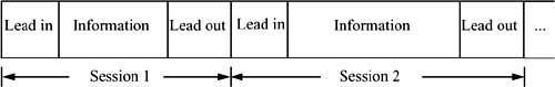
With this addition, the structure of a CD was extended to a maximum of 99 sessions. However, due to the space required for the lead-in and lead-out areas, at most 46 sessions—even with empty data areas—can be stored. In turn, each session consists of a lead-in area, a data area, and a lead-out area. Until 1992, all commercially available devices could read only one session. CD-R discs with only one session are called regular CD-R; those with more than one session are called hybrid CD-R.
CD-R recorders operate at up to eight times the data rate of a player. This shortens the write procedure, but also places requirements that cannot be ignored on the computer and additional software needed to produce a CD-R. This data rate must be sustained throughout the write procedure. Simpler programs thus first create an image of the CD-R on a hard disk. The data are then transferred to the CD-R in a second step. A storage-saving approach produces the data in the correct order and transfers them (without intermediate storage of the whole CD-R) at the necessary rate to the CD-R [Wep92].
Given the same price and features, the CD-R could, for example, be a substitute for CD-DA discs. However, the CD-R production process is and will continue to be more expensive than that of traditional CDs. Thus, it is used in other application areas. CD-Rs can be used whenever, for technical or legal reasons, large quantities of data need to be stored in an irreversible fashion. CD-R also finds application in the area of CD publishing because the expensive and time-consuming process of creating a master can be omitted. It is thus possible to produce limited-circulation editions that are very up to date.
8.9 Compact Disc Magneto-Optical
The Compact Disc Magneto Optical (CD-MO), specified in the first part of the Orange Book [Phi91], has a high storage capacity and allows the CD to be written multiple times.
Figure 8-16 CD-WO and CD-MO in relation to other CD technologies: structure in multiple layers.

The magneto-optical technique is based on the principle that at higher temperatures, a weak magnetic field is needed to polarize the dipoles in certain materials. The block (sector) to be written is heated to above 150˚C. At the same time, a magnetic field about ten times the strength of the Earth’s magnetic field is applied. At this point, the material’s dipoles are polarized towards this magnetic field. A pit is coded with a downwards-facing magnetic north pole. A land is coded using the opposite orientation.
In order to erase a block (sector), the area around the block is subjected to a constant magnetic field while it is heated.
If the CD is illuminated by a laser, the polarization of the light changes depending on the magnetization of the CD. In this way, the information can be read.
8.9.0.3 Areas of a CD-MO
A CD-MO consists of an optional read-only area and the actual rewritable area.
The read only area (premastered area in Figure 8-16) contains data written on the disc in a format specified for this purpose. In Figure 8-16, this relationship is indicated using the arrows between the premastered area of a CD-MO and the read only technologies. Thus, the read only area can be read using existing playback devices.
The rewritable area of a CD-MO cannot be read using existing CD-DA, CD-ROM, CD-ROM/XA, or CD-WO devices due to the fundamentally different technology used for reading and writing. Figure 8-16 shows the relationships between this recordable area and the underlying magneto-optical technology. This technology is thus incompatible with all the other CD technologies, although it was specified using the same system parameters as the other techniques. For example, the dimensions and the rotational speed are the same.
8.10 Compact Disc Read/Write
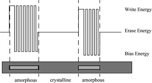
The Compact Disc Read/Write (CD-RW) is a further development of the CD-WO that, due to its physical makeup, can be repeatedly rewritten. This is achieved by using the reversible changeability of crystalline structures. The layers of a CD-RW are depicted in Figure 8-17.
Figure 8-17 Layers of a CD-R/W. The upper/lower layers are protective layers that increase the stability of the CD-R/W.

Like the CD-R, phase changes are made by heating the crystal layer using the laser. However, in this case the energy is emitted as a pulse waveform (see Figure 8-18).
Figure 8-18 In the “pit” phases, the recording beam varies between the write energy and the bias energy in order to prevent overheating in the crystal.
However, using this technology it is no longer possible to read CD-RW discs on every CD player on the market since the reflectivity is lower than that of a CD or CD-R (see Table 8-5). In order to compensate for these effects, newer CD systems automatically amplify the signal as necessary. The other technology and logical structure are the same as the systems described earlier.
Table 8-5 Comparison of reflectivity of different CD variants.

8.11 Digital Versatile Disc
The Digital Versatile Disc (DVD) is, particularly in view of its larger storage space, the logical refinement of the CD-ROM/CD-R/CD-RW technologies. In 1994, large electronics companies began work on a CD with higher storage capacity. In early 1995, several companies joined to form the DVD Consortium and passed the first standards in the framework of the DVD Forum in April 1996.
8.11.1 DVD Standards
The DVD Consortium set down the specifications for DVD in the publications “Book A-E.” Each Book defines a standard:
• DVD Read Only Specification (DVD-ROM, Book A): High capacity storage medium, successor to the CD-ROM,
• DVD Video Specification (DVD-Video, Book B): Specific application of DVD to distributing “linear” video data streams,
• DVD Audio Specification (DVD-Audio, Book C): Specific application of DVD to distribute pure audio data, similar to the CD-DA,
• DVD Recordable Specification (DVD-R, Book D): Variation of DVD that allows data to be recorded once for later use, and
• DVD Rewritable Specification (DVD-RW, Book E): Type of DVD that, like CD-RW, can be repeatedly written and erased; also known as DVD-RAM (Random Access Memory).
The storage capacity that can be achieved with DVD technology depends on the version (see Table 8-6).
Table 8-6 DVD media variants and their storage capacities. SS: single sided; DS: double sided; SL: single layer; DL: double layer; * indicates term used here.

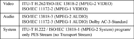
Here it is assumed that the standards listed in Table 8-7 are used for recording audio/video and data.
Table 8-7 DVD standards.
It should be noted that the capacity of a double-layer DVD is less than that of a double-sided DVD because the crosstalk that occurs when reading through the outer layer must be reduced.
8.11.1.1 Technical Basics
DVDs achieve a higher capacity than CD-ROMs by using smaller pits (which yields a higher track density), combined with a larger data area, more efficient coding of bits, more efficient error correction and lower sector overhead (see Figure 8-19).
Figure 8-19 Data on a DVD. The track pitch and the pit width are less than a CD’s.

From the standpoint of information technology, a DVD consists of a number of blocks of 37,856 bytes each. Each block contains 16 sectors plus additional data for error detection and correction. Individual sectors consist of 2,064 bytes divided into 12 rows as shown in Table 8-8. The first 12 bytes in the first row contain the sector header (sector ID, sector ID error correction, and six reserved bytes). The rest of the block, except the last four bytes, which contain the error detection code, holds user data.
Table 8-8 Structure of a DVD sector.

In order to transfer parallel streams better, DVD interleaves 16 sectors together. This also provides better robustness against errors. The result of the interleaving is a block of 192 rows (16 sectors × 12 rows per sector = 192 rows). At the end of each row ten bytes are added for further error correction, resulting in an additional 16 rows at the end of each block. Thus, only 33,024 bytes of each 37,856-byte block are available for user data, yielding a payload of only 87 percent.
8.11.2 DVD-Video: Decoder
In the following, some principles of DVD technology are illustrated by examining a decoder in the context of the DVD video specification. The decoder provides for the following six layers to transfer MPEG data:
• Layer 1: Synchronization, 8/16-demodulation, sector detection
Altogether eight synchronization elements are inserted into the 8/16-coded bit streams. This layer recognizes and detects sector boundaries. At this step, the starting channel bit rate is 26.16 Mbit/s, while the ending user data rate amounts to 13 Mbit/s.
• Layer 2: Error detection (EDC) and correction (ECC)
If the EDC check bits differ from the “fingerprint” generated from the data, then the inserted IEC data are used to help correct the error. After this layer, the user data rate is reduced to about 11.08 Mbit/s (about 2 Mbit/s are used for error correction, parity, and IEC data).
• Layer 3: Descrambling and decryption
The data on the DVD are permuted in order to impede (or render impossible) unauthorized reading. Additional encryption is used for copy protection.
• Layer 4: EDC verification
This is another error detection step.
• Layer 5: Track buffer
The track buffer makes it possible to deliver the data that are read from the DVD at a fixed rate (11.08 Mbit/s) to an application at a variable data rate. Specific packets included in the data stream to control the player are dropped, yielding a maximum data stream of 10.08 Mbit/s.
• Layer 6: Transfer of data to MPEG System Decoder
In this step, the data stream is demultiplexed into substreams that are delivered to their respective applications.
8.11.3 Eight-to-Fourteen+ Modulation (EFM+)
The lowest layer of the communication channel performs Eight-to-Fourteen+ Modulation (EFM+), U.S. Patent #5,206,646, which is mainly intended to reduce the DC component of the data stream. Like Eight-to-Fourteen Modulation, EFM+ eliminates certain sequences of bits (many zeroes). The main advantages of the 8/16 modulation are that no filler bits are necessary and that simpler decoding mechanisms are possible.
8.11.4 Logical File Format
The DVD file format (ISO 13490) is based on the ISO 9660 format. The ISO 13490 file format incorporates multisession capabilities specifically adapted to the features of the DVD technology.
8.11.5 DVD-CD Comparison
Table 8-9 provides an overview of the most important parameters of DVD technology compared with conventional CD technology.
Table 8-9 Comparison of DVD with conventional CD technology.

8.12 Closing Observations
In the area of optical storage media, as far as can be seen today, Compact Disc technology or its further development in the form of the DVD, will predominate for all types of storage. The interrelationships among the different, mostly de facto, standards (see Figure 8-20) allow a wide field of application. With the exception of the CD-MO, the technologies are all based on the CD-DA and its optical technology.
Figure 8-20 Important CD technologies and their relationships to one another.

A closer examination and comparison of the formats reveals the chronological sequence in which the CD technologies were specified. For example, CD-ROM in mode 1 defines improved error handling for computer data. CD-ROM/XA form 1, which is based on CD-ROM mode 2, provides the same service. It would thus be possible to eliminate CD-ROM mode 1 if there weren’t already many applications that use it. The compression methods of CD-ROM/XA should permit use of the JPEG, MPEG, H.261, and CCITT ADPCM standards and not, for example, be limited to coding techniques supported by inexpensive chips already integrated on CD-ROM/XA controller boards.
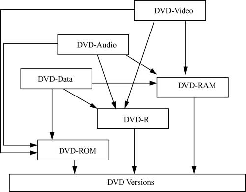
Figure 8-21 Important DVD technologies and their relationships to one another.
A major disadvantage of this technology is the relatively high average access time of at best about 200ms. Even in the future, this will probably not be improved upon considerably. The data rate can be further increased by simultaneously reading multiple parts of the track that run parallel to one another. However, by then cache techniques may buffer the entire CD, so that the access time will no longer be determined by the CD device. The incompatibility between the CD and the CD-MO is unavoidable, but will become less important in the future due to CD-R/W and DVD-RAM technology.
The storage capacity achievable using CDs or DVDs is sufficient for many current systems. The storage density of up to 15.9 Gbytes obtainable today using DVDs is already sufficient for complex multimedia applications. With the quick progress in storage density, it is possible to imagine there will be further improvements in this area. As soon as stable robust semiconductor lasers with higher frequencies are available, a further jump in the storage density of optical media could follow.
The data rate of 10 Mbit/s obtainable with DVDs generally suffices to achieve very high quality audio and video playback with all currently used video and audio codings, such as MPEG-2 for video. However, this is not true for studio or movie theater quality. In this area, completely new developments are expected.