
Chapter 17
Cisco Switches and Routers
Objectives
Upon completion of this chapter, you will be able to answer the following questions:
What are Cisco LAN switches?
What is the Cisco LAN switch boot process?
What are Cisco small business routers?
What is the Cisco router boot process?
Key Terms
There are no key terms for this chapter.
Introduction (17.0.1)
By now, you must be more than ready to test your knowledge and skills on a larger network. Larger networks require switches and routers. Switches and routers turn your LAN into part of a WAN, and your WAN into part of the World Wide Web, so you will want to know how to make them work. This chapter is the perfect starting point for you.
Cisco Switches (17.1)
Ethernet switches are Layer 2 devices that forward Ethernet frames. Switches can be interconnected to allow more devices to be connected.
Connect More Devices (17.1.1)
Home and small business networks usually do not require more than one or two networking devices to be able to function efficiently. A wireless router, equipped with wireless connections and a few wired connections, is the only piece of networking equipment that is necessary to provide sufficient connectivity for the average small group of users. These routers are configured through a web browser and have an easy-to-use graphical user interface (GUI) that guides you through the most common configuration items.
Wireless routers that are designed primarily for home use are not appropriate for most business networks that must support more than a few users. Modern networks use a variety of devices for connectivity. Each device has certain capabilities for controlling the flow of data across a network. A general rule is that the higher the device is in the OSI model, the more intelligent it is. This means that a higher-level device can better analyze the data traffic and forward it based on information not available at lower layers. As an example, a Layer 2 switch can filter the data and send it only out of the port that is connected to the destination, based on the MAC address.
As switches and routers evolve, the distinction between them may seem blurred. One simple distinction remains: LAN switches provide connectivity within the local-area networks of the organization, whereas routers interconnect local networks and are needed in a WAN environment. In other words, a switch is used to connect devices on the same network. A router is used to connect multiple networks to each other.
Figure 17-1 shows a series of Cisco switches.
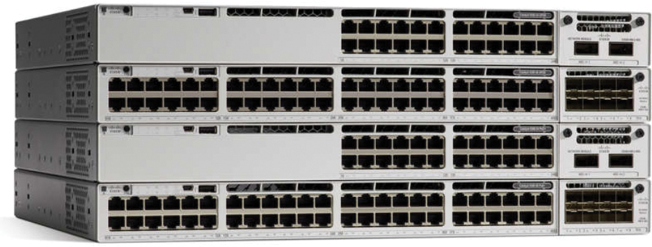
Figure 17-1 Cisco Catalyst 9300 Series Switches
Figure 17-2 shows a series of Cisco routers.

Figure 17-2 Cisco 4300 Series Routers
In addition to switches and routers, other connectivity options are available for LANs. Wireless access points that are deployed in enterprises enable computers and other devices, such as smartphones, to wirelessly connect to the network, or share broadband connectivity. Firewalls guard against network threats and provide security, network control, and containment.
Cisco LAN Switches (17.1.2)
When a LAN grows to the point where the four Ethernet ports provided by the wireless router are not enough for all of the devices that need to attach to the wired network, it is time to add a LAN switch to the network. A switch can provide connectivity at the access layer of a network, connecting devices to a LAN. A switch can allow the network to grow without replacing central devices. When you‛re choosing a switch, there are a number of factors to consider, including the following:
Type of port
Speed required
Expandability
Manageability
Type of Port
When selecting a switch for your LAN, choosing the appropriate number and type of port is critical. Most lower-cost switches support only copper twisted-pair interface ports. Higher-priced switches may have fiber-optic connections. They are used to link the switch to other switches that may be located over long distances. The Cisco Catalyst 9300 series has a variety of options depending on your environment (see Figure 17-3).

Figure 17-3 The Cisco Catalyst 9300 Series
Speed Required
Ethernet twisted-pair interfaces on a switch have defined speeds. A 10/100 Ethernet port can function only at 10 megabits per second (Mbps) or at 100 Mbps. This means that even if the device that you are connecting to the 10/100 switch interface port is capable of connecting at gigabit speeds, the maximum speed at which it is able to communicate is 100 Mbps. Switches may also include gigabit Ethernet ports. If your Internet connection is more than 100 Mbps, a gigabit port is necessary to take advantage of the higher Internet bandwidth. Gigabit Ethernet ports also operate at 10/100 Mbps. Gigabit Ethernet is sometimes represented as 1000 Mbps. The Cisco Catalyst 9300 48S switch in Figure 17-4 has two 40 Gbps uplink ports to provide a fast path for the 48 ports to access the rest of the network and the Internet.

Figure 17-4 The Cisco Catalyst 9300 48S Switch
Similar to a switch port, Ethernet NICs operate at specific bandwidths such as 10/100 or 10/100/1000 Mbps. The actual bandwidth of the attached device is the highest common bandwidth between the NIC on the device and the switch port.
Expandability
Networking devices come in both fixed and modular physical configurations. Fixed configurations have a specific type and number of ports or interfaces. Modular devices have expansion slots that provide the flexibility to add new modules as required. Figure 17-5 shows a Cisco Catalyst 9600 chassis in which you can install different configurations of hardware to address your particular environment.

Figure 17-5 Cisco Catalyst 9600 Chassis
Manageability
Many basic inexpensive switches are not configurable. A managed switch that uses a Cisco operating system enables control over individual ports or over the switch as a whole. Controls include the ability to change the settings for a device, add port security, and monitor performance. The network administrator in Figure 17-6 is directly connecting to a Cisco Catalyst switch using a console cable.

Figure 17-6 Network Administrator Managing Network Switches

Video—Components of a LAN Switch: Part 1 (17.1.3)
Refer to the online course to view this video.
Video—Components of a LAN Switch: Part 2 (17.1.4)
Refer to the online course to view this video.
LAN Switch Components (17.1.5)
The Cisco Catalyst 9300 switch shown in Figure 17-7 is suitable for small- and medium-sized networks. It provides 24 1-Gbps data ports with Power over Ethernet (PoE) so that some device types can be directly powered from the switch. It also has two modular 40 Gbps uplink ports. The LEDs indicate the port and system status of the switch. The switch is equipped with a console and storage ports for device management.

Figure 17-7 Cisco Catalyst 9300 24 UPOE Switch
Switch Boot Process (17.2)
Cisco switches go through a boot process similar to that of your computer or smartphone. Ethernet switches in small networks usually do not require any configuration. They are designed to work out of the box.
Power Up the Switch (17.2.1)
Cisco switches, like most switches, are preconfigured to operate in a LAN as soon as they are powered on. All of the interface ports on the switch are active and will begin forwarding traffic immediately after devices are plugged into them. It is important to remember that no security settings are enabled by default. You need to configure the basic security settings before connecting the switch to the network.
The three basic steps for powering up a switch are as follows:
Step 1. Check the components.
Step 2. Connect the cables to the switch.
Step 3. Power up the switch.
When the switch is powered on, the power-on self-test (POST) begins. During POST, the LEDs blink while a series of tests determines whether the switch is functioning properly.
Note
You can also attach cables after power is applied.
POST is completed when the SYST LED rapidly blinks green. If the switch fails POST, the SYST LED turns amber. If a switch fails POST, you need to return the switch for repairs.
When all startup procedures are finished, the Cisco switch is ready to configure.
Step 1. Check the components. Ensure all the components that came with the switch are available (see Figure 17-8). These components could include a console cable, power cord, Ethernet cable, and switch documentation.

Figure 17-8 Components for Connecting to a Switch
Step 2. Connect the cables to the switch. Connect the PC to the switch with a console cable and start a terminal emulation session, as shown in Figure 17-9. Connect the AC power cord to the switch and to a grounded AC outlet.

Figure 17-9 Switch to Laptop Console Connection
Step 3. Power up the switch. Some Cisco switch models do not have an on/off switch, like the Cisco Catalyst 9300 48S switch shown in Figure 17-10. To power on the switch, plug one end of the AC power cord into the switch‛s AC power connector, and plug the other end into an AC power outlet.

Figure 17-10 Back Panel of the Cisco Catalyst 9300 48S
Note
The Cisco Catalyst 9300 switch in Figure 17-10 has redundant power supplies in case one fails.
Video—In-Band and Out-of-Band Device Management (17.2.2)
Refer to the online course to view this video.
In-Band and Out-of-Band Management (17.2.3)
The two methods to connect a PC to a network device to perform configuration and monitoring tasks are in-band and out-of-band management.
In-Band Management
In-band management is used to monitor and make configuration changes to a network device over a network connection. For a computer to connect to the device and perform in-band management tasks, at least one network interface on the device must be connected to the network and have an IP address configured on it. Telnet, SSH, HTTP, or HTTPS can be used to access a Cisco device for in-band management, monitor the network device, or make configuration changes. Telnet and HTTP send all data, including passwords, in cleartext and therefore should be used only in a lab environment.
Out-of-Band Management
Out-of-band management requires a computer to be directly connected to the console port of the network device that is being configured. This type of connection does not require the local network connections on the device to be active. Technicians use out-of-band management to initially configure a network device, because until properly configured, the device cannot participate in the network. Out-of-band management is also useful when network connectivity is not functioning correctly, and the device cannot be reached over the network. Performing out-of-band management tasks requires a terminal emulation client installed on the PC.
IOS Startup Files (17.2.4)
As shown in Figure 17-11, a Cisco device loads the following two files into RAM when it is booted:

Figure 17-11 Memory Location of IOS and Startup Configuration
IOS image file—The IOS facilitates the basic operation of the device‛s hardware components. The IOS image file is stored in flash memory.
Startup configuration file—The startup configuration file contains commands that are used to initially configure a router and switch and create the running configuration file stored in RAM. The startup configuration file is stored in NVRAM. All configuration changes are stored in the running configuration file and are implemented immediately by the IOS.
The running configuration file is modified when the network administrator performs device configuration. When changes are made to the running-config file, it should be saved to NVRAM as the startup configuration file in case the router is restarted or loses power.
Video—Establish a Console Connection (17.2.5)
Refer to the online course to view this video.
Cisco Routers (17.3)
A router is a computer with specialized hardware and a network operating system. A computer, such as a PC running Linux, could even be configured as a router for a small network. Cisco routers have specialized hardware and software designed to provide the features and performance needed for enterprise and service provider networks.
Video—Cisco Router Components (17.3.1)
Refer to the online course to view this video.
Router Components (17.3.2)
Regardless of their function, size, or complexity, all router models are essentially computers. Just like computers, tablets, and smart devices, routers also require the following:
Operating system (OS)
Central processing unit (CPU)
Random-access memory (RAM)
Read-only memory (ROM)
Nonvolatile random-access memory (NVRAM)
Like all computers, tablets, and smart devices, Cisco routers require a CPU to execute OS instructions, such as system initialization, routing functions, and switching functions.
The Cisco Internetwork Operating System (IOS) is the system software used for most Cisco devices, regardless of the size and type of the device. It is used for routers, LAN switches, small wireless access points, large routers with dozens of interfaces, and many other devices.
Router Interface Ports (17.3.3)
Although several different types and models of routers are available, every Cisco router has the same general hardware components.
Figure 17-12 shows a Cisco 4321 Integrated Services Router (ISR).

Figure 17-12 Connections on the Cisco 4321 ISR
The router includes the following connections:
Console ports—Two console ports for the initial configuration and command-line interface (CLI) management access using a regular RJ-45 port and a USB mini-B connector.
Two LAN interfaces—Two Gigabit Ethernet interfaces for LAN access labeled GE 0/0/0 and GE 0/0/1. The GE 0/0/0 port can be accessed through an RJ-45 connection or by using a small form-factor pluggable (SFP) attachment to provide a fiber-optic connection.
Network interface modules (NIMs)—Two NIM expansion slots that provide modularity and flexibility by enabling the router to support different types of interface modules, including serial, digital subscriber line (DSL), switch ports, and wireless.
The Cisco 4321 ISR also has a USB port, a management interface, and an auxiliary port. The USB port can be used for file transfers. The management port can be used for remote management access when the two Gigabit Ethernet interfaces are unavailable. The auxiliary port provides legacy support for a method of connecting a dial-up modem to the router for remote access. The auxiliary port is rarely used in networks today.
Router Boot Process (17.4)
Because the router is just a specialized computer, the boot process is the same as most computers.
Power Up the Router (17.4.1)
Before you begin any equipment installation, it is important to read the Quick Start guide and other documentation that is included with the device. The documentation contains important safety and procedural information.
Step 1. Securely mount the device to the rack (see Figure 17-13).

Figure 17-13 Mounting the Chassis in a Rack
Note
Figure 17-13 shows a typical scenario of mounting the chassis in a rack.
Step 2. Ground the device (see Figure 17-14).

Figure 17-14 Attaching the Ground Wire to the Chassis
Step 3. Connect the power cable (see Figure 17-15).

Figure 17-15 Power Input Connector
Step 4. Connect a console cable. Configure the terminal emulation software on the laptop and connect the laptop to the console port, as shown in Figure 17-16.

Figure 17-16 Attaching a Console Cable to the Device
Step 5. Turn on the router (see Figure 17-17).

Figure 17-17 The Power Switch
Step 6. Observe the startup messages on the laptop as the router boots up (see Example 17-1).
Example 17-1 Cisco 4200 ISR Bootup Messages
Located isr4200-universalk9_ias.16.09.04.SPA.bin
#################################################....
(output omitted)

Package header rev 3 structure detected
IsoSize = 486723584
Calculating SHA-1 hash...Validate package: SHA-1 hash:
    calculated 4155409B:CC0DB23E:6D72A6AE:EA887F82:AC94DC6A
    expected  4155409B:CC0DB23E:6D72A6AE:EA887F82:AC94DC6A
RSA Signed RELEASE Image Signature Verification Successful.
Image validated

        Restricted Rights Legend

Use, duplication, or disclosure by the Government is
subject to restrictions as set forth in subparagraph
(c) of the Commercial Computer Software - Restricted
Rights clause at FAR sec. 52.227-19 and subparagraph
(c) (1) (ii) of the Rights in Technical Data and Computer
Software clause at DFARS sec. 252.227-7013.

      Cisco Systems, Inc.
      170 West Tasman Drive
      San Jose, California 95134-1706

Cisco IOS Software [Fuji], ISR Software (X86_64_LINUX_IOSD-UNIVERSALK9_IAS-M),
  Version 16.9.4, RELEASE SOFTWARE (fc2)
Technical Support: http://www.cisco.com/techsupport
Copyright (c) 1986-2019 by Cisco Systems, Inc.
Compiled Thu 22-Aug-19 18:09 by mcpre

(output omitted)
Management Ports (17.4.2)
Similar to a Cisco switch, the command-line interface on a Cisco router has several ways to access it. The most common methods are as follows:
Console—This method uses a low-speed serial or USB connection to provide direct connect, out-of-band management access to a Cisco device.
SSH—This method is used to remotely access a CLI session across an active network interface, including the management interface.
AUX port—This method is used for remote management of the router using a dial-up telephone line and modem.
The console port is a physical port located on the router. When you‛re using SSH, there must be an active network interface that is configured with a valid IP address for the network. It can be one of the active network interfaces used for network traffic, or it can be the management interface. Figure 17-18 shows ports available for management access.

Figure 17-18 Management Configuration Access
In addition to these management ports, routers also have network interfaces to receive and forward IP packets. Most routers have multiple interfaces that are used to connect to multiple networks. Typically, the interfaces connect to various types of networks, as shown in Figure 17-19, which means that different types of media and connectors are required.

Figure 17-19 LAN and WAN Interfaces
Video—The Cisco Router Boot Process (17.4.3)
Refer to the online course to view this video.
Summary (17.5)

Packet Tracer—Compare In-Band and Out-of-Band Management Access (17.5.1)
In this activity, you will access Cisco devices using in-band and out-of-band management.
The following is a summary of each topic in the chapter:
Cisco Switches—A switch is used to connect devices on the same network. A router is used to connect multiple networks to each other. When selecting a switch for your LAN, choosing the appropriate number and type of port is critical. Lower-cost switches may support only copper twisted-pair interface ports. Higher-priced switches may have fiber-optic connections. They are used to link the switch to other switches that may be located over long distances.
Similar to a switch port, Ethernet NICs operate at specific bandwidths such as 10/100 or 10/100/1000 Mbps. The bandwidth of the attached device is the highest common bandwidth between the device NIC and the switch port. Networking devices come in both fixed and modular physical configurations. A managed switch that uses a Cisco operating system enables control over individual ports or over the switch as a whole. Cisco Catalyst 2960 Series Ethernet switches are suitable for small- and medium-sized networks.
Switch Boot Process—Cisco switches are preconfigured to operate in a LAN as soon as they are powered on. You need to configure the basic security settings before connecting the switch to the network. The three basic steps for powering up a switch are as follows: (1) Check the components, (2) connect the cables to the switch, and (3) power up the switch. When the switch is powered on, the power-on self-test (POST) begins.
There are two methods to connect a PC to a network device to perform configuration and monitoring tasks: out-of-band management and in-band management. Out-of-band management requires a computer to be directly connected to the console port of the network device that is being configured. In-band management is used to monitor and make configuration changes to a network device over a network connection.
A Cisco device loads the IOS image file and the startup configuration file into RAM when it is booted. The IOS image file is stored in flash memory, and the startup configuration file is stored in NVRAM.
Cisco Routers—Routers require an OS, a CPU, RAM, ROM, and NVRAM. Every Cisco router has the same general hardware components: console ports, LAN interfaces, expansion slots for different types of interface modules (for example, EHWIC, Serial, DSL, switch ports, wireless), and storage slots for expanded capabilities (for example, compact flash memory, USB ports).
Router Boot Process—Follow these steps to power up a Cisco router:
Step 1. Securely mount the device to the rack.
Step 2. Ground the device.
Step 3. Connect the power cable.
Step 4. Connect a console cable.
Step 5. Turn on the router.
Step 6. Observe the startup messages on the PC within the terminal window as the router boots.
The most common methods to access the command-line interface on a Cisco router are console, SSH, and Aux ports. Routers also have network interfaces to receive and forward IP packets.
Practice
The following activities provide practice with the topics introduced in this chapter.
Packet Tracer Activities
Packet Tracer—Compare In-Band and Out-of-Band Management Access (17.5.1)
Check Your Understanding Questions
Complete all the review questions listed here to test your understanding of the topics and concepts in this chapter. Appendix A, “Answers to the ‘Check Your Understanding‛ Questions,” lists the answers.
1. A technician is setting up a network in a new room. What is the best device to connect the PCs to each other and to the rest of the LAN?
Router
Switch
Gateway
Firewall
2. During normal operation, from which location do most Cisco switches run the IOS?
Disk drive
Flash
NVRAM
RAM
3. When a router is powered on, where does the router first search for a valid IOS image to load by default?
RAM
Flash memory
NVRAM
ROM
4. Which protocols can be used to access a Cisco switch for in-band management? (Choose two.)
DHCP
FTP
Telnet
SSH
SMTP
5. During troubleshooting procedures, from which location do most Cisco routers load a limited IOS?
NVRAM
Flash
ROM
RAM
6. Which networking devices are used in enterprise networks for providing network connectivity to end devices? (Choose two.)
Firewall
LAN switch
Web server
Router
Wireless access point
7. What is required for a network administrator to perform out-of-band management tasks on a Cisco device?
An active network connection available to the device
A computer directly connected to the console port of the device
A valid IP address configured on VLAN 1
SSH enabled and functional on the device
8. What is the first action in the boot sequence when a switch is powered on?
Load boot loader software
Perform low-level CPU initialization
Load the default Cisco IOS software
Load a power-on self-test program
9. What are functions of NVRAM? (Choose two.)
To store the startup configuration file
To store the ARP table
To store the routing table
To retain content when power is removed
To contain the running configuration file
10. Which ports can be used for the initial configuration of a Cisco router? (Choose two.)
Flash slot
AUX
WAN interface
Console
LAN interface
11. Which files are loaded into the RAM of a Cisco switch when it is booted? (Choose two.)
File that contains customer settings
Startup configuration file
IOS image file
Routing table
The contents of the saved configuration file in NVRAM
12. Which information does the show startup-config command display?
The bootstrap program in ROM
The contents of the current running configuration file in RAM
The IOS image copied into RAM
The contents of the saved configuration file in NVRAM