
Inductive devices
Relays
Electromagnetic relays make use of the magnetic field in the core of an inductor to alter the setting of a mechanical switch. There is an overlap in the meanings of the words relay and contactor; in general a relay is a comparatively low-voltage low-current device, and a contactor is designed to deal with much higher levels of voltage, current or both.
• Contactors are not generally considered to be electronic components and therefore do not feature in this book. For details of contactor construction and use you should consult a specialized text of electrical engineering.
The essential parts of either device are a coil with a soft magnetic core, a moving armature, and a set of contacts which are actuated by the movement of the armature, and which are insulated from the coil and from the metal frame of the relay. The coil circuit is known as the primary circuit of the relay, and the contact circuit as the secondary. The principles of the traditional form of relay are illustrated in Figure 6.1. Relays can, with some redesign of the magnetic circuit, be used on AC, making use of the principle that an armature will move so as to close a magnetic circuit when the energizing coil is driven by AC.
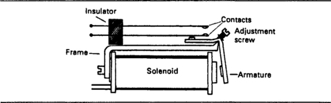
Figure 6.1 Working principles of the traditional type of relay. When the solenoid is magnetized it attracts the armature, and the lever action then closes the contacts.
• You might argue that since a relay can carry out a power-amplifying action it is not strictly speaking a passive component. From the point of view of this book I take passive components to mean electronically passive, not using thermionic amplification or the action of semiconductors.
• Many of the applications for the traditional type of relay have been filled more recently by the use of reed relays (see later, this chapter) and by the use of semiconductor devices such as thyristors, which are active devices and therefore outside the scope of this book. Devices using optical coupling and triac switching are generally listed under the heading of relays in catalogues.
In the mechanical type of relay, the power that is dissipated in the operating coil will determine the mechanical force that is available. This is sometimes specified as pull-in power, the minimum power that is needed to make the contacts operate. The holding power is also sometimes specified, the power that is needed to keep the contacts switched over after they have been pulled in. There is usually a significant difference between the two values, so that if a relay is intended to remain activated for a long period after initial activation, then the dissipated power can be considerably reduced by lowering the applied voltage or current so that only the hold-in power is dissipated. A maximum power dissipation figure will also be specified which must not be exceeded if overheating is to be avoided, and in high ambient temperatures this maximum value will have to be derated. The range of power levels is sometimes quoted in terms of operating voltage for a particular coil, so that a relay nominally intended for 12V operation might be assigned a voltage range of 9–13 V. Where relays are intended for AC operation, nominal volt-amp ratings are shown as well as the usual voltage and current ratings for the coil.
• Many uses for mechanical relays depend heavily on the isolation that can be achieved between the primary and the secondary circuits. Some wiring regulations prohibit the use of solid-state relay equivalents on the grounds that such isolation is more difficult and that fail-safe operation (the secondary circuit remains open when a fault occurs) is less certain. These objections can now be overcome, but while the prohibitions remain in force they must be respected.
The figures for test voltage and insulation resistance are therefore important. The test voltage relates to a flash-test, a high voltage applied for a specified time, usually one minute, in which time no signs of breakdown should be visible when the relay is operated at normal temperature, pressure and humidity. A typical test voltage is 2 kV. The insulation resistance is measured at a high voltage, less than that used for the flash test, and typically 500 V. Insulation resistance of 100 MΩ minimum is normal, and some applications call for 1012 Ω insulation performance. This level of insulation resistance can be achieved, but not if the construction makes use of nylon (whose insulation resistance decreases dramatically in damp and warm conditions).
For a mechanical component, the life, as measured by the expected number of operations before failure, is important. Often only the mechanical life is quoted, typically 107 operations. When both electrical life and mechanical life are quoted, the electrical life is usually less by a factor of 10–100. This reflects the main limitation on the life of a relay, which is damage to, or degradation of, the contacts rather than total failure of mechanical operation. The operating temperature range is restricted compared to other electronic components, usually –20°C to +60°C. A few relay types specify maximum mechanical shock in terms of acceleration in ‘g’ units (g = 9.81 ms−2) while the relay is operating, and this part of the specification may be of importance in industrial applications.
The coil resistance of a relay is usually available as part of the printed specification, but figures for coil inductance are harder to come by. The importance of coil inductance arises when the DC current through the coil is controlled by any form of switch, whether mechanical or electronic, because when the coil current is switched off there will be a reverse-EMF whose value will be given by:
Where L is inductance and di/dt is the rate of change of current through the coil, which will be rapid when the coil is being switched off. The inductance of most relay windings is substantial, and a relay coil should never be driven from a semiconductor collector circuit unless there is diode protection, using the circuit shown in Figure 6.2. Emitter connection may be permissible, subject to the ratings of the semiconductor device. Where the relay coil is controlled by a mechanical switch, diode suppression of back-EMF is not strictly necessary, and a series resistor–capacitor suppression circuit can be used. Manufacturers of relays will advise on the suppression circuits that are most appropriate for any particular relay.
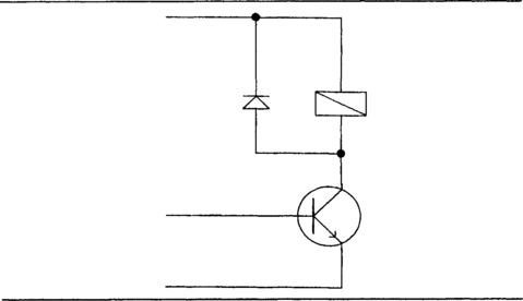
Figure 6.2 Protecting semiconductor components when the coil of a relay is driven by the collector terminal of a transistor or other semiconductor.
Relay contacts deserve particular attention. Contact configurations are specified in terms of the number of poles and whether these are normally closed (NC), normally open (NO) or change-over (CO). For some applications of relays, the contacts spend most of their time closed with current passing; in other applications the contacts are open for most of their lives, exposed to what may be a corrosive atmosphere. For some applications, contacts must have as low a resistance as possible when closed; for other applications the resistance is much less important than lack of corrosion and damage when the contacts make and break at frequent intervals. An ideal contact material would have very low resistance, would need very little force exerted between the contacts to keep the resistance low, would be robust, resistant to corrosion, durable and cheap. There is no single ideal material, and so the contact materials that are used must be selected for the particular application.
In general, contact ratings for DC will be much lower than for AC. This is because the most destructive effect on contacts is arcing, a spark which is drawn out into a spluttering discharge or flare as the contacts open, and which will cause metal to be transferred from one contact to another or oxidized. Arcing under AC is of short duration, because the alternating current drops to zero twice per cycle and because the reversal of voltage means that material will not always be moved in the same direction. The effect of arcing is so serious that most relays are rated to use no more than 24 V DC at their maximum current as compared to 240 V AC at the same current. These AC ratings, however, assume that the load will be resistive, and considerable derating will be needed for a reactive load.
The amount of the contact resistance depends on the area of contact, the contact material, the amount of force that presses the contacts together, and also in the way that this force has been applied. For example, if the contacts are scraped against each other (a wiping action) as they are forced together, then the contact resistance can often be much lower than can be achieved when the same force is used simply to push the contacts straight together.
In general, large contact areas are used only for high-current operation and the contact areas for low-current relays as used for electronic circuits will be small. The actual area of electrical connection will not be the same as the physical area of the contacts, because it is generally not possible to construct contacts that are precisely flat or with surfaces that are perfectly parallel when the contacts come together. This problem will be familiar to anyone who has renewed the ignition points in a car in the days before electronic ignition circuits. Since the size of the relay determines the amount of contact pressure that can be used, and the area of contact is rather indeterminate, then the main factor that affects contact resistance is the material of the contacts themselves.
The relay designer has the choice of making the whole of a contact from one material, or of using electroplating to deposit a more suitable contact material. By using electroplating, the bulk of the contact can be made from any material that is mechanically suitable, and the plated coating will provide the material whose resistivity and chemical action is more appropriate. In addition, plating makes it possible to use materials such as gold and platinum which would make the contacts impossibly expensive if used as the bulk material. It is normal, then, to find that contacts for switches are constructed from steel or from nickel alloys, with a coating of material that will supply the necessary electrical and chemical properties for the contact area.
The choice is never easy, because the materials whose contact resistance is lowest are in general those which are most readily attacked chemically by the atmosphere. In addition, some materials which can provide an acceptably low contact resistance exhibit ‘sticking’, so that the contacts do not part readily and may weld shut. The other main problems are burning and oxidation. The spark current which passes at the time when contacts are opening can cause melting of the contacts or cause the metal to combine chemically with the oxygen in the atmosphere (oxidation or ‘burning’). Of these two, oxidation is a more severe problem than melting, because the oxides of most metals are non-conductors, so that oxidation causes a large rise in insulation resistance, even to the point of making the contacts useless. This is the usual form of electrical failure for a relay.
The usual choice of materials is illustrated in Table 6.1. From the point of view of resistance alone, silver is the preferred material, since silver has the lowest resistivity of all metals. Unfortunately, silver is very badly corroded by the atmosphere, particularly if any traces of sulphur dioxide exist (where coal or oil is burned, for example), and silver contacts will have a short life if there is any arcing at the contacts.
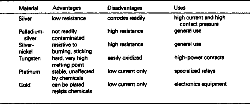
Silver contacts are desirable if the lowest possible contact resistance is needed for high-current use, but the action of the switch will have to be such that the contact pressure is high, and the contacts are wiped as they are brought together. Silver plated contacts can be used with fewer problems when the relay is sealed in such a way as to exclude atmospheric contamination, or if the contacts are surrounded by inert gases, but these are not simple solutions to the corrosion problem. Some relays are now available which use the compound silver cadmium oxide for contacts. This, being an oxide already, resists further oxidation, but has reasonably low resistivity and is fairly soft so that good contact can be made at low levels of holding force.
Gold plating is a very common solution to the contact problem, particularly for low-current electronics use. The contact resistance can be moderately low, and the gold film is soft, so that moderate pressure can result in a comparatively large area of contact. Of all metals, gold is about the most resistant to corrosion, although the combination of hydrochloric acid and electric current can cause gold to be attacked quite rapidly, making this material unsuitable if the atmosphere contains traces of chlorine or hydrochloric acid. Since passing electric current through sea-water causes chlorine to be generated, gold plated contacts can be severely corroded when the switches are used at sea. The contacts are suitable only for the lower currents, but since most relay applications in electronics are for low currents this is no handicap. Gold plating of contacts is often mandatory in the specification of switches for military contracts.
Contact coatings based on the ‘noble’ metals are often employed. These metals are so named because of their high resistance, like gold, to chemical attack, and typical metals in this group are platinum, palladium, iridium and rhodium. All of them have rather high contact resistance, but are very stable and resist chemical attack. Platinum is particularly useful for contacts that will be used for low currents and for high voltage levels. Rhodium and iridium platings provide a high level of resistance to corrosion along with stable contact resistance, and are suitable for medium voltage, medium current levels. Some advantages can be gained by using thick films of contact materials which are alloys of the noble metals with silver. For example, palladium–silver has a much better resistance to contamination than silver itself, although with a higher contact resistance than silver. It is one of the general contact materials that can be used in relays for various types of applications.
The metals tungsten and molybdenum, although not of the platinum group, are also used as contact materials for special purposes. Tungsten in particular is very resistant to melting caused by contact arcing, and is used for high power switching. Its disadvantage is that the surface will oxidize easily, causing contact-resistance problems. The most common general-purpose contact alloy material, however, is nickel–silver. The cost of nickel-silver is such that it can be used as a bulk material rather than as a coating, and although its contact resistance is higher than that of pure silver, it is much more resistant to chemical attack than the pure metal. It also resists burning and the contacts do not tend to stick together.
Where contacts can be hermetically sealed, mercury wetted contacts can be used. As the name suggests, the contact materials are amalgamated with mercury (meaning that the metals dissolve in the mercury) which softens the materials and makes it very easy to obtain a large contact area at low pressure, greatly reducing the contact resistance. Mercury wetted contacts also eliminate contact bounce (see later) and are extensively used in reed relays. Mercury wetting must never be used for open contacts because the mercury will evaporate, and the vapour is hazardous.
The make and break times for relays are often quoted. These are the times in milliseconds that are needed for a change in energization (coil switched on or off) to cause the contacts to change over. The make and break times (or operate and release times) are sometimes identical, but more often the make time is longer than the release time because the time for the collapse of the magnetic field is faster than the time to establish the field, and also because the make time includes the time for which the contacts bounce. Times of 5–20 ms are typical for the range of small relays used in electronics circuits.
• The release times can be improved where a relay is driven by a semiconductor circuit if a zener diode is used to catch the back-EMF, as illustrated in Figure 6.3.

Contact bounce is a problem that applies to any type of mechanical contacts. No simple mechanical contacts deliver a single voltage change as they close because the elastic nature of the contacts means that contacts will make, then bounce apart and remake at least once, delivering a multiple pulse. Contact bounce in analogue circuits will cause noise, mainly impulse noise, but in digital circuits it can cause total failure of the action, since if the closing of the contacts generates a signal, then bouncing will generate multiple signals. Digital circuits rely on counting the number of pulses rather than the voltage level of these pulses, so that the signals created by bouncing contacts amount to spurious signals in the system. Since the bounce is almost unavoidable (although mercury wetted reed switches, as noted above, are almost bounce-free) the methods that are used to eliminate the bounce must be electronic, using some form of debouncing circuit based on either a flip-flop or the use of a Schmitt trigger circuit.
An older use for relays is as a chopping device. In this application, the relay coil is switched at a mains frequency rate, typically 50 Hz or 60 Hz, and the contacts are connected to a steady voltage, so that the output is a square wave. This type of circuit was at one time used for such diverse purposes as supplying AC for car radios (when 100 V+ supplies were needed), or for DC amplification. The car radio applications called for a mechanically tuned self-oscillating type of relay, and switching noise (‘hash’) was always a problem. These types of applications became obsolete when semiconductor circuits replaced them.
Relay varieties
Conventional mechanical relays exist in a huge variety of forms, from sub-miniature types that are enclosed in metal cans of the same size as the TO-5 transistor casing, to heavy-duty types that require to be mounted on a steel chassis. Of this range, a few examples will be described in detail as an indication of what can be expected. The smallest relays in a TO-5 can are double-pole change-over types, which can be obtained with coils rated for 6 V, 12 V or 24 V, the standard relay operating voltages, along with a nominal currents of about 15 mA to 60 mA; the lower voltages require higher currents so that the power is constant at about 0.36 W. Contact ratings are typically 28 V, 1 A DC, with a mechanical life in excess of 107 operations. The operate and release times are each 4 ms, and the contact resistance is 100 mΩ. The capacitance between open contacts is quoted at 0.7 pF, making this type of relay very well suited for switching high-frequency signals. If you need to switch RF, you should look for a relay intended for this purpose, whose voltage standing-wave ratio (VSWR) is quoted.
Many types of relay are intended for direct mounting on PCBs, and a good example is the miniature double-pole change-over type. The usual range of voltages (6, 12, 24) is provided in three coil choices, with a working power dissipation of 0.7 W. The contacts are silver and rated at 30 V DC or 250 V AC at 5 A. Note the very large difference between the AC and the DC ratings, reflecting the effect of DC on arcing between contacts. The proof voltage is 2.5 kV 50 Hz AC, and the maximum ambient temperature is +55°C. The mechanical life is quoted as being in excess of 107 operations, with an electrical life in excess of 2 × 10⁶ operations at full rated load. The whole relay is protected with a clear cover.
Plug-in relays exist in a huge variety of types and sizes, but one very durable series has made use of the type of sockets that were once used for radio receiving valves. These relays use either 8-pin or 11-pin bases, and are also covered, using a clear polycarbonate material which can be removed if needed. This range of relays is available in the usual DC range of operating voltages, but also for 115 V DC, and in AC form for the voltages 12 V, 24 V, 48 V, 115 V and 230 V AC. The power rating for the DC types is 1.3 W, and for the AC types 3 VA. The contacts are rated at 30 V DC or 250 V AC at 10 A, with the contact material being gold-coated silver. Operate time is 15 ms maximum, and release time is 10 ms maximum. The test voltage is 2 kV at 50 Hz, and specified insulation resistance is 100 MΩ. Electrical life is quoted as being in excess of 106 operations, with mechanical life in excess of 107 operations. The ambient temperature limit is 65°C when the relay is working at nominal voltage, but only 35°C when the relay is used at its maximum permissible voltage of about 8% higher than nominal voltage. The ambient temperature can be as high as 105°C when the relay is kept unenergized.
A variation of these plug-in relays is a type with a test button and indicator system. Pushing the test button allows the contacts to be changed over manually, with a flag indicator showing that the contacts have, in fact, changed. In addition, a neon or LED indicator (depending on the relay voltage range) will indicate when the relay is energized. This type of relay can be employed usefully when relays are used only for emergency purposes and it is necessary to check the action at intervals and to know when the relay has been triggered.
Heavy-duty relays can be arbitrarily defined as relays which have contact ratings exceeding 10 A, and which are intended for bolting to a steel chassis. A typical heavy-duty 20 A relay has double-pole change-over (DPCO) contacts using silver and silver cadmium oxide surfaces. The 20 A rating applies to 20 V DC or to 240 V AC, and for AC contact operation, the electrical life is quoted as exceeding 104 operations. Coil operation can be DC, using 12 V or 24 V, with a power rating of 2.5 V. For AC operation, voltages are 110 V or 240 V, with a 3 VA rating (hold) and 5 VA to cause change-over (the inrush rating). This is by no means the largest current rating that can be obtained, but represents the highest current handling that would normally be considered in terms of electronics as distinct from electrical applications. Relay-like devices that handle appreciably larger currents and voltages are classed as contactors.
Having looked at these examples which are typical of the range of relays, we can also look at some less common types which are sometimes specified for equipment. The remanence or latching relay is a type that depends on the use of a core material that retains its magnetism to some extent. When current is passed through the coil, the contacts change over, and will remain in that condition when the current is broken. To change the contacts back again, a reduced amount of current has to be passed through the coil in the reverse direction. The manufacturer will specify a suitable value of resistor to connect in series with the coil when current is to be passed in the reverse direction. The remanence relay is a compact and reliable way of implementing a system in which one button is pressed to switch on and another to switch off, and Figure 6.4 shows a typical circuit. The maximum time for which current can be passed is important, and will be specified for a range of temperatures. Minimum time for applying current in either direction is of the order of 10 ms.
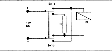
Figure 6.4 Remanence or latching relay circuit, using one button to close the relay and the other to open it.
The latching relay achieves the same type of action, but by using a permanent magnet and two separate coils. A voltage applied to a coil for at least 50 ms will cause the contacts to change over, and the contacts will remain in this set position until the other coil is activated for at least 50 ms. A latching relay is inevitably larger and more costly than its normal counterpart, but the same specifications as regards contact ratings, proof voltage, insulation resistance and life apply. The coils are usually rated for continuous operation although in practice they are energized only for brief intervals.
Relays can also be obtained with specialized contact systems. An example is the coaxial relay in which the contacts form part of a 50 Ω coaxial system, allowing a change-over action for signals at frequencies up to 450 MHz. The normal relay specifications apply here, and in addition the voltage standing-wave ratio (VSWR) is specified as better than 1.1:1, with cross-talk between the outputs at –39 dB.
For electronics purposes, many relays would be used in circuits where the coil operation was by current from a semiconductor device such as a transistor or IC. To obviate the need to build relay-driving circuits into the equipment, advantage can be taken of relays that incorporate driving circuits, transistorized relays. These are available as normal and high-sensitivity types, with the high-sensitivity types using a Darlington type of connection. The usual 12 V and 24 V operating voltages are used, but because of the use of transistors, the range of operating voltages can be very much larger, so that a nominal 12 V unit can operate with a voltage range of 5–25 V, though the advised variation is 11–13 V. The operating currents are in the range 5–10 mA for the standard type, and below 1 mA for the high-sensitivity type. The protecting diode is already wired across the coil, and since the input is to a transistor base circuit, no protection is needed for the driving circuit.
Although like transistorized relays they are not strictly speaking passive devices, solid-state relays can also be bought (as distinct from discrete thyristors). These are available in a set of standard packs, ranging from DIL, PCB and plug-in to surface mounting. A particular advantage is that no mechanical contacts are involved, so that DC ratings are quoted for currents up to 40 A, although they are not suited for very low DC voltages. The devices are particularly suited to switching AC loads, although for inductive loads a combination of a 100 Ω resistor and 0.1 μF capacitor is required with some types to suppress transients. A varistor wired across the output is also recommended for transient suppression in other applications. Some types need to be bolted to a heat-sink for use at full rated voltage and current.
Reed switches
Reed switches are widely used for signal switching, particularly at the lower signal frequencies. The main attraction of the reed type of switch is that the contacts are enclosed and therefore cannot be damaged in adverse environments. In addition, the switch is magnetically operated either by a solenoid coil or by a permanent magnet, so that remote control is possible and variable capacitance to the hand of an operator is not a problem. In this respect, the reed switch is normally used as a secondary switch or relay in the sense that the operating current to its coil will normally be controlled by another switch. Reed switches are generally classed as relays for the purposes of cataloguing electronic components.
The reed switch can therefore be mounted directly on a PCB deep inside the circuit, possibly in an inaccessible place, and operated from any conventional type of low-voltage switch on a panel. This avoids the problems of bringing a signal cable out to a panel-mounted switch and back again. Table 6.2 shows the international designations for reed relay contact arrangements in terms of Form A or Form C.
Table 6.2
Reed relay contact arrangements
| Form | Contacts | Abbreviation |
| A | single pole | SP |
| C | single pole change-over | SPCO |
| Double A | double pole | DP |
| Double C | double pole change-over | DPCO |
The basic reed principle is illustrated in Figure 6.5. The thin metal reeds are sealed into a glass tube, and bent so as to make contact because of the effect of a magnetic field. The usual arrangements of contacts are normally open or change-over, and the reed portion can often be specified separate from the actuating coil or magnet. The use of the solenoid coil allows relay type of operation, but the use of a permanent magnet allows mechanical operation (by moving the magnet to or from the reed tube) which can be custom-made to whatever pattern is needed. The typical magnet distances are of the order of 7–11 mm to operate the reed, 13–16 mm to release, so that a movement of around 5–20 mm would normally be used to ensure reliable opening and closing of the reed circuit. The predominant use of reeds, however, is with the solenoid, using up to 100 ampere-turns to operate the reed.
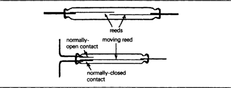
Figure 6.5 Reed relay principles. The thin nickel-alloy reeds are encased in glass and bent into contact by a strong external magnetic field.
One important feature of reed-switch use is the fast switching time. This will be of the order of 1–2 ms to make, and can be as low as 0.2 ms to break, with reed resonant frequencies in the order of 800–2500 Hz. Fast switching speed is not necessarily an important feature of signal switches, but if signals have to be sampled or if there has to be switching from one signal source to another at frequent intervals then the reed type of switch has considerable applications. An important further consideration for high-frequency or fast rise-time signals is the very low capacitance between open contacts, which can be less than 1 pF for the normally-open type of reed. The use of silver- or gold-plated contacts allows low contact resistance values of around 100 mΩ, and for applications that demand very low and stable contact resistance, mercury wetted reeds can be obtained. The mercury wetted type also has the advantage of providing very low-bounce operation, a point that will be taken up later. The normal dry contact type of reed is as prone to contact bounce as any other mechanical switching device.
The other features of reed switches are high insulation resistance (because of the use of glass encapsulation), of the order of 100 000 MΩ, and high breakdown voltage of at least 200 V.
• Beware of packaged units of reed switch and coil, because these are usually cased in nylon, which has a greatly reduced insulation resistance in humid conditions and at high temperatures.
The operating currents are also quite surprisingly high for a device with small contacts and limited contact force, of around 0.25–2 A. This is mainly because the reed type of relay does not permit a good magnetic circuit to be constructed; most reed operating coils make no use of any magnetic core material. Mechanical life, depending on type of use and reed construction, ranges between one million and one hundred million operations. Like any other form of contact device, the contacts need to be protected by a diode if they are to be used to switch current from an inductive load, and any device that switches the reed operating coil will also require this protection.
Solenoids
Solenoids are used to convert electrical energy into mechanical force, so that mechanical equipment can be electrically controlled. Solenoids can be obtained for mechanical action only, or ready coupled to devices like valves for liquid or gas control. The specifications for the general-purpose type of solenoids will include both electrical and mechanical ratings, and the solenoids can be classed according to the type of mechanical action as push–pull, lever or rotation.
Another concept that is not encountered for other components is duty cycle. Some solenoids may be required to operate continuously for long periods, so that their duty cycle is 100%. Others may operate only at intervals and for a short on time, so that a solenoid that was activated for 30 seconds in each 5 minutes would have a 10% duty cycle. The ratings of a solenoid include allowances for different duty cycles, so that higher voltages can be applied, if required, to solenoids whose action is subject to a low duty cycle.
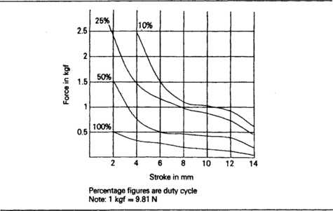
Push–pull solenoids are available as DC (12 V or 24 V) or AC (110 V or 240 V) operated devices, with a specified coil dissipation such as 10 W or 11 VA for a 100% duty cycle. The amount of force that can be exerted then depends on the stroke (the amount of mechanical movement) and the duty cycle, assuming that the maximum operating voltage will be used for each value of duty cycle. These relationships are not simple, and are best expressed in graphical form as Figure 6.6 illustrates. The mechanical equipment that is operated by the solenoid should be arranged so that the combination of force and stroke that the solenoid can deliver will be suitable. The fact that the maximum of force can be delivered at the start of an action (when the stroke is negligibly small) means that the solenoid is well equipped to overcome initial friction. One point to note is that if AC operation is used, the mechanism must not be capable of stalling; the armature must always be able to travel fully into the solenoid, otherwise an excessive current will be drawn.
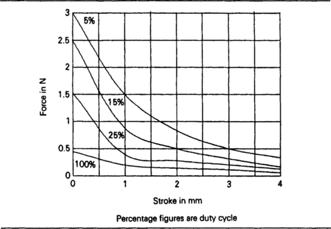
Lever solenoids are based on relay construction, and are often little more than a relay from which the contacts have been removed, leaving the armature and the frame. These types of solenoids are intended for a range of lower forces and strokes, as illustrated in Figure 6.7. Like a relay, lever solenoids are equipped with a return spring, although this can be removed if there is a spring action in the mechanism that the solenoid is operating.
The rotary type of solenoid produces torque rather than force, but has the same form of graph of torque plotted against rotation for each value of duty cycle. Spring return is normal, but the spring can be removed if there is any other way of rotating the shaft back when the coil is de-energized. The maximum stroke is of the order of 45°.
Motors and selsyns
Even a fraction of the vast range of electric motors cannot necessarily be regarded as being electronic components, and in this respect, only these motors which will be actuated by electronic circuits can be considered. Of these, the miniature general-purpose DC motors, using permanent magnet fields, can be included on the grounds that with voltage requirements of 6–12 V and currents of 20–400 mA they can be controlled by the output from a comparatively low-dissipation semiconductor amplifier. Small electric motors of this type can be used in models, rotating signs, display systems and to some extent in robotics.
A much more important type of motor, however, is the servo type of motor which is intended to run in conjunction with a tachogenerator or a potentiometer as part of a closed loop system in which the potentiometer or tachogenerator provides one input to a comparator amplifier (Figure 6.8). A servomotor for this type of application should have a rotor with a very low moment of inertia so that rapid starting and stopping can be achieved. This points to the use of an ironless rotor, with the additional advantage that with no high-permeability materials in the rotor there is no tendency for the rotor to stop in preferred positions (called ‘cogging’) or to have difficult starting positions. In addition, the motor runs more smoothly when it is free of the alternate strong and weak forces that occur as the poles of an iron rotor revolve. The use of precious metals in the commutator and the brushgear also makes for operation at much lower voltages than the conventional carbon-brush type.
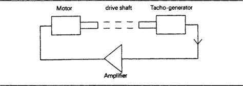
Figure 6.8 A simple servo system. The motor, mechanical connection, generator and amplifier constitute a negative-feedback loop.
Any DC electric motor functions as a DC generator as its rotor revolves, and a motor will reach a stable speed when the back-EMF plus the voltage drop across the resistance of the rotor coil equals the applied voltage. For a motor with a permanent-magnet field or a parallel (shunt) field winding, this means that the speed of the motor is to some extent self-regulating, because when the motor is loaded, the speed will drop, lowering the back-EMF and allowing more current to flow through the rotor coil in order to provide more power. For small servo motors, the back-EMF can be calculated by using figures provided by the manufacturer. One such figure is the EMF constant, which is defined as the back-EMF per 1000 rpm rotational speed. This is usually simpler to work with than the EMF per radian per second factor that is used in textbooks. The EMF constant is usually equal to the rated voltage divided by the no-load speed in kilo-revs per minute.
The parameters that are measured for a servomotor are illustrated in Table 6.3, along with a set for a typical 12 V motor. Most are concerned with the torque and the speed of the motor, but there are two thermal constants, the thermal time constant and the thermal resistances. The thermal time constant is the time in seconds for the rotor or stator to reach 63% of its final temperature for a given amount of dissipated power. Like resistor–capacitor time constant, this implies that the motor parts will reach their final temperature in about four time constants, so that for a 7 second thermal time constant, final temperature will be reached in 28 seconds. The stator time constant for a conventionally constructed motor that uses a massive stator and a light rotor will be very much longer, of the order of 9 minutes. The thermal resistances are expressed in the usual units of °C/W, so that the rise in temperature per watt of dissipation can be calculated. These assume no form of heat-sink.
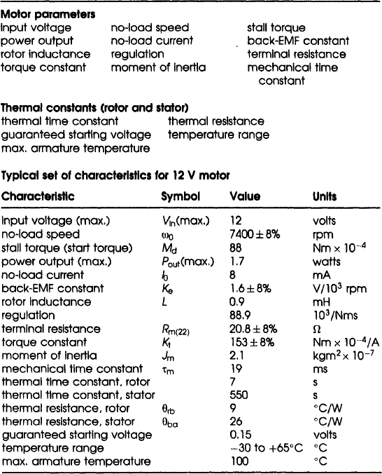
Temperature is particularly important for servomotor operation, because quantities such as the current for zero-load depend very heavily on temperature. Stall torque and armature resistance have a temperature coefficient value of about 0.4%/°C (positive for resistance, negative for stall torque). The most important calculation is the power requirement, taken from measurements on the load that the motor is to drive. If the power required is not within the capability of the motor a larger motor will have to be used, or the mechanical part of the system will have to be redesigned. Table 6.4 shows some of the basic motor equations and the steps that are required in calculating the current that a small motor will take. For details, the manufacturer of a suitable motor should be consulted.
Table 6.4
The main motor equations and the steps in determining the choice of motor size and calculating operating conditions
| Voltage, current and speed – | V– applied voltage |
| V = IR + Kψ | I – rotor current |
| Power input – | R– terminal resistance |
| P = Mψ | K– torque constant |
| Electrical power dissipated – | ψ – rotational speed |
| P = I2R | M –torque |
Steps in designing servomotor applications:
1 Determine torque required for load. If this exceeds 50% of stalled torque for motor, a reduction gearbox will be needed.
2 Knowing load speed required, calculate power. Choose motor to suit this level of power.
3 Calculate watts dissipated in motor.
5 Calculate temperature rise from thermal resistance figure.
Whereas the servomotor is a DC device, the selsyn (or synchro) is an AC device which depends on phase differences. The principle is illustrated in Figure 6.9. The rotor is a single-phase winding revolving inside a three-phase stator, and the construction for both transmitter and receiver is identical. In use, both rotors are energized from the same AC source (often from an inverter so that the supply is at 1 kHz), and the stator phase leads are connected together. Once energized, the two rotors will take up positions that correspond one with the other, and revolving one rotor (the transmitter) will result in the other rotor (of the receiver) also revolving at the same rate. The two rotors will remain perfectly in step as long as the torque loading on the receiver is negligible, but if the receiver has to drive any significant load, there will be an angular error whose amount depends on the size of the machines and the amount of loading.
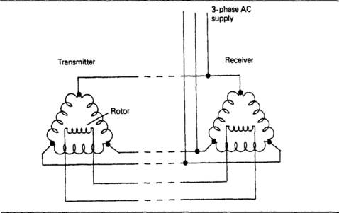
Selsyns do not provide the same amount of precision as a servomotor system, nor can they provide the same driving torque, but their simplicity, with no brushgear, no amplification and no solid-state components, makes them very attractive to some light-load applications. One notable use of the principle was to radar displays in which the revolving aerial drove the rotor of one selsyn and the stator coils at the receiving end were used as the deflection coils of a CRT whose display was of a line. As the aerial rotated, the rotating field at the deflection coils caused the line scan of the CRT also to rotate, generating a circular scan (the plan-position indicator (PPI) scan).
Another electromechanical device in the motor family is the stepping motor. As the name suggests, the shaft of a stepper motor will rotate by a fixed angle for each input, and combinations of stepping motor and lead-screw drive can be used to provide linear steps in place of steps of rotation.
The principle of stepper motors is multiphase drive, and a typical stepper would normally use a four-phase set of windings. The stepping action is achieved by pulsing the four windings in sequence, using pulses derived from an IC driver. For example, if the four windings are L1, L2, L3 and L4, then a typical sequence would be:
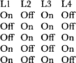
Note that two windings change in each step. The cycle as shown here repeats after four steps, and each step would typically take the shaft through 1.8°, so that fifty repetitions of this pattern would turn the shaft through a full revolution.
Stepping motors are usually operated at low voltages, 3 V or 5 V DC, and with fairly low currents in the range 100 mA to 2 A. The driver circuits will need to use heat-sinks, however, and very great care must be taken to ensure that none of the leads to the motor becomes disconnected while the other leads are carrying pulses, as this will always cause serious damage. Although the average currents are fairly low, the peak currents in each pulse can be large, so that wire of at least 24/0.2 size needs to be used between the driver board and the motor. If large torque values are required with smaller steps, gearboxes can be attached, but precision would be lost if this is done because of the inevitable backlash in the gearbox.
Magnetic clutches
The magnetic clutch is a useful electromagnetic component which is rather more specialized than most of the components which have been described in this book, and is not usually listed among electronic components. The principle is that a mechanical drive can be made or interrupted by the clutch according to the state of an electrical supply and for the miniature types of magnetic clutch the two main methods of action are powder or liquid. In either case, the action is very similar – two magnetic disks face each other and a magnetic powder or liquid is placed between them.
One disk is connected to a shaft which is powered, and the other disk is connected to an independent shaft, the driven shaft. The whole assembly is surrounded by an energizing coil. When the coil is unenergized, the powder or liquid transmits very little torque to the driven shaft. How much torque is transmitted in this state depends on the packing of the powder or the viscosity of the liquid. When the coil is energized, however, the powder or liquid starts to behave as a solid, locking the disks together so that the driven shaft is to all intents and purposes connected directly to the driving shaft. The torque that can be transmitted is considerably increased if the disks have small blades rather than being completely smooth.
Magnetic clutches offer a fast and smooth take-up of a mechanical drive without the need to start and stop a motor, with all the attending problems of current surge. Characteristics of magnetic clutches vary widely, some are designed to be on/off devices, with no real ‘slipping’ state, others are intended to allow an amount of slip that varies according to the energizing of the coil. One attraction of the system is that a magnetic clutch system driven by an AC motor offers a variable-speed drive system that does not depend on DC motors nor on the use of thyristors.
AC motors can now be obtained with variable-speed driving circuits. These use either variable frequency, variable pulse width, or a combination of both methods, and are widely available.
Filters and suppressors
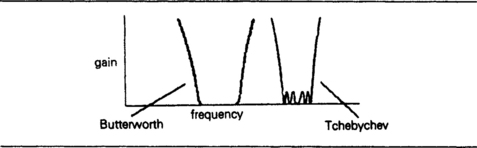
A filter is a device which will conduct (pass) one band of frequencies and reject others, the frequencies of the stop-band or attenuation band. An ideal filter would not attenuate signals in the pass-band and would cause infinite attenuation of all signals in the stop-band, with a sharp division between the bands at a frequency called the cut-off frequency. On this basis, the idealized filter characteristics for the main filter types would be as shown in Figure 6.10.

Purely passive filters can be constructed from combinations of inductors and capacitors (LC filters), and from combinations of resistors and capacitors or resistors and inductors. Filters (of very precise characteristics) can also be made using active semiconductor devices such as op-amps, switched capacitors and SAW devices; all beyond the scope of this book.
The use of resistors in a filter, however, means that there will be considerable attenuation in the pass-band, and no sharp separation between pass-band and stop-band, so that RC and RL filters are useful mainly when they are used in conjunction with semiconductors as active filters. The closest approach to ideal filtering is achieved by transducers of the surface-wave type, noted in Chapter 8. Filters can be low-pass, high-pass, band-pass or band-stop, as indicated in Figure 6.10.
The use of inductors and capacitors in filters gives rise to much more complicated response curves than the ideal shapes of Figure 6.10. In addition, the calculation of filter response and of the sizes of components is far from simple. Fortunately, computer software is available for filter calculations, and can be downloaded from several sources on the Internet – use a search engine of your choice to find a phrase such as filter calculations.
The two main types of response for a ladder network filter are called Butterworth and Tchebycheff (also spelled as Tchebychev or Chebycheff) respectively. The differences are that the Butterworth response shows very little variation of attenuation in the pass-band, but the transition between pass-band and stop-band is not particularly steep. The Tchebycheff response shows more variation within the pass-band, but has a steeper slope between the bands (Figure 6.11). There is no difference in circuitry needed to provide the responses of these filters – the same filter circuit can be made to provide either form of response depending on the values of the components.
The two basic arrangements of components for a ladder network are T and Pi, illustrated in Figure 6.12. Either of these can be considered as being made out of half-sections, as illustrated, so that the construction of each half-section is the main factor in the design of a filter. Using inductors and capacitors, the half-section consists of a series and a shunt element, two reactive elements, so that the simplest type of filter is a two element type, but most practical filters use more than two elements in the half-section so as to achieve better performance.
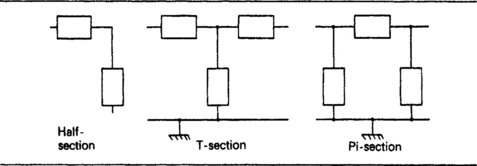
Figure 6.12 The T and Pi arrangements for filter sections. Each can be considered as made up from half-sections.
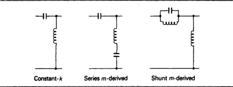
Figure 6.13 shows the simplest low-pass filters, called the constant-k, series m-derived and shunt m-derived types. The k refers to the geometric mean impedance, the root of the product of input and output impedances for the half-section, and m refers to the quantity:
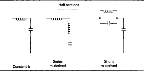

where fc, is the cut-off frequency and f∞ is the frequency of peak attenuation.
Even for these comparatively simple elements, the prediction of response is anything but easy, because each half-section is supposed to be connected to an impedance which matches its own (variable) impedance. In addition, expressions for the filter behaviour are often based on idealized lossless inductors and capacitors. This makes it all the more difficult to draw out the behaviour for a ladder network of several sections (Figure 6.14), in which the elements will inevitably interact.
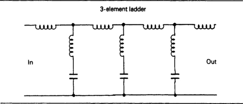
Figure 6.14 An example of a complete ladder network, for which calculations are lengthy and best done by computer.
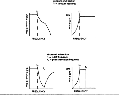
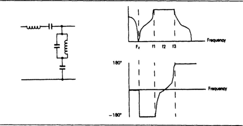
The response curves for full sections of low-pass filters are illustrated in Figure 6.15, showing idealized attenuation and phase characteristics in terms of cut-off frequency and peak attenuation frequency. Note that the constant-k type of filter has its frequency of peak attenuation at a theoretically infinite frequency, whereas the m-derived types have an attenuation that reduces at frequencies beyond the peak. Figure 6.16 shows high-pass filter sections, once again using the constant-k, series m-derived and shunt m-derived forms. The performance curves for full sections are illustrated in Figure 6.17.

Band-pass and band-stop filters will usually incorporate more elements than a high-pass or low-pass type, and Figure 6.18 shows a five element series type of band-pass filter along with the full-section responses. Filters of this complexity are seldom nowadays constructed with passive components because the behaviour of active filters and of the SAW type is so much more predictable and so much closer to ideal performance.
Two important filter types make use of resistor and capacitor networks. Figure 6.19 shows the twin-T network (a), with typical response curves for amplitude and phase (b), and Figure 6.20(a) shows the Wien bridge with its frequency and phase response curves in (b). Both examples have used as frequency determining components values of 10 nF and 10 kΩ, but note that the twin-T network requires one capacitor of double the 10 nF value and one resistor of half the 10 kΩ value. These two networks have been extensively used in oscillator circuits and in ‘notch’ filters, but generally in the frequencies below 100 kHz.
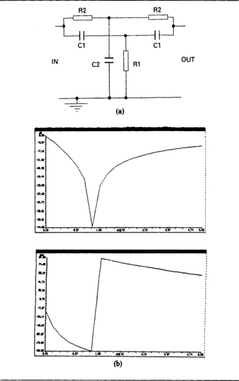
Figure 6.19 The twin-T notch filter circuit (a), with its frequency and phase response graphs (b). The values used are R1 = 5 kΩ, R2 = 10 kΩ, C1, C2= 10 nF.
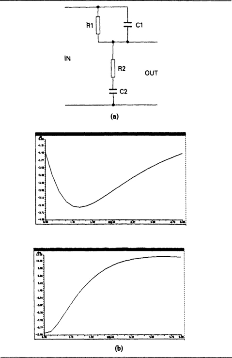
Figure 6.20 The Wein bridge notch filter circuit (a) with its frequency and phase response graphs (b). The values used are R1, R2 = 10 kΩ and C1, C2 = 10 nF.
A delay line is a form of low-pass filter whose phase characteristics are more important than the attenuation characteristics. The aim is to cause the time delay of a signal (often a pulse or other non-sinusoidal signal) by times of up to a microsecond or so. Since the delay line is a low-pass filter, it will cause unavoidable attenuation, so that delays of more than about a microsecond involve so many sections of line that the attenuation is too large for practical use. For longer delays, transducer delay lines of the acoustic type (see Chapter 8) are preferred.
Suppressors are a special case of filters of the band-pass type, in which some variation of the attenuation in the pass-band can be accepted in exchange for high attenuation in the stop-band. The pass-band is often wide, covering the radio and/or TV range of frequencies, with high attenuation particularly at the lower frequencies. The design methods are as for filters generally, but some forms of suppression use non-linear resistors in addition to inductors and capacitors.