Chapter 6. IP Management Plane Security
In this chapter, you learn about the following:
• Different types of management interfaces of IP routers
• Different access methods to IP routers
• Security techniques to secure the IP management plane
• Management of MPLS VPN customer edge routers using a secure Management VPN
As described in Chapter 1, the management plane is used to provision, manage, and monitor IP networks, as well as individual network elements. This also includes the configuration of the many security techniques detailed throughout this book. Because the management plane enables network provisioning and telemetry, it is critical that:
• Management plane resources and protocols are secured to mitigate the threat of unauthorized access and malicious network reconnaissance, which inevitably leads to attacks within the IP data, control, and services planes
• Management plane resources within an IP router are protected to mitigate the risk of DoS attacks, because most management plane packets are handled at the Cisco IOS process level
• Management plane resources remain available during attacks such that attack sources can be identified and attacks themselves can be mitigated
The many threats against IP networks were described in Chapter 2, “Threat Models for IP Networks.” This chapter describes techniques available to mitigate threats associated with the management plane. Data plane techniques such as infrastructure ACLs also help to protect the management plane, given that authorized management plane protocol traffic is generally limited to well-known, trusted, and internal sources. As described in Chapter 4, “Data Plane Security,” infrastructure ACLs prevent unauthorized external traffic from gaining IP reachability to internal network infrastructure, including IP edge router addresses used for internal management plane protocols. This chapter also assumes that the network is physically secure. Network-based security measures become ineffective if physical security has been breached. The techniques described in this chapter also apply to multilayer Ethernet switches running IOS (subject to IOS release and platform-specific dependencies) and to routers configured for IPsec VPN services. Hence, a separate review for those topics, as was presented in earlier chapters, is not provided here. Conversely, specific management plane considerations for MPLS VPNs are described in this chapter. Chapter 7, “Services Plane Security,” will review techniques to secure and mitigate attacks within the IP services plane.
No single technology (or technique) makes an effective security solution. This applies not only to IP networks but also to the individual IP traffic planes. Following the defense in depth and breadth principles outlined in Chapter 3, “IP Network Traffic Plane Security Concepts,” you may consider deploying multiple complementary techniques, including those described in this chapter and those described in earlier chapters, to mitigate the risk of management plane attacks.
Management Interfaces
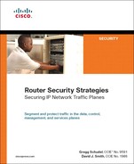
As described in Chapter 1, “Internet Protocol Operations Fundamentals,” one of the strengths of the IP protocol is that all packets are carried in a common pipe (also referred to as “in-band”). Legacy networks based on TDM, Frame Relay, ATM, and so forth typically relied on separate communications channels for data and control traffic. IP does not segment its traffic planes into separate channels. Thus, a router must look at every single packet entering an interface and decide what type of packet it is—data, control, management, or services plane—and apply the appropriate processes to each packet based on this determination. IP management plane packets are handled in-band with all other IP traffic. Although this is the native behavior of the IP protocol as defined within the IETF industry standards, many network operators build separate, out-of-band (OOB) management networks dedicated to carrying management plane traffic. The in-band and out-of-band management interface types are illustrated in Figure 6-1 and described further here:
Figure 6-1. In-Band and Out-of-Band Management Architecture
• In-band management interface: A physical (or logical) interface that carries both management and data plane traffic. An IP network that is managed in-band shares its physical facilities (that is, network links) and data plane (and the control plane and services plane) with management plane traffic. An in-band management interface is also referred to as a shared management interface. As described in Chapter 1, transit management plane traffic is processed in the CEF fast path by intermediate routers, just like data plane traffic. Management applications that operate in-band may use any of a router’s interfaces or IP addresses for management connectivity. Loopback interfaces are commonly used as the in-band management interface (or IP address) because they are always up, unlike physical interfaces (provided the router itself is alive). Physical interfaces used for in-band management connectivity have no distinguishing characteristics. Any physical interface used for data plane forwarding may also be used for in-band management. To dedicate an in-band physical interface for OOB management, refer to the “Management Plane Protection” section later in the chapter.
• Out-of-band management interface: A physical interface that connects to a physically separate, isolated network dedicated exclusively to the operation and management of all network elements. An Out-of-band (OOB) network uses separate physical facilities (that is, network links, switches, and routers) and a separate control plane to carry management plane traffic to and from all network elements within the primary in-band network. Many SPs use separate, OOB management networks, which are commonly referred to as data communications networks (DCN). While such OOB networks have their own control planes, they are used exclusively for network management purposes. They never carry data plane traffic and isolation from data plane traffic within the in-band network is assured through the use of a separate control plane and separate physical network infrastructure. OOB management networks are deployed today for two primary reasons. The first is availability: an OOB network provides an alternate path to reach network elements if in-band management connectivity is lost. Note, you may design the OOB management network as the primary management path and use the in-band management path as backup. DCN designs vary widely. The second reason to deploy an OOB management network is for large-scale network management operations, including service provisioning, monitoring, billing, alarms, software upgrades, configuration backups, and so on. The following router interfaces are commonly used for OOB management:
— Console port: The console port (CTY) is an asynchronous serial port that uses a DCE RJ-45 receptacle for connecting a data terminal (DTE). Any devices connected to this port must be capable of asynchronous transmission.
— Auxiliary port: The auxiliary port (AUX) is also an asynchronous serial port but uses a DTE RJ-45 receptacle for connecting a modem or other DCE device (such as a CSU/DSU or another router) to the router. Any devices connected to this port must also be capable of asynchronous transmission. Unlike the console port, the asynchronous auxiliary port supports hardware flow control and modem control.
— Management Ethernet port: On certain routers, a separate Ethernet port is made available strictly for OOB management connectivity. CEF is disabled by default to prevent traffic forwarding between the OOB network and the in-band network. Cisco strongly recommends against enabling CEF routing functions on this port to prevent IP reachability between the in-band and OOB networks. With CEF enabled, an in-band network failure may cause in-band data plane traffic to be inadvertently rerouted across the OOB management network. In this scenario, the OOB network no longer exclusively carries management plane traffic, as intended.
Example 6-1 illustrates the four main types of management lines, as found by using the show line command.
Example 6-1. IOS show line Command Sample Output
Router# show line
Tty Typ Tx/Rx A Modem Roty AccO AccI Uses Noise Overruns
* 0 CTY - - - - - 0 0 0/0
1 TTY 38400/38400 - inout - - - 0 0 0/0
2 TTY 38400/38400 - inout - - - 0 0 0/0
3 TTY 38400/38400 - inout - - - 0 0 0/0
4 TTY 38400/38400 - inout - - - 0 0 0/0
5 TTY 38400/38400 - inout - - - 0 0 0/0
6 TTY 38400/38400 - inout - - - 0 0 0/0
7 TTY 38400/38400 - inout - - - 0 0 0/0
8 TTY 38400/38400 - inout - - - 0 0 0/0
9 AUX 9600/9600 - inout - - - 0 0 0/0
10 VTY 9600/9600 - - - - - 0 0 0/0
11 VTY 9600/9600 - - - - - 0 0 0/0
12 VTY 9600/9600 - - - - - 0 0 0/0
13 VTY 9600/9600 - - - - - 0 0 0/0
14 VTY 9600/9600 - - - - - 0 0 0/0
Console (CTY) and auxiliary (AUX) ports were described in the preceding list. VTY lines, as aptly named, are virtual terminal lines with no associated physical interface. They are used exclusively for remote terminal access, including inbound Telnet and Secure Shell (SSH) connections. VTY lines appear as line vty within the IOS configuration. By default, an IOS router has five VTY lines, numbered 0 through 4 (for example, line vty 0 4). However, you can create additional VTY lines by using the line vty command in global configuration mode. For more information on SSH, refer to the “Remote Terminal Access Security” section later in the chapter.
TTY lines represent standard asynchronous lines, which are separate from the console and auxiliary ports and the VTY lines. TTY lines are used for inbound or outbound modem and terminal connections and appear as line {line-number} within the IOS configuration. The specific line numbers are a function of the asynchronous interface hardware built into or installed within the router. TTY lines are often used to connect to the console ports of other devices or to connect to external modems for dial-in/out access.
By default, no password is defined for either the console or auxiliary parts. Hence, by connecting to a CTY or AUX line with the default IOS configuration, you are automatically placed into user EXEC mode. Conversely, VTY lines require a password (by default) to gain access to user EXEC mode. EXEC mode is the IOS software command interpreter. It interprets the commands you type and carries out the corresponding operations. By default, the IOS software command-line interface (CLI) has two levels of access to commands: user EXEC mode (privilege level 1) and privileged EXEC mode (privilege level 15). Level 1 provides the lowest EXEC mode user privileges and allows only user-level commands available at the router> prompt. Level 15 includes all enable-level commands at the router# enable prompt. You can use the privilege command in global configuration mode to configure additional privilege levels at which operators may log in, to allow or deny access to specific commands. The privilege command specifies the commands accessible at various levels. Up to 16 privilege levels can be configured, from level 0, which is the most restricted level, to level 15, which is the least restricted level. Which commands are available is based on your user privilege level. By default, there are only five commands associated with user privilege level 0: disable, enable, exit, help, and logout. You can display the commands available to you by typing a question mark (?) at the EXEC prompt. Screen output may vary depending upon your hardware and IOS software release. For more information on IOS CLI privilege levels, refer to the references listed in the “Further Reading” section.
Password Security
The use of password protection to control or restrict terminal access to the IOS CLI of your router is a fundamental element of router security. The following techniques enable you to control who is allowed access to the router and what IOS privilege levels they are granted once they gain access:
• password (line configuration): To specify a password on a line, use the password command in line configuration mode. A line is a console port (CTY), auxiliary port (AUX), virtual terminal (VTY), or asynchronous (TTY) line as described in the previous section.
After specifying a password on a line using the password command, you must activate password checking at login using the login command in line configuration mode. Example 6-2 illustrates how to enable password security on each of the available lines. The password and login commands are widely available within IOS.
Example 6-2. Enabling Password Security on Lines
Router(config)# line con 0
Router(config-line)# password s3cr3t
Router(config-line)# login
Router(config-line)# line 1 8
Router(config-line)# password s3cr3t
Router(config-line)# login
Router(config-line)# line aux 0
Router(config-line)# password s3cr3t
Router(config-line)# login
Router(config-line)# line vty 0 4
Router(config-line)# password s3cr3t
Router(config-line)# login
Authentication, authorization, and accounting (AAA) and Role-based CLI Access are also available and are described in their corresponding sections later in this chapter.
• username password: The password command described above specifies a password for a specific line. Using the configuration in Example 6-2, any user that attempts to connect to a line must enter the configured line password to be granted user EXEC mode access. To establish local username-based password authentication, use the username command in global configuration mode. After specifying a username password, you must activate username-based password checking for the lines using the login local command in line configuration mode. The username command is widely available within IOS.
• enable password: To set a local router password to restrict access to the various EXEC mode privilege levels, use the enable password command in global configuration mode. By default within IOS, no enable password is defined, and entering the enable command in user EXEC mode automatically places you into privileged EXEC mode level 15, which is the least restricted level. The enable password command provides an optional [level {level}] argument that may be specified to define a unique enable password per EXEC mode privilege level. If the level argument is not specified within the enable password command, the privilege level of the configured enable password defaults to level 15. Only authorized users who need privileged EXEC mode access should know the enable password. As stated in the preceding section, you may use the privilege command in global configuration mode to specify commands accessible at various levels. To specify the default privilege level for a line, use the privilege level command in line configuration mode. The enable password command can also be specified with either one of two types of passwords. The first, Type 0, is a clear text password visible to any user who has access to privileged mode on the router or who can access the configuration. The second, Type 7, is a password with a weak, exclusive-or based encryption scheme. Type 7 passwords can be reversed from the encrypted form by using publicly available tools. Its benefit is mainly in preventing shoulder surfers from viewing clear text passwords. The enable password command is widely available within IOS.
• enable secret: To specify an additional layer of security over the enable password command, use the enable secret command in global configuration mode. The enable secret command provides better security by storing the configured enable secret password using a nonreversible cryptographic hash function, compared to the enable password command, which stores the configured password in clear text or in an easily reversible encrypted format (described in the enable password text above). Storing the password as a cryptographic hash helps to minimize the risk of password sniffing if the router configuration file is transferred across the network, such as to and from a TFTP server. It is also useful if an unauthorized user obtains a copy of your configuration file. Note, if neither the enable password command nor the enable secret command is configured, and if there is a line password configured for the console port, the console line password will serve as the enable password for all VTY lines, which includes Telnet, rlogin, and SSH connections. The enable secret command is widely available within IOS. Username passwords may also be stored in the router configuration file in cryptographic hash format, similar to the enable secret. The associated command is username secret.
• security passwords min-length: To ensure that all configured passwords are a specified minimum length, use the security passwords min-length command in global configuration mode. The IOS default is six characters. This command affects line passwords, username passwords, enable passwords, enable secrets, and username secrets. After this command is enabled, any newly configured passwords that are less than the specified minimum length will be rejected within EXEC mode. This command is available in IOS 12.3(1), 12.2(27)SBC, and later releases.
• security authentication failure rate: To configure the number of allowable unsuccessful login attempts, use the security authentication failure rate command in global configuration mode. The default number of allowable failed login attempts before a 15-second EXEC mode delay is ten. This command also activates the generation of system logging (syslog) messages if the number of allowable unsuccessful login attempts is exceeded. This command is available in IOS Software releases 12.3(1), 12.2(27)SBC, 12.3(7)T, and later releases. For more information on syslog, refer to the “Network Telemetry and Security” section later in the chapter.
• service password-encryption: To encrypt local router passwords, use the service password-encryption command in global configuration mode. This command applies to line passwords, username passwords, enable passwords, and authentication key passwords, including routing authentication passwords and key strings. By default, IOS does not encrypt passwords. Encrypting passwords in this way helps to minimize the risk of password sniffing if the router configuration file is transferred across the network such as to and/or from a TFTP server. It is also useful if an unauthorized user obtains a copy of your configuration file. This command is widely available within IOS. It should be noted that this command invokes the same Type 7 encryption algorithm described earlier in this list.
This section reviewed the basics of IOS password security. The techniques described provide local authentication whereby password storage and authentication is handled locally on the router. IOS also offers a variety of login enhancements, including delays between successive logins, login shutdown if an attack is suspected, and syslog generation for each successful or failed login attempt. For more information on these login enhancements and the password security commands described in this section, refer to the IOS Configuration Guides and Command References available on Cisco.com.
Further, using strong-password creation techniques can greatly reduce the risk of unauthorized access. These techniques include the use of mixed-case letters, numbers, and punctuation symbols. Avoid using dictionary words, names, phone numbers, and dates. Better passwords are greater than eight characters and include at least one of each of the following: lowercase letters, uppercase letters, digits, and special characters. For additional information on choosing a secure password, refer to the US-CERT Cyber Security Tip ST04-002, “Choosing and Protecting Passwords,” available at http://www.us-cert.gov/cas/tips/ST04-002.html. For guidance on strong passwords, also refer to your organization’s own security policy. As referenced earlier in this section, AAA and Role-based CLI Access are described in their respective sections later in the chapter.
SNMP Security
The Simple Network Management Protocol (SNMP) is an application layer protocol that facilitates the remote administration of network devices. SNMP operates between SNMP managers and SNMP agents. SNMP managers request management-related information of, and receive unsolicited management-related messages from, SNMP agents. Conversely, SNMP agents respond to SNMP manager requests and send unsolicited messages to SNMP managers. Some SNMP-enabled devices support the functions of both an SNMP manager and SNMP agent. Such devices are referred to as SNMP proxies. IOS routers generally operate as SNMP agents.
The SNMP request messages referenced in the preceding paragraph include solicited get and set messages with which the SNMP manager requests and modifies, respectively, the value(s) of object(s) managed by an SNMP agent. Similarly, the SNMP unsolicited messages include trap or inform messages with which the SNMP agent provides an unsolicited notification or alarm message to the SNMP manager relating to a managed object. The primary difference between the trap and inform messages is that the inform message is acknowledged by the SNMP manager. A collection of managed objects is organized into a Management Information Base (MIB). A wide variety of MIBs have been defined as IETF industry standards. In addition, all vendors, including Cisco, define private MIBs in addition to the generic IETF MIBs for managing vendor-specific network elements and functions. For more information on MIB support for a given IOS platform and/or release, refer to the MIB Locator available on Cisco.com at http://tools.cisco.com/ITDIT/MIBS/servlet/index.
All SNMP messages are transported over the User Datagram Protocol (UDP). Solicited operations are sent by the SNMP manager to the UDP destination port 161 on the SNMP agent. Unsolicited operations are sent by the SNMP agent to the UDP destination port 162 on the SNMP manager. The acknowledgement sent by the SNMP manager to an SNMP agent in reply to an inform operation is sent to a randomly chosen high UDP port that is determined when the SNMP agent process is started. As such, the SNMP agent process in IOS listens for SNMP operations on UDP ports 161, 162, and the random UDP port selected. The SNMP process is started within IOS either at the time the device boots or when SNMP is configured.
Many router configuration parameters are available through SNMP managed objects, including but not limited to enable passwords. Therefore, it is critical that if the SNMP process is enabled, it be secured. SNMP is disabled by default within IOS. Nevertheless, it is the primary and most widely deployed protocol for remote management of network devices. The following techniques are available to mitigate the risk of SNMP-based security attacks:
• Community string: An SNMP community string is included within each SNMP protocol message and functions much like a password. The SNMP agent authorizes SNMP messages received using the associated community string. Community strings may also be applied to unsolicited messages sent from an SNMP agent to the SNMP manager. Knowledge of an SNMP agent’s community string provides access to all of its managed objects. To set the community string for the IOS SNMP agent and, thereby, restrict access, use the snmp-server community command in global configuration mode. Within this command you may define two different types of community strings: read-only (ro) and read-write (rw). Using the optional ro command argument, you can define a read-only community string, which provides read-only access to all of the device’s managed objects. Management stations authorized for read-only access can retrieve only MIB objects. Using the optional rw command argument, you can define a read-write community string, which provides read-write access to all of the device’s managed objects. Management stations authorized for read-write access can both retrieve and modify MIB objects. The strong-password creation techniques outlined earlier in the “Password Security” section should also be considered when you chose SNMP community strings. Note that no technique is available to encrypt or hash the assigned community strings within the router configuration file. Therefore, to reduce the risk of unauthorized access, you must restrict access and distribution of your router configuration files to protect your SNMP community strings and other router configuration information that can be leveraged for a security attack. Also note, SNMP community strings are transmitted in clear text across the IP network. More information on SNMP encryption is provided later in this list.
• Community string ACLs: The snmp-server community command described above also provides an optional {access-list} command argument. This allows for a numbered or named standard ACL to be specified in conjunction with the configuration of the community string(s) and is analogous to the protocol-specific ACL filters described in Chapter 5, “Control Plane Security.” The community string ACL restricts the source IP addresses that are allowed access to the SNMP process. SNMP packets received from hosts not permitted within the ACL are silently discarded. Note, this ACL filter is applied at the IOS process level within the SNMP agent itself. Unauthorized SNMP management hosts should also be filtered within your infrastructure ACL, IP rACL, and/or CoPP policies, as described in Chapters 4 and 5. When deployed in combination, along with antispoofing protection, each of these data, control, and management plane security techniques supports the defense in depth and breadth principles outlined in Chapter 3.
• snmp-server packetsize: As outlined in Chapter 2, DoS attacks aim to exhaust router resources, including but not limited to CPU and packet memory. Further, attackers use malformed and crafted packets to discover new or exploit known software vulnerabilities. The classic ping of death (PoD) attack described in Chapter 2 is an example of an attack that used oversized packets to exploit a known software vulnerability at the time. To establish control over the largest SNMP packet size permitted when the SNMP server is receiving a request or generating a reply, use the snmp-server packetsize command in global configuration mode. The IOS default is 1500 bytes. This command is particularly useful if you do not filter IP fragments. As described in Chapter 5, it is a best common practice (BCP) to filter all IP fragments for management plane traffic.
• SNMPv3: There are three versions of the SNMP protocol defined within the IETF:
— SNMPv1: SNMP version 1 is the original SNMP protocol specification, as defined in RFC 1157. The security of SNMPv1 is limited to the use of community strings for message authentication, as described earlier in this list.
— SNMPv2c: SNMP version 2c provides a richer set of operation types and error codes, but its security remains limited to the use of community strings for message authentication. SNMPv2c is the most widely deployed version and is defined in RFC 1901, RFC 3416, RFC 3417, and RFC 3418.
— SNMPv3: SNMP version 3 added advanced security mechanisms, including MD5 or SHA authentication of messages, DES encryption of messages, a View-based Access Control Model (VACM), SNMP contexts, and enforcement of message timeliness to defend against reply attacks. It is worth noting that many versions of IOS also support AES and 3DES encryption of SNMPv3 messages. Further, unlike SNMPv1 and SNMPv2c, which use cleartext community strings for message authentication, SNMPv3 uses a username and encrypted password. SNMPv3 user passwords are also not visible within the router configuration, unlike community strings. Similar to the community string ACLs outlined earlier in the “SNMP Security” section, SNMPv3 configuration commands also support the optional {access-list} command argument. This allows for a numbered or named standard ACL to be specified and, thereby, limit the IP addresses that are allowed access to the SNMP process. SNMP packets received from hosts not permitted within the ACL are discarded. Again, this ACL filter is applied at the IOS process level within the SNMP agent itself and should be used in conjunction with your infrastructure ACL, IP rACL, and/or CoPP policies as described earlier in this list. SNMPv3 is the current industry-standard SNMP version and is defined in RFC 3413, RFC 3414, RFC 3415, and RFC 3584.
IOS supports all three versions of SNMP (v1, v2c, and v3). The first snmp-server command that you enter enables all versions of SNMP. The no snmp-server command disables all versions of SNMP. To configure SNMPv3 parameters, use the snmp-server engineID local, snmp-server group, snmp-server host, snmp-server user, and snmp-server view commands in global configuration mode. For more information on SNMPv3, refer to the references listed in the “Further Reading” section.
Remote Terminal Access Security
SNMP provides remote management of network devices exclusively through the use of MIBs that define, organize, and name the managed objects available within a device, as described in the preceding section. For those objects that are not manageable through an SNMP MIB, you must use either the IOS EXEC mode or web-based console to view and/or modify them. Remote terminal access using the EXEC mode remains a widely used technique for configuring IOS devices and troubleshooting network events. Techniques to secure the console and auxiliary ports were described in the “Password Security” and “Disable Idle User Sessions” sections above. Such techniques also apply to remote console sessions via the VTY and TTY ports.
Telnet (originally specified in RFC 854) is the most widely used tool for remote console (VTY) access to IOS routers. Similarly, reverse Telnet is widely used to connect to a router with multiple terminal (TTY) lines that are in turn connected to consoles of other devices. Such routers with multiple terminal line connections are referred to as terminal servers. While you may configure the VTY and TTY lines for password authentication, Telnet (and reverse Telnet) sessions are not encrypted natively. Hence, usernames and passwords, and session data itself, are transmitted in clear text across the IP network between Telnet clients and servers. By using a man-in-the-middle (MiTM) attack as described in Chapter 2, for example, an attacker can eavesdrop on an unsecure remote console session and collect sensitive router configuration and network topology information. If an attacker intercepts a valid VTY (or TTY) username and password, the attacker can gain unauthorized access to the IP router itself. Because of this, Telnet is highly discouraged as a mechanism for remote console access.
In addition to the password security techniques outlined in the “Password Security” section, the following techniques are also available to mitigate the risk of unauthorized remote terminal access:
• VTY access lists: The access-class {access-list} in command allows for a numbered ACL to be applied to VTY lines and their associated incoming remote console connections. A VTY ACL restricts the source IP addresses that are allowed access to the VTY lines and is analogous to the protocol-specific ACL filters described in Chapter 5. Packets associated with incoming VTY connections that are received from hosts that are not permitted within the ACL are discarded. Similar to the SNMP community string ACL described earlier in the “SNMP Security” section, this ACL filter is also applied at the IOS process level within the VTY process itself. Unauthorized remote console management hosts should also be filtered within your infrastructure ACL, IP rACL, or CoPP policies, as described in Chapters 4 and 5. Deployed in combination, along with antispoofing protection, each of these data, control, and management plane security techniques supports the defense in depth and breadth principles outlined in Chapter 3. VTY ACL support is widely available within IOS.
• Secure Shell: SSH is a protocol that may be used to provide encrypted remote terminal access to a network device. As such, it offers greater security than Telnet and rlogin, which only provide session authentication in the clear. There are currently two versions of the SSH protocol, SSH Version 1 and SSH Version 2, both of which are supported by Cisco IOS. SSHv2 should be implemented when possible because it provides better host authentication as well as improvements to the transport layer. To determine whether the IOS image that your device is running supports SSH server functionality, the SSH protocol version, and whether it is enabled, use the show ip ssh command in global configuration mode. Note, the SSH server component of IOS identifies itself as version 1.5 if running only version 1 of the protocol, as version 2.0 if running only version 2 of the protocol, and as version 1.99 if running SSH version 2 with version 1 compatibility. To specify the version of SSH to be run on an IOS router, use the ip ssh version command in global configuration mode. To configure SSH control parameters on your router, use the ip ssh command in global configuration mode. Note, before you can configure SSH on your router, you must first define a hostname for the router using the hostname command, then define a domain name for the router using the ip domain-name command, and finally, generate the RSA key pairs required by SSH using the crypto key generate rsa command. After these steps have been completed, the SSH server will be enabled. To enable secure access to TTY (asynchronous) lines as opposed to using reverse Telnet, use the ip ssh port command in global configuration mode. The preceding IOS commands enable SSH functionality. They do not disable Telnet access, which is allowed by default within IOS for VTY lines. IOS does not accept incoming network connections to asynchronous ports (TTY lines) by default. This includes both Telnet and SSH. To define which incoming protocols are allowed to connect to a specific line of the router, use the transport input command in line configuration mode. Example 6-3 illustrates how you can enable only SSH on VTY and TTY lines.
Example 6-3. Configuration Sample Enabling Only SSH on VTY and TTY Lines
Router(config)# line vty 0 4
Router(config-line)# transport input ssh
Router(config-line)# line tty 1 8
Router(config-line)# transport input ssh
The IOS configuration shown in Example 6-3 also implicitly disables Telnet access on the VTY and TTY lines, because telnet is not specified as an argument within the transport input configuration command. To deny all forms of remote terminal access for a line, use the transport preferred none command in line configuration mode.
• Secure HTTP (HTTPS): IOS supports a secure HTTP server, which operates over the Secure Sockets Layer (SSL) 3.0 protocol. HTTP over SSL is abbreviated as HTTPS. The HTTPS server within IOS provides secure web-based administration of a device. Conversely, the IOS standard (and nonsecure) HTTP server, similar to Telnet, provides only authentication of HTTP connections, and not encryption. The secure HTTPS server is disabled by default within IOS. To enable the secure HTTPS server in support of web-based remote terminal access, use the ip http secure-server command in global configuration mode. Note, when enabling the secure HTTPS server, you should always disable the standard HTTP server to prevent unsecured connections to the same HTTP services. The standard HTTP server can be disabled using the no ip http server command in global configuration mode, which is discussed further in the next section, “Disabling Unused Management Plane Services.” You may also enable selected HTTPS services within the IOS HTTPS server infrastructure, as opposed to enabling all HTTPS services, which is the default behavior. For more information on the IOS secure HTTPS server, including security certificates and applications, refer to the references listed in the “Further Reading” section.
Disabling Unused Management Plane Services
As described in Chapter 5, it is widely considered a network security BCP to disable any unused services and protocols on each individual device in the IP network. Unused services and protocols are generally not secured, and hence may be leveraged within an attack. This section describes those management plane services and protocols that are enabled by default within Cisco IOS and that represent a potential security risk. If you do not need these services, you should disable them. Control plane services and protocols that should also be disabled if not used were described in Chapter 5.
• Bootstrap Protocol (BOOTP) services: To disable BOOTP services, use the no ip bootp server command in IOS global configuration mode. Using the no ip bootp server command by itself will not stop the router from listening on UDP port 67 because this “well-known” port is also used by DHCP, which is described later in this list. This command is widely available within IOS.
• Cisco Discovery Protocol (CDP): CDP is a Cisco-proprietary data link layer protocol that facilitates autodiscovery of IOS (or Catalyst OS) neighbors and topologies. This can be very useful for network management applications and network troubleshooting. CDP is enabled by default on all Cisco IP routers, access servers, and switches except the Cisco 10000 ESR series. It is also supported on all LAN and WAN network interfaces that support Subnetwork Access Protocol (SNAP). ATM interfaces, for example, do not support SNAP and, consequently, CDP. As outlined in Chapter 2, CDP may be leveraged by an attacker for network reconnaissance purposes. Consequently, at a minimum CDP should be disabled on external interfaces. To disable CDP on an interface, use the no cdp enable IOS command within interface configuration mode. To disable CDP globally on a device, use the no cdp run IOS command in global configuration mode. To display information about the interfaces on which CDP is enabled, use the show cdp interface command in privileged EXEC mode. Example 6-4 illustrates how to disable CDP on an interface.
Example 6-4. Configuration Sample Disabling CDP
Router(config)# interface Ethernet0
Router(config-if)# no cdp enable
For more information on CDP, refer to the references listed in the “Further Reading” section. Also note that, because CDP is a Layer 2 protocol, it is not IP routable and therefore is not subject to remote attacks. Nevertheless, you do not want to provide external peers with knowledge of your network topology, IP router platforms, software releases, IP addressing plan, and so on, which can be leveraged for malicious reconnaissance purposes. CDP is widely available within IOS (and Catalyst OS).
• Dynamic Host Configuration Protocol (DHCP) Server and Relay Agent: To disable DHCP server and relay functions, use the no service dhcp command in IOS global configuration mode. Because DHCP is based on BOOTP, both of these services share the well-known UDP server port of 67 and client port of 68 (per RFC 951, RFC 1534, and RFC 2131). If both the BOOTP server and DHCP services are disabled using the no ip bootp server and no service dhcp IOS commands, ICMP Port Unreachable messages (Type 3, Code 3) will be sent in response to incoming requests on port 67, and the original incoming packet will be discarded. Disabling only one of the two BOOTP and DHCP services will not result in ICMP Port Unreachable messages. To disable BOOTP services (in IOS Software Releases 12.2(8)T and later) but leave DHCP services enabled, use the ip dhcp bootp ignore command in IOS global configuration mode. For more information on ICMP security, refer to Chapters 4 and 5. The service dhcp command is available in 12.0(1)T, 12.2(28)SB, and later IOS releases. The ip dhcp bootp ignore command is available in 12.2(8)T, 12.2(28)SB, and later IOS releases.
• DNS-based host name-to-address translation: By default, when an IOS command in user or privileged (enable) EXEC mode is entered into an IOS device and the command is not recognized, the device considers the invalid command as the host name of another device that the operator is attempting to connect to, for example, via Telnet or SSH. Therefore, the IOS device tries to resolve the unrecognized command into an IP address by performing an IP domain lookup via DNS. If no specific DNS server has been explicitly configured, the router will issue a local DNS broadcast for the unrecognized command to be translated into an IP address. As described in Chapter 2, a local attacker can exploit this and gain unauthorized access to the IOS device. Disabling IP DNS-based host name-to-address translation via the no ip domain lookup command in IOS global configuration mode mitigates this risk. Conversely, if DNS name resolution is required by the IOS device, configuring name servers using the ip name-server command in IOS global configuration mode is an alternate technique to mitigate this issue as are IP Receive ACLs, Control Plane Policing, VTY ACLs, and disabling default outbound Telnet behavior using the transport preferred none command in line configuration mode. Also note, the original syntax for disabling IP DNS-based host name-to-address translation was no ip domain-lookup. The syntax was changed to no ip domain lookup as of IOS Software Release 12.2 and later.
• EXEC mode: If you do not require EXEC mode on a line, disable it using the no exec command in line configuration mode. The no exec command disables the EXEC process for the associated line(s). Consequently, when an unauthorized user attempts to use Telnet, SSH, or rlogin to access a line with the EXEC process disabled, the user will get no response when attempting to connect. Note, by default, IOS enables EXEC mode on all lines as well as Telnet access. The no exec command affects only incoming connections and not outgoing connections—for example, using an asynchronous (TTY) line.
• Finger service: To disable the finger service (defined in RFC 742), use the no ip finger command in IOS global configuration mode. The finger service was enabled by default within IOS releases prior to 12.1(5) and 12.1(5)T. The no ip finger command replaced the IOS service finger command. For those earlier IOS versions that do not support the no ip finger command, the no service finger command should be used. If you are using IOS 12.1(5), 12.1(5)T or later, the finger service is disabled by default.
• HTTP server: For all Cisco IOS devices, the HTTP server is disabled by default (with the exception of Cisco 1003, Cisco 1004, and Cisco 1005 routers, on which the HTTP server is enabled by default). To display the status and configuration details of the HTTP server, use the show ip http server command in EXEC mode. If you choose to use HTTP for management, you should restrict access to well-known, trusted, and/or internal source hosts using the ip http access-class command. Note, this ACL filter is applied at the IOS process level within the HTTP process itself and is analogous to the protocol-specific ACL filters described in Chapter 5. Unauthorized HTTP clients should also be filtered within your infrastructure ACL, IP rACL, and/or CoPP policies, as described in Chapters 4 and 5. When deployed in combination with antispoofing protection, each of these data, control, and management plane security techniques supports the defense in depth and breadth principles outlined in Chapter 3. By default, the HTTP server listens on port 80, which is the industry-standard port for HTTP. To specify that the IOS HTTP server listen on a different port number, use the ip http port command in global configuration mode. Modifying the standard HTTP port number in this way increases security through obscuration only (for example, it may prevent automated scanners from discovering HTTP services on the default well-known port), but also requires authorized HTTP clients to be reconfigured with the new port number. If web-based administration is not required, be sure to disable the standard HTTP server using the no ip http server command in IOS global configuration mode if it has previously been enabled. IOS also supports HTTPS, as described in the earlier “Remote Terminal Access Security” section.
• Maintenance Operation Protocol (MOP): MOP is enabled on Ethernet interfaces and disabled on all other interface types by default within IOS. To disable MOP, use the no mop enabled IOS command within interface configuration mode. The no mop enabled command is widely available within IOS.
• Network Time Protocol (NTP): To disable the NTP server, use the no ntp command in IOS global configuration mode. NTP is enabled by default within Cisco IOS. The ntp disable IOS command may be used to disable NTP processing on specific interfaces such as external interfaces. NTP is very effective and widely deployed for correlating network events, including security incidents. NTP is discussed further in the “Network Telemetry & Security” section below and should be disabled only if it is not specifically used.
• Packet assembler/disassembler (PAD): All PAD commands associated with assembly and disassembly of data packets between an X.25 packet switching network and a group of terminal connections are enabled by default within IOS. To disable PAD services, use the no service pad IOS command in global configuration mode. The no service pad command is widely available within IOS.
• Small TCP servers: Within IOS Software Releases prior to 11.3, the TCP servers for Echo, Discard, Chargen, and Daytime services were enabled by default. To disable these services, use the no service tcp-small-servers command in IOS global configuration mode. When the minor TCP servers are disabled, access to the Echo, Discard, Chargen, and Daytime ports causes the IOS router to discard the initial incoming packet (TCP SYN request) and send a TCP RST packet to the source. Within IOS Software Releases 11.3 and later, these TCP servers are disabled by default.
• Small UDP servers: Within IOS Software Releases prior to 11.3, the UDP servers for Echo, Discard, and Chargen services were enabled by default. To disable these services, use the no service udp-small-servers command in IOS global configuration mode. When the minor UDP servers are disabled, access to the Echo, Discard, and Chargen ports causes the IOS router to discard the initial incoming packet and send an ICMP Port Unreachable message (Type 3, Code 3) to the source. Within IOS Software Releases 11.3 and later, these UDP servers are disabled by default.
Most other management plane services and protocols are disabled by default within Cisco IOS. Nevertheless, you should verify against your specific IOS Software Releases and platforms that all unnecessary services and protocols are disabled either by default or explicitly through the router configuration. You may also display detailed information about open IP sockets within your IOS device by using the show ip sockets detail command as well as display the status of TCP connections by using the show tcp brief all command, both from EXEC mode. IOS 12.4(11)T also introduced support for the show udp command to display IP socket information about UDP processes. To minimize the risk of a configuration error that could leave a router vulnerable, certain versions of IOS provide a one touch security lockdown configuration process known as AutoSecure, which is described further later in the chapter in the section “AutoSecure.”
Disabling Idle User Sessions
Idle logged-in user sessions might be susceptible to unauthorized access and hijacking attacks. The following techniques are available to mitigate the risk associated with idle user sessions:
• exec-timeout: To disconnect incoming user sessions after a specific period of idle time, set the idle timeout interval that the EXEC command interpreter will wait by using the exec-timeout {minutes} [seconds] command in line configuration mode. Once the configured idle timeout interval is reached, IOS will terminate the session. This requires the user to log in again to gain access. By default, IOS disconnects idle user sessions after 10 minutes. The configuration illustrated in Example 6-5 sets a time interval of 5 minutes. This capability is widely available within IOS.
Example 6-5. Configuring the EXEC Mode Idle Timeout Interval
Router(config)# line console
Router(config-line)# exec-timeout 5 0
• ip http timeout-policy idle: To disconnect idle HTTP (or HTTPS) client connections after a specific period of idle time, set the idle timeout interval that the IOS HTTP server will wait by using the ip http timeout-policy idle command in global configuration mode. Once the configured idle timeout interval is reached, IOS will terminate the HTTP connection. This requires the web user to log in again to gain access. When using the ip http timeout-policy idle command, you must also specify the total lifetime of a connection since first established and irrespective of whether it is active or idle, using the life {seconds} argument.
By default, Cisco routers do not continually test whether the remote host associated with a previously connected TCP session is still active and reachable. If one side of the TCP session terminates abnormally, the host at the opposite end of the session may still believe the session is active. Orphaned TCP sessions consume router resources. Attackers have been known to take advantage of this weakness to attack TCP hosts, including IOS routers as described in Chapter 2. To mitigate the risk of orphaned TCP sessions, IOS routers can be configured to send periodic keepalive messages to verify whether the TCP peer is still available. If the TCP peer fails to respond to (that is, ACK) the keepalive message, the local router will disconnect the session and release the associated router resources. The following techniques are available to verify whether a remote host associated with a previously connected TCP session is still active and reachable:
• service tcp-keepalives-in: To generate keepalive packets on inactive incoming network connections (initiated by the remote host), use the service tcp-keepalives-in command in global configuration mode. This capability is widely available within IOS and is disabled by default.
• service tcp-keepalives-out: To generate keepalive packets on inactive outgoing network connections (initiated by a local user), use the service tcp-keepalives-out command in global configuration mode. This capability is widely available within IOS and is disabled by default.
System Banners
IOS enables you to define a variety of display banners that you may customize. A banner serves as a legal notice, such as “no trespassing” or a “warning” statement. A proper legal notice protects you such that it enables you to pursue legal actions against unauthorized users. Consult your legal staff for suitable language to use in your banner. The types of display banners available within IOS include but are not limited to the following:
• EXEC banner: To specify a message (or EXEC banner) to be displayed when an EXEC process is created, use the banner exec command in global configuration mode. If password checking is enabled, an EXEC process is created after password authentication. By default, no EXEC banner is defined or displayed when an EXEC process is created. The banner exec command is used simply to specify the EXEC banner message itself. To enable the display of the EXEC banner message specified by the banner exec command, use the exec-banner command in line configuration mode. Lines configured with the exec-banner command then display the message specified by the banner exec command when an EXEC session associated with the line is created. By default, exec-banner is enabled on all lines. However, because banner exec is disabled by default, no EXEC banner is displayed. Conversely, because exec-banner is enabled by default, specifying an EXEC banner using the banner exec command automatically results in EXEC banner messages being displayed when an EXEC process is created. This applies to all EXEC processes except for those associated with reverse Telnet sessions. Use the banner incoming command described later in the list to enable a display banner for reverse Telnet sessions. To disable the display of EXEC banner messages, you may use either the no banner exec or no exec-banner command.
• MOTD (message-of-the-day) banner: To specify a MOTD to be displayed immediately to all user sessions and when new users first connect to the router, use the banner motd command in global configuration mode. If password checking is enabled, the MOTD banner is displayed before the login prompt for new user sessions. By default, no MOTD banner is defined or displayed. The banner motd command is used simply to specify the MOTD banner message itself. To enable the display of the MOTD banner message specified by the banner motd command, use the exec-banner command in line configuration mode. Lines configured with the exec-banner command then display the message specified by the banner motd command immediately to all user sessions and when new users first connect to the router. By default, exec-banner is enabled on all lines. However, because banner motd is disabled, no MOTD banner is displayed by default. Conversely, because exec-banner is enabled by default, specifying an MOTD banner using the banner motd command automatically results in MOTD banner messages being displayed immediately to all user sessions and when new users first connect to the router. To disable the display of MOTD banner messages, you may use the no banner motd, no motd-banner, or no exec-banner command.
• Incoming banner: To specify an incoming banner to be displayed for incoming reverse Telnet sessions, use the banner incoming command in global configuration mode. If password checking is enabled, the incoming banner is displayed after password authentication of the reverse Telnet session. By default, no incoming banner is displayed for reverse Telnet sessions because no banner incoming is the IOS default configuration. Unlike the banner exec and banner motd commands described above, the banner incoming command alone determines whether an incoming banner is displayed for reverse Telnet sessions. If an incoming banner is defined using the banner incoming command, an incoming banner message is displayed for all reverse Telnet sessions. If an incoming banner is not defined (in other words, no banner incoming), an incoming banner is not displayed for reverse Telnet sessions. Consequently, to disable the display of incoming banner messages, use the no banner incoming command.
• Login banner: To specify a login banner to be displayed before username and password prompts, use the banner login command in global configuration mode. When a user connects to the router, the MOTD banner (if configured) appears first, followed by the login banner and prompts. After the user successfully logs in to the router, the EXEC banner or incoming banner is displayed, depending on the type of connection. (SSHv1 connections are the only exception to these rules, in which case the user is prompted for a username and password prior to any banner displays. SSHv2 works according to the normal banner processes described previously.) For a reverse Telnet login, the incoming banner is displayed. For all other connections, the router displays the EXEC banner. By default, no login banner is displayed because no banner login is the IOS default configuration. Similar to the banner incoming command described above, the banner login command alone determines whether a login banner is displayed. If a login banner is defined using the banner login command, a login banner message is displayed before username and password prompts. If a login banner is not defined (in other words, no banner login), a login banner is not displayed in any way. Consequently, to disable the display of login banner messages, use the no banner login command.
A banner may also be displayed when a Serial Line IP (SLIP) or PPP connection is made using the banner slip-ppp command. Example 6-6 illustrates the sequence of banner messages displayed based on the configuration shown in Example 6-7.
Example 6-6. Sample Banner Output of Console Session
Router con0 is now available
Press RETURN to get started.
Message of the Day banner displayed here.
Login banner displayed here.
User Access Verification
Password: {password}
EXEC banner displayed here.
Router>
Example 6-7. Sample Console and Banner Configuration
banner exec ^C
EXEC banner displayed here.
^C
banner login ^C
Login banner displayed here.
^C
banner motd ^C
Message of the Day banner displayed here
^C
!
line con 0
password {password}
login
Secure IOS File Systems
Certain versions of IOS support features to mitigate the risk of malicious attempts to erase the contents of persistent storage (NVRAM and flash) and features to prevent corrupted IOS images from being loaded. These features are known as Cisco IOS Resilient Configuration and Cisco IOS Image Verification, respectively. The IOS Resilient Configuration feature enables a router to securely archive copies of the running IOS image and configuration files. In this way, if the running files are tampered with or erased, you can restore them quickly using the secure copies and, as a result, minimize downtime. The IOS Image Verification feature allows you to automatically verify the integrity of IOS images. This was traditionally an optional user process. IOS Image Verification is now automated such that the integrity of any IOS image file downloaded is automatically verified. The following IOS commands are associated with these two features:
• secure boot-config (IOS Resilient Configuration): To take a snapshot of the router running configuration and securely archive it in persistent storage, use the secure boot-config command in global configuration mode. This command is supported only on routers configured with a PCMCIA Advanced Technology Attachment (ATA) disk. The archived configuration is hidden and cannot be viewed, copied, modified, or removed using EXEC mode commands (although it may be viewed in ROMMON mode). The archived configuration will even survive a disk format operation. Only the show secure bootset command can be used to display the archived filename. To restore the archived configuration, use the secure boot-config restore {filename} command in global configuration mode. The filename argument represents the restored copy of the archived configuration, which can then be loaded into the running or startup system configuration. If changes are made to the running configuration, you should disable and then reenter this command to archive a snapshot of the new configuration. This command can be disabled only through the console port of the router. Conversely, with the exception of the configuration upgrade scenario, enabling this command does not require console access.
• secure boot-image (IOS Resilient Configuration): To enable IOS image resilience, use the secure boot-image command in global configuration mode. When first enabled, the running IOS image (as displayed in the show version command output) is securely archived in persistent storage. This command is supported only on routers configured with a PCMCIA ATA disk. Images booted from a TFTP server cannot be secured using this command. The archived image is hidden and cannot be viewed, copied, modified, or removed from EXEC mode commands. The archived image will even survive a disk format operation. Only the show secure bootset command can be used to display the archived filename. The no form of this command releases the archived image so that it can be viewed or removed using EXEC mode commands. If secure boot-image is enabled at bootup by the startup system configuration and a different running IOS image is detected, a message similar to the one shown in Example 6-8 is generated.
Example 6-8. IOS Resilient Configuration File Mismatch Message
ios resilience :Archived image and configuration version 12.2 differs from running
version 12.3.
Run secure boot-config and image commands to upgrade archives to running version.
To upgrade the IOS image archive to the new running IOS image, reenter this command from EXEC mode. The former archived IOS image is then released and can be viewed or removed using EXEC mode commands.
• file verify auto (IOS Image Verification): To enable automatic image verification, use the file verify auto command in IOS global configuration mode. Image verification is disabled by default within IOS. With this command enabled, each IOS image that is copied or reloaded will be automatically verified. This includes computing a local MD5 hash of the image and comparing it to the MD5 hash embedded within the image. (Note that when this verification process is run, the Cisco.com MD5 hash is also displayed, which you can manually compare against the MD5 digest posted on Cisco.com.) If the MD5 hashes do not match, image verification fails and the image will not be loaded or copied. This helps to reduce the risk of images that are accidentally or maliciously corrupted from being loaded into a router. Image verification is supported only for IOS image files and is available in IOS Software Releases 12.2(18)S, 12.0(26)S, 12.3(4)T, and later releases. You may also use the /verify command and optional arguments within the copy and reload commands to perform image verification on individual IOS images.
• ip scp server enable: The IOS Secure Copy (SCP) feature provides a secure and authenticated method for copying router configuration and IOS image files to and from an IOS router. SCP relies on SSH, which, as described in the “Remote Terminal Access Security” section above, provides encrypted remote terminal access to a network device. Hence, prior to enabling SCP using the ip scp server enable command in global configuration mode, you must correctly configure SSH, including its RSA key pair, in addition to AAA authentication and authorization services. AAA, as described later in the chapter, is required by SCP to verify whether the user has proper EXEC privilege levels. Authorized users can then copy any file that exists in the IOS File System (IFS) by using the copy command.
For more information on IOS Resilient Configuration and IOS Image Verification, refer to the Cisco IOS Configuration Guides and Command References available on Cisco.com. For more information on AAA, refer to the “Authentication, Authorization, and Accounting” section later in this chapter.
Role-Based CLI Access
IOS EXEC mode provides for 16 different privilege levels to restrict user access to EXEC mode commands, as described earlier in the “Management Interfaces” section. The flexibility and level of detail available within the EXEC mode privilege levels, however, is somewhat limited given the following behavior:
• Commands available at lower privilege levels are executable at higher levels, because a privilege level inherits the privileges of all lower privilege levels. Therefore, a user authorized for privilege level 8, for example, is granted access not only to those commands allowed at privilege level 8 but also those commands allowed within privilege levels 0 through 7 (if also defined). A user authorized for privilege level 15 can execute all IOS commands.
• Assigning a command with multiple keywords to a specific privilege level also assigns the command associated with the first keyword to the specified privilege level. For example, if you assign the show ip route command to privilege level 8, for example, both the show command and the show ip command are automatically set to privilege level 8 unless you set them individually to a lower level or level 8. This is necessary because you cannot execute, for example, the show ip route command unless you have access to the show and show ip commands. Subcommands coming under show ip route are also automatically assigned to privilege level 8 within the preceding example.
• Most commands are automatically assigned level 15 privileges by default. If you want to create a user account that has access to most but not all commands, you must configure privilege exec statements for every command you want to make capable of being executed at a lower privilege level. Although this can be centralized through the use of TACACS+ (Terminal Access Controller Access-Control System Plus), it remains nonetheless somewhat tedious.
As an alternative, IOS introduced the Role-based CLI Access feature to provide more flexibility and command control than is possible with the EXEC mode privilege levels. Role-based CLI Access was introduced in IOS Software Release 12.3(7)T and allows you to define CLI views, which provide selective access and visibility to EXEC commands and configuration information. Similar to EXEC privilege levels, CLI views restrict user access to EXEC mode commands and limit visibility of router configuration information. Conversely, unlike EXEC privilege levels:
• CLI views are independent of one another. CLI views do not inherit the privileges (or authorized commands) associated with another CLI view. Thereby, CLI views limit the commands visible within the router configuration to only those that are specifically allowed within the view.
• Multiple keyword commands can be assigned to a CLI view without the view being automatically assigned the command associated with the first keyword. In this way, a user within a configured CLI view is allowed to use only those multiple keyword commands explicitly allowed within the CLI view. CLI views also support an optional wildcard keyword all that allows subcommands that begin with the same allowed keyword command to be allowed within the view.
• As of Cisco IOS Software Release 12.3(11)T, you can also specify an interface or a group of interfaces to a CLI view, thereby allowing command access on the basis of specified interfaces.
• CLI views also operate completely independently of EXEC mode privileges. That is, the list of commands allowed within a CLI view can span multiple privilege levels and, further, you can restrict the allowed commands regardless of the EXEC privilege level associated with a command.
Given the flexibility and detailed command control of CLI views, you may configure distinct and independent CLI views for different users and user groups, including but not limited to, for example, network management administrators, routing protocol administrators, services plane administrators (for example, IPSec VPNs), QoS policy administrators, and so on.
To configure a CLI view, use the parser view command in IOS configuration mode. Note, the aaa new-model global configuration command must be enabled prior to configuring a CLI view. You must also enter root view using the enable view command in order to configure a CLI view. The root view is password protected using the privilege level 15 enable password. The maximum number of CLI views that can be configured is 15, excluding the root view. To associate EXEC mode commands and a password to the CLI view, use the commands and secret 5 commands, respectively, in view configuration mode. To bind a username to a CLI view, use the username view command in global configuration mode. Users assigned to a CLI view are placed into the CLI view after password authentication. From there they can only enter EXEC commands or view configuration information allowed within the assigned view. Alternatively, to gain access to a CLI view, you may also use the enable view command from EXEC mode. CLI views are enabled for password protection when first configured. Example 6-9 illustrates sample CLI view configurations for both a routing protocol administrator and a line administrator.
Example 6-9. Sample CLI View Configuration
Router# sh run | begin parser
parser view routing-admin
secret 5 $1$s.U2$HCSJnzfUefaMLpQqjCWYt1
commands configure include-exclusive router
commands configure include all interface
commands exec include configure terminal
commands exec include configure
commands exec include show running-config
commands exec include show
!
parser view line-admin
secret 5 $1$.3Pu$rd7FFoI.Jr5TPxPOzto/T0
commands configure include-exclusive line
commands configure exclude interface
commands exec include configure terminal
commands exec include configure
commands exec include show running-config
commands exec include show
!
!
end
Example 6-10 illustrates the commands available within the routing protocol administrator and line administrator CLI views. Notice that within the line administrator CLI view, you can only configure router lines. Conversely, within the routing protocol administrator CLI view, you can only configure router protocols and interfaces.
Example 6-10. Sample CLI View-Specific Commands
Router# enable view line-admin
Password: {password}
Router# ?
Exec commands:
configure Enter configuration mode
enable Turn on privileged commands
exit Exit from the EXEC
show Show running system information
Router# show ?
disk0: display information about disk0: file system
disk1: display information about disk1: file system
running-config Current operating configuration
unix: display information about unix: file system
Router# conf t
Enter configuration commands, one per line. End with CNTL/Z.
Router(config)#
Router(config)# ?
Configure commands:
do To run exec commands in config mode
exit Exit from configure mode
line Configure a terminal line
Router(config)# exit
Router#
Router# enable view routing-admin
Password: {password}
Router# ?
Exec commands:
configure Enter configuration mode
enable Turn on privileged commands
exit Exit from the EXEC
show Show running system information
Router# show ?
disk0: display information about disk0: file system
disk1: display information about disk1: file system
running-config Current operating configuration
unix: display information about unix: file system
Router# config t
Enter configuration commands, one per line. End with CNTL/Z.
Router(config)# ?
Configure commands:
do To run exec commands in config mode
exit Exit from configure mode
interface Select an interface to configure
router Enable a routing process
Router(config)# exit
Router#
For more information on Role-based CLI Access and the applicable commands described in this section, refer to the IOS Configuration Guides and Command References available on Cisco.com.
Management Plane Protection
Out-of-band management networks using dedicated management interfaces as described in the “Management Interfaces” section above are often used by SPs and large enterprises as an alternate path to network elements if in-band management connectivity is lost. Console, auxiliary, and management Ethernet ports are dedicated for OOB management. Given that the console and auxiliary ports are asynchronous serial interfaces, they offer limited bandwidth for OOB management access (for example, 9600 baud). Further, management Ethernet ports vary widely among router platforms in terms of transmission rate (for example, 10/100 Mbps versus Gigabit Ethernet) and port density (that is, one versus two management Ethernet ports).
IOS Software Release 12.4(6)T introduced the Management Plane Protection (MPP) feature, which allows any in-band (physical) interface to be dedicated for OOB management. This provides greater flexibility because you are no longer restricted to using the fixed console, auxiliary, and management Ethernet ports for OOB management. Not only can you dedicate in-band interfaces for OOB management, you can also restrict which management protocols are allowed (for example, SSH versus Telnet). With the MPP feature, the behavior of the console, auxiliary, and management Ethernet interfaces does not change. They remain dedicated for OOB management. Conversely, the behavior of in-band interfaces changes in the following manner:
• MPP-enabled in-band interfaces: An in-band interface configured as a dedicated management interface using the management-interface allow command in IOS control plane host configuration mode allows only authorized management plane protocol packets. Packets not authorized using the management-interface allow command are discarded, including all control, service, and data plane packets. The supported MPP protocols include FTP, HTTP, HTTPS, SSH, SCP, SNMP, Telnet, Blocks Extensible Exchange Protocol (BEEP), and TFTP. TACACS+ and RADIUS (Remote Authentication Dial-In User System) protocol packets, for example, are also filtered because they are not supported by the MPP feature. Because routing protocol packets are filtered, dynamic routing adjacencies will not be formed across such interfaces. This does not prevent, however, a misconfigured static route from transmitting data plane traffic out of an in-band interface dedicated for OOB management. Hence, you must use caution when configuring static routes associated with MPP-enabled interfaces.
• Other in-band interfaces: Other in-band interfaces not enabled for MPP automatically drop all ingress packets associated with any of the supported MPP protocols, including FTP, HTTP, HTTPS, SSH, SCP, SNMP, Telnet, BEEP, and TFTP. Hence, the remaining in-band interfaces not enabled for MPP are no longer accessible in-band, at least for those supported MPP protocols. TACACS+ and RADIUS protocol packets, for example, are not filtered on these interfaces because they are not supported by the MPP feature.
If you require OOB management access using an interface type other than the reserved console, auxiliary, or management Ethernet ports, you may use the MPP feature to dedicate an in-band interface for OOB management. The Example 6-11 configuration dedicates the POS2/1 interface shown in Figure 6-2 for OOB management. Notice that POS2/2 is no longer capable of in-band management.
Figure 6-2. Management Plane Protection Illustration

Example 6-11. Sample Management Plane Protection Configuration
control-plane host
management-interface POS2/1 allow snmp ssh
!
interface POS2/1
ip address 192.168.1.1 255.255.255.0
encapsulation ppp
!
interface POS2/2
ip address 192.168.2.1 255.255.255.0
encapsulation ppp
!
As shown in Example 6-11, you may assign multiple in-band interfaces for OOB management. The MPP feature does not limit you to a single dedicated in-band interface. This capability, however, applies only to physical interfaces. Loopback and virtual interfaces not associated with physical interfaces cannot be enabled for MPP. To view the management interface configuration information, use the show management-interface command in EXEC mode. The MPP feature is also only supported on software-based centralized IOS router platforms using IOS 12.4(6)T or later. For more information on MPP, refer to the references listed in the “Further Reading” section.
Authentication, Authorization, and Accounting
The password security techniques described in the “Password Security” section earlier in the chapter are part of the built-in authentication features of IOS and control who is allowed to access the router. The EXEC mode privilege levels and Role-based CLI Access views are part of the built-in authorization features of IOS that define the EXEC mode commands and router configuration information available to an authorized user. As outlined previously, not all authorized users have the same privilege levels or require access to the same router configuration parameters. The remote terminal access techniques specify the methods (or protocols) by which authorized users can access the router. All of the the previously described password authentication and command authorization security checks are configured and executed on the local router. Although username, line, and enable password authentication, as well as EXEC privileges or CLI views, may be consistent across the IP network, each router must be configured independently when using local authentication and command authorization. Alternatively, IOS supports Authentication, Authorization, and Accounting (AAA) network security services, which provide a highly flexible and scaleable framework through which you can set up centralized access control across all of your IOS devices.
Figure 6-3 illustrates a typical AAA (pronounced triple A) network configuration that includes AAA-enabled IOS devices and redundant AAA security servers. The AAA servers represent RADIUS and/or TACACS+ security servers and serve to centralize access control for IP network access and/or remote terminal access to AAA clients such as IOS routers. AAA servers facilitate the configuration of three independent security functions in a consistent and modular manner, including:
• Authentication: The process of validating the claimed identity of a user
• Authorization: The act of granting access rights to a user or group of users
• Accounting: The methods of logging user connectivity and activity
Figure 6-3. AAA Network Configuration Example

The use of centralized AAA servers and associated security policies facilitates uniform access control policy enforcement across the AAA-enabled network infrastructure, as opposed to configuring authentication and authorization policies on each individual IP router. The Cisco Secure Access Control Server (ACS) is an AAA server; its functionality and configuration is beyond the scope of this book. For more information on the Cisco Secure ACS product series, refer to the references listed in the “Further Reading” section. IOS routers and switches enabled for AAA are clients of the AAA servers.
The AAA protocol used between AAA clients and AAA servers can be RADIUS, TACACS+, or Kerberos. Kerberos only provides user authentication and hence is not discussed further here. TACACS+ is a Cisco-proprietary protocol and is not compatible with the deprecated protocols TACACS (RFC 1492) and extended TACACS, which, incidentally, are not compatible with AAA. TACACS+ provides reliable delivery (via TCP) of protocol packets transmitted between AAA clients and servers. The packet payload may be optionally encrypted using a byte-wise exclusive OR (XOR) function with a pseudorandom pad generated from a concatenated series of MD5 hashes. TACACS+ provides IOS EXEC mode command authorization per user as well as per group of users, and hence is better suited than RADIUS for centralized remote terminal access. This is the common deployment model for TACACS+. Although TACACS+ is a Cisco-proprietary protocol, it is widely supported within the industry today on both AAA servers and clients. It was also documented as an IETF Internet draft, as referenced in the “Further Reading” section.
RADIUS is an industry-standard protocol (RFC 2138) that uses UDP as an underlying transport protocol. As such, upper-layer services must handle RADIUS protocol timeouts and retransmissions. Further, RADIUS encrypts only passwords and not full protocol packets (as TACACS+ does) transmitted between AAA clients and servers. Further, RADIUS also combines authentication and authorization (TACACS+ separates all three functions), which prevents you from customizing the EXEC mode commands available per user. Nevertheless, RADIUS is less processing intensive and hence provides greater scalablity for devices supporting large numbers of connection requests, such as broadband aggregation routers and dial-up access servers. RADIUS also provides better accounting of dynamically established connections versus TACACS+, which is also a better match for broadband aggregation routers and dial-up access server deployments. This is the common deployment model for RADIUS.
Configuring AAA is relatively simple after you understand the basic process involved. To configure security on an IOS device using AAA, you must first enable AAA through the aaa new-model command in global configuration mode. If you decide to use a centralized AAA security server, you must configure the associated protocol parameters using either the tacacs-server or radius-server command, including, for example, the tacacs-server host, tacacs-server timeout, tacacs-server key, radius-server host, and radius-server timeout global configuration commands. Multiple TACACS+ or RADIUS servers can be specified for increased availability. When using centralized AAA security servers, IOS devices act as AAA clients. To configure AAA authentication, use the aaa authentication command in global configuration mode. To configure AAA authorization, use the aaa authorization command in global configuration mode. To configure AAA accounting, use the aaa accounting command in global configuration mode. Example 6-12 enables AAA services using TACACS+ for remote VTY access to the router.
Example 6-12. AAA Sample Configuration
aaa new-model
!
aaa authentication login VTY-A group tacacs+ local
aaa authentication enable default group tacacs+ enable
aaa authorization exec default group tacacs+ none
aaa accounting commands 1 default start-stop group tacacs+
aaa accounting commands 15 default start-stop group tacacs+
!
tacacs-server host 10.0.0.12
tacacs-server timeout 2
no tacacs-server directed-request
tacacs-server key 7 0017400516081F
!
line vty 0 4
exec-timeout 5 0
password 7 030752180500701E1D
login authentication VTY-A
transport input ssh
!
Note that there are a wide variety of AAA options and advanced features, a discussion of which is beyond the scope of this book. For a complete description of the commands applicable to AAA security services, refer to references listed in the “Further Reading” section.
AutoSecure
The management plane security techniques described in the preceding sections are most often configured individually. Beginning with IOS Software Releases 12.3(1), 12.2(18)S, and later, IOS offers a one-touch device lockdown capability known as AutoSecure. AutoSecure facilitates IP router security by simplifying the configuration process of security policies. Rather than apply each of the individual IOS security-related commands manually, AutoSecure uses a single command to both disable nonessential system services and protocols that can be exploited for network attacks and enable IP services and features that help protect against attacks. This feature is directed toward customers lacking a detailed understanding of IOS services and the associated security implications.
AutoSecure, in general, focuses on security of the management plane and, optionally, security of the data plane. Security of the data plane using AutoSecure is limited to the following:
• Enabling uRPF strict mode on external interfaces for antispoofing protection. For more information on uRPF and antispoofing protection, refer to Chapter 4.
• Enabling Cisco IOS Firewall (formerly known as Context-based Access Control, or CBAC) on external interfaces to prevent unauthorized external hosts from gaining access to your internal IP network. The IOS Firewall feature is outside the scope of this book. For more information, refer to the references listed in the “Further Reading” section.
Therefore, to fully secure the data plane, control plane, and services plane, you should consider deploying the techniques outlined in Chapters 4, 5, and 7, respectively.
AutoSecure helps secure the management plane by automatically:
• Disabling unnecessary and potentially insecure services. Alternatively, you may manually disable these services using the service-specific IOS commands described in the earlier “Disabling Unused Management Plane Services” section and those in the “Disabling Unused Control Plane Services” section of Chapter 5.
• Enabling certain services that help to increase the resistance of the router from attack.
• Securing remote management and terminal access to the router.
• Enabling appropriate security-related logging.
AutoSecure is invoked using the auto secure command in privileged EXEC configuration mode. The optional [management | forwarding] command arguments allow for the following:
• management: Only the management plane will be secured by AutoSecure.
• forwarding: Only the data plane will be secured by AutoSecure. As stated above, security of the data plane using AutoSecure is limited to uRPF strict mode and Cisco IOS Firewall.
By default, AutoSecure prompts you for any interactive questions—for example, an enable secret, local username, and password, whether SSH services should be enabled, and so on. You can also bypass interactive mode by using the optional no-interact command argument. AutoSecure then runs in noninteractive mode and configures the router using default AutoSecure settings. Noninteractive mode prevents you from customizing the AutoSecure-related configuration parameters. However, noninteractive mode is effective if you need to quickly secure a router. Note, when using noninteractive mode, no interactive-related configuration parameters such as usernames and passwords are configured. Default usernames and passwords, for example, are considered a security vulnerability and hence are not applied by AutoSecure.
AutoSecure can be enabled during initial system setup or during run time. If you modify any related configuration parameters after invoking AutoSecure, the AutoSecure configuration may not be fully effective. Be sure you have a thorough understanding of IOS services and the associated security implications before changing the AutoSecure configuration. IOS Software Release 12.3(8)T introduced rollback functionality for AutoSecure whereby you may revert back to the pre-AutoSecure router configuration state if the AutoSecure configuration process fails. Prior to IOS Software Release 12.3(8)T, you must save the running configuration before invoking AutoSecure. To display all of the configuration commands that have been added as part of the AutoSecure configuration, use the show auto secure config command from privileged EXEC mode. For more information on AutoSecure, including the supported IOS services, refer to the references listed in the “Further Reading” section.
Network Telemetry and Security
In addition to securing the network and network elements themselves, it is also critically important to be able to identify and classify security events. Identification and classification are two distinct phases defined within the six-phased approach for incident response that is widely recognized as the industry BCP. For more information on security incident handling and the six phases of incident response, refer to Appendix D, “Security Incident Handling.” Besides show commands from EXEC mode, there are a wide variety of tools and techniques available within IOS that facilitate identification and classification of network security events. Some of these tools are briefly described here:
• BGP log neighbor changes: The bgp log-neighbor-changes command enables syslog logging of BGP neighbor state changes (up or down events) and resets. This is very useful for troubleshooting network connectivity problems and measuring network stability, including security incident handling. Unexpected neighbor resets might indicate high error rates, high packet loss, or a security attack and thus should be investigated. The neighbor status change messages are not tracked if the bgp log-neighbor-changes command is not enabled, except for the reset reason, which is always available as output of the show ip bgp neighbors command.
• BGP policy accounting: BGP policy accounting provides an efficient method for measuring packet and byte volumes received from, or sent to, different BGP peers. As such it is typically deployed on network edges connecting to external BGP peers. From a security perspective, BGP policy accounting also facilitates traceback of attack entry points and sources. BGP policy accounting counters can be queried via SNMP or using the show cef interface policy-statistics command from EXEC mode. For more information on BGP policy accounting, including feature support and configuration guides, refer to the references listed in the “Further Reading” section.
• Embedded Event Manager (EEM): EEM is a framework within IOS that provides the components and methods to invoke custom, local actions trigged by user-defined events. EEM also provides mechanisms to enable the use of programmable scripting language based on Toolkit Command Language (TCL). EEM consists of Event Detectors, the Event Manager, and an Event Manager Policy Engine. The Policy Engine drives two types of policies that you can configure, Applet policies and Tcl policies. Thus, you can define policies to take specific actions when Cisco IOS recognizes certain events through the Event Detectors. The result is an extremely powerful and flexible set of tools to automate many network management tasks and direct the operation of Cisco IOS to increase availability, collect information, and notify external systems or personnel about critical events. For more information on EEM, refer to the references listed in the “Further Reading” section.
• IP Source Tracker: The IP Source Tracker feature allows you to trace back an attack to its network ingress point. In this way, you can block the attack at its entry point. Classification ACLs were commonly used in the past for this purpose. However, classification ACLs were very cumbersome because they needed to be applied hop by hop (and on every interface of each hop) along the upstream path from attack target to attack source. The classification ACLs were used to determine the ingress interface(s) at each hop. This information would then determine the next hop upstream router(s) toward the attack source(s). IP Source Tracker also works hop by hop but does not require classification ACLs to be applied on every interface of each hop along the upstream path. Instead, using IP Source Tracker, you specify the address of the attack target to be tracked using a single IOS command (ip source-track). The router then collects statistics of traffic flows destined to the tracked address. Similar to classification ACLs, this information enables you to determine the next-hop upstream router(s) and ultimately the attack ingress point(s). For more information on IP Source Tracker, refer to the reference listed in the “Further Reading” section. NetFlow also provides source traceback and is more widely deployed for this purpose. NetFlow is described a bit later in this list.
• IP Traffic Export: Similar to Switched Port Analyzer (SPAN) ports available with multilayer Ethernet switches such as the Catalyst product family, software-based IOS routers also allow for packet capture and export to traffic analysis systems. This is often useful for classifying an attack and determining the required mitigation action when TCP/IP header information is not sufficient. This also reduces the need to deploy traffic analysis systems inline and on the router itself—for example, enabling IOS Intrusion Prevention System (IPS) functions. Using IP Traffic Export, traffic can be selectively exported using classification ACLs and packet sampling, and exported directionally (ingress or egress traffic) on an interface. This feature is generally enabled in response to an attack to facilitate attack classification and mitigation, because its operation can be very data-and processor-intensive. You should measure any impact on router performance before deployment; otherwise, you risk collateral damage, which may have a greater impact than an attack itself. For more information on IP Traffic Export, refer to the references listed in the “Further Reading” section.
• NetFlow: NetFlow is a Cisco innovation that facilitates network and security monitoring, network planning, traffic analysis, and IP accounting. It is the primary technology for network anomaly detection technology and network accounting in the industry. It reports IP flow information similarly to a telephone bill, indicating who is talking to whom, over what interfaces, protocols, and ports, for how long, at what transmission rate, and so on. It is also widely available across IOS platforms, enabling each IOS device to act as a traffic analysis probe. Many hardware-based IOS platforms have dedicated hardware for NetFlow processing, minimizing the adverse impact, if any, on the router itself. The many benefits and broad software and hardware support have driven NetFlow’s wide adoption. Although NetFlow was developed at Cisco, it is widely supported within the industry today by third-party routers, NetFlow collectors, and traffic analysis management systems. Support is also not limited to IP routers. Figure 6-4 illustrates a typical NetFlow network configuration that includes NetFlow-enabled IOS devices, NetFlow collectors, and traffic analysis systems.
Figure 6-4. NetFlow Network Configuration Example
Network elements enabled for NetFlow will export (or push) IP flow information to their assigned NetFlow collectors as defined within the router configuration. The underlying protocol used to push flow records from NetFlow-enabled devices to NetFlow collectors is UDP. Flow records are exported when either the NetFlow cache is filled or flows expire. Flow information collected by the NetFlow collectors is then stored and, optionally, filtered and/or aggregated before being transferred to the traffic analysis system. There are a wide variety of NetFlow features, configuration options, and export formats. For more information on NetFlow, refer to the references listed in the “Further Reading” section.
• NTP: NTP is very effective and widely deployed for providing accurate timing that allows off-box systems to correlate network events, including security incidents. NTP provides a clock source and synchronized timekeeping between distributed time servers and network elements. Accurate timekeeping is critically important for correlating events (including security incidents) during network troubleshooting and for quantifying network performance (including packet delay and jitter). NTP is also widely available within IOS and supports MD5 authentication of NTP protocol packets.
• SNMP: As described in the “SNMP Security” section above, SNMP facilitates the remote administration of network devices. Using SNMP, you can collect and monitor a wide variety of device and network statistics, including but not limited to CPU load, memory utilization, link usage, control protocol activity, packet counters, and so on. Managed objects of the SNMP agent can be polled at regular intervals by the SNMP manager. Conversely, SNMP agents can also transmit unsolicited alarm messages such as trap or inform messages based on specific network events. SNMP is a rather simple way to effectively monitor network activity. SNMP is also widely available within IOS.
• Syslog: System logging messages, similar to SNMP traps (or informs), serve as unsolicited alarm messages and provide an audit trail of network activity. Unlike SNMP traps, which are formally defined within an MIB used between agent and manager, syslog messages are general purpose and very flexible. Syslog messages are generally provided for a wide variety of device and network events. In addition, IOS features such as EEM (described earlier in this list) allow you to define your own, customized syslog messages based on user-defined events that may be of particular interest to you, instead of relying on the general-purpose, predefined syslog messages. You can also set the facility and severity level for syslog messages, which determines the scope and logging detail applied. These levels can significantly increase or limit the number of messages logged. Syslog messages can be logged to a remote server by using the logging host command or to the local system buffer by using the logging buffered command. Logging syslog messages through a centralized syslog server allows messages to be stored and archived and facilitates the correlation of network-wide events. To include the date and time of the error or event within the syslog message, enable the service timestamps log datetime msec localtime command in global configuration mode. Use the show logging command to display the logging configuration and any buffered messages (if configured).
• Remote Network Monitoring (RMON): RMON is an IETF industry standard that defines a set of statistics and functions that can be exchanged between RMON-compliant console managers and network probes. As such, RMON provides sophisticated network performance reporting. IOS devices may be configured to operate as RMON probes at the IOS process level or using dedicated hardware for RMON processing with the Cisco Network Analysis Modules (NAM). The Cisco NAMs not only provide the ability to analyze packets and network performance, but also the ability to analyze this information from within the IOS device itself using a web browser. Although RMON is not as prevalent as SNMP and NetFlow, it remains an effective tool for gathering detailed analysis of network performance. For more information on RMON and the Cisco NAMs, refer to the references listed in the “Further Reading” section.
For more information on network telemetry and security, refer to the associated references listed in the “Further Reading” section.
Management VPN for MPLS VPNs
SPs that offer MPLS VPN services have in-band IP management connectivity to PE and core P routers defined within the MPLS VPN architecture through conventional IP routing using the global routing table, as illustrated in Figure 6-5.
Figure 6-5. MPLS VPN Architecture

Given the IP addressing and routing separation provided by MPLS VPNs, the CE router is reachable only from within its assigned VPN. Once a CE is in an MPLS VPN, it is no longer accessible by means of conventional global IPv4 routing and, consequently, the SP loses in-band reachability to MPLS VPN-based CE routers. SPs can alternatively use OOB management access for management connectivity to CE routers; however, OOB management networks increase network complexity and costs, given a secondary WAN connection is required for OOB connectivity. Consequently, in-band management access is often preferred for large-scale managed CE router services. Note that if CE routers are not managed by the SP (otherwise referred to as unmanaged), then management connectivity is not necessary for the SP. Such unmanaged routers are managed by the VPN customers themselves, who will, by default, have in-band IP management connectivity given that they are provisioned within the VPN itself. Chapter 7 reviews in detail how to secure the MPLS VPN services plane. The remainder of this section reviews how an SP can use a dedicated Management VPN for the management of all managed CE routers participating within an MPLS VPN, irrespective of the assigned customer VPN.
The Management VPN (also referred to as the gray VPN) functions in the following manner:
• All VPN-based managed CE routers participate in their assigned (intranet) VPN and in the separate, SP-owned Management VPN. In one sense, this Management VPN can be thought of as a specialized version of an extranet that provides IP reachability to and from an SP-owned Management PE (MPE) and Management CE (MCE). The MPE represents the hub of the Management VPN and provides network connectivity between the SP network operations center (NOC) and the Management VPN. The SP NOC is connected to the MPE through the MCE.
• A customer VPN export map configured on the PEs allows only the routes to managed CE routers (for example, PE-CE links) to be distributed into the Management VPN; other VPN customer routes are not distributed into the Management VPN.
• Managed CE routers act as spokes only within the Management VPN regardless of which role the CE router has within its own customer VPN. Therefore, there is no IP reachability between CE routers within the Management VPN.
As a result, the Management VPN enables IP reachability in-band between the SP NOC and VPN-based CE routers for management and monitoring functions. The Management VPN is provisioned through the deployment of a parallel network link between the MPE and MCE, as illustrated in Figure 6-6.
Figure 6-6. Management VPN Architecture
The MPE assigns this secondary network link to the Management VPN (or VRF). The original network link between the MPE and MCE remains a native IP interface with no associated MPLS VPN (or VRF). The two network links between the MPE and MCE may be deployed as two distinct physical links or as two distinct logical interfaces (for example, VLANs, FR DLCIs, or ATM VCs) across a shared physical link. The only requirement is that they be two distinct IP subnets and that on the MPE side, one be assigned to the Management VPN and the other be routable via the global IP routing table (in other words, no VPN/VRF assignment). In this way, the SP NOC has in-band IP management connectivity both to PE and core (P) routers through the native IP interface and to the managed CE routers through the Management VPN interface. Note that the PE routers are reachable through either of the two MPE-MCE network links.
Example 6-13 illustrates how MPE, PE1, and PE3 from Figure 6-6 are configured to provide intranet VPN connectivity between Customer B managed CE routers and management connectivity to the SP NOC through the Management VPN. VPN managed routers CE1 and CE3 have IP connectivity to one another only through the intranet VPN (VRFB) and not through the Management VPN. At first glance, you might consider connectivity to the Management VPN extranet to be a security risk because it provides external connectivity to your VPN. However, this risk is minimized by the fact that external connectivity is provided only to the SP NOC that provides the MPLS VPN service. Further, because the SP owns the Management VPN, its trust level is the same as the underlying MPLS VPN service. Lack of connectivity between VPN sites of differing VPNs through the Management VPN is also assured given the hub-and-spoke topology of the Management VPN. Finally, only the PE-CE links are distributed into the Management VPN and, hence, only traffic sourced from these PE-CE link addresses is allowed access into the SP NOC.
Example 6-13. Management VPN Sample Configurations
! MPE router Management VPN related configuration
!
! The Management VPN uses route-target 65001:20 as a hub and 65001:30 as a spoke.
! Managed CPE routers are considered spokes.
ip vrf MGMT-VPN
rd 65001:20
route-target export 65001:20
route-target import 65001:20
route-target import 65001:30
!
interface Serial0/0
description MPE-MCE link in MGMT-VPN VRF routing table
ip vrf forwarding MGMT-VPN
ip address 192.168.253.2 255.255.255.252
!
! The routing protocol for MPE-MCE Management VPN link is eBGP.
! M-iBGP is used for distribution of MPLS VPN prefixes between PEs and the MPE.
router bgp 65001
bgp router-id 192.168.1.6
neighbor 192.168.1.2 remote-as 65001
neighbor 192.168.1.2 update-source Loopback0
!
address-family vpnv4
neighbor 192.168.1.2 activate
neighbor 192.168.1.2 send-community both
exit-address-family
!
address-family ipv4 vrf MGMT-VPN
neighbor 192.168.253.1 remote-as 65010
neighbor 192.168.253.1 update-source Serial0/0
neighbor 192.168.253.1 activate
no synchronization
exit-address-family
!
!
! PE1 router Management VPN related configuration
!
! The Customer B VPN uses route-target 65001:10 for any-to-any connectivity
! within the Customer B VPN. The Customer B VPN imports SP NOC prefix using
! route-target 65001:20. The mgmtvpn-filter export filter advertises only the
! PE-CE network prefix to the SP NOC.
ip vrf VRFB
rd 65001:10
export map mgmtvpn-filter
route-target export 65001:10
route-target import 65001:10
route-target import 65001:20
!
interface Serial0/0
description PE-CE link in Customer B VPN (VRFB) routing table
ip vrf forwarding VRFB
ip address 209.165.202.145 255.255.255.252
!
! The routing protocol for PE-CE Customer B VPN link is eBGP.
! M-iBGP is used for distribution of MPLS VPN prefixes between PEs and the MPE.
router bgp 65001
bgp router-id 192.168.1.3
neighbor 192.168.1.2 remote-as 65001
neighbor 192.168.1.2 update-source Loopback0
!
address-family vpnv4
neighbor 192.168.1.2 activate
neighbor 192.168.1.2 send-community both
exit-address-family
!
address-family ipv4 vrf VRFB
redistribute connected
neighbor 209.165.202.146 remote-as 65004
neighbor 209.165.202.146 update-source Serial0/0
neighbor 209.165.202.146 activate
no synchronization
exit-address-family
!
! Permit the PE-CE link
access-list 90 permit 209.165.202.144 0.0.0.3
!
! Tag the PE-CE link as both a Customer B VPN prefix and a SP NOC spoke prefix
route-map mgmtvpn-filter permit 10
match ip address 90
set extcommunity rt 65001:10 65001:30
!
! PE3 router Management VPN related configuration
!
! The Customer B VPN uses route-target 65001:10 for any-to-any connectivity
! within the Customer B VPN. The Customer B VPN imports SP NOC prefix using
! route-target 65001:20. The mgmtvpn-filter export filter advertises only the
! PE-CE network prefix to the SP NOC.
ip vrf VRFB
rd 65001:10
export map mgmtvpn-filter
route-target export 65001:10
route-target import 65001:10
route-target import 65001:20
!
interface Serial0/0
description PE-CE link in Customer B VPN (VRF) routing table
ip vrf forwarding VRFB
ip address 209.165.200.241 255.255.255.252
!
! The routing protocol for PE-CE Customer B VPN link is eBGP.
! M-iBGP is used for distribution of MPLS VPN prefixes between PEs and the MPE.
router bgp 65001
bgp router-id 192.168.1.1
neighbor 192.168.1.2 remote-as 65001
neighbor 192.168.1.2 update-source Loopback0
!
address-family vpnv4
neighbor 192.168.1.2 activate
neighbor 192.168.1.2 send-community both
exit-address-family
!
address-family ipv4 vrf VRFB
redistribute connected
neighbor 209.165.200.242 remote-as 65003
neighbor 209.165.200.242 update-source Serial0/0
neighbor 209.165.200.242 activate
no synchronization
exit-address-family
!
! Permit the PE-CE link
access-list 90 permit 209.165.200.240 0.0.0.3
!
! Tag the PE-CE link as both a Customer B VPN prefix and a SP NOC spoke prefix
route-map mgmtvpn-filter permit 10
match ip address 90
set extcommunity rt 65001:10 65001:30
!
Only the PE routers (including the Management PE) are VRF-aware, as required, to maintain addressing and routing separation between different VPNs and from the global IP routing table. Although the SP can use the native IP interface between the MPE and MCE routers to manage the PE routers, it is not uncommon for SPs to manage MPLS VPN services separately from native IP services. This is illustrated in Figure 6-7, whereby NOC1 manages the PE and core (P) routers, with the exception of MPLS VPN services.
Figure 6-7. MPLS VPN-Specific Management Platform

NOC1 management connectivity is in-band through the native IP interface. NOC2 is then exclusively responsible for management of MPLS VPN services on PE routers, and although management connectivity is also in-band, it is provided through the Management VPN, which enables IP reachability to all PE routers and managed CE routers.
Use of a VPN-specific management platform requires that management functions on PE routers be VRF-aware. This includes, for example, forwarding SNMP traps, syslog messages, and other management plane functions to management hosts within the Management VRF. Otherwise, management through the Management VPN would be limited and ineffective. IOS provides support for VRF-aware management plane functions, including but not limited to VRF-aware syslog, VRF-aware SNMP, VRF-aware AAA, VRF-aware VTY ACLs, VRF-aware DNS name resolution, VRF-aware NetFlow data export, and so on.
For more information on these capabilities and the Management VPN, refer to the IOS Configuration Guides and Command References available on Cisco.com. MPLS-enabled routers, including PE and core (P) routers, may also leverage MPLS OAM for detection of MPLS forwarding plane failures within the network. MPLS OAM makes use of MPLS echo requests (also referred to as MPLS LSP pings), which are assigned the destination UDP port of 3503 by IANA. Consequently, within your infrastructure ACL, IP rACL, and CoPP policies, you should filter packets from unauthorized sources that are destined to UDP port 3503. For more information on MPLS LSP ping, refer to RFC 4379 and to the references in the “Further Reading” section.
Summary
This chapter reviewed a wide array of techniques available to increase an IP router’s resistance to security attacks within the IP management plane, including unauthorized access. If an attacker gains unauthorized access, they are able to launch a wide variety of attacks, as described in Chapter 2, that can affect all of the IP traffic planes and the wider IP network. Consequently, similar to the IP control plane, protecting the management plane is also critical given that it is used to configure and monitor all of the other IP traffic planes. Management plane security techniques were also reviewed in the context of MPLS VPNs. Network telemetry tools were also briefly reviewed because of the benefit they provide for detection and classification of security events.
This chapter also completes the review of the many security techniques available to protect the IP network traffic planes. The optimal techniques that provide an effective security solution will vary by organization and depend on network topology, product mix, traffic behavior, operational complexity, and organizational mission. The defense in depth and breadth strategies discussed in Chapter 3 can be helpful in understanding the interactions between various IP traffic plane security techniques and in optimizing the selection of IP network traffic plane protection measures. Part III of this book reviews how the interactions of different IP data, control, management, and services plane techniques when deployed in combination provide an effective security strategy for both enterprise and SP IP networks.
Review Questions
1 Describe the two primary reasons why out-of-band management networks are deployed.
2 How are management Ethernet interfaces different from in-band Ethernet interfaces?
3 Why should CEF not be enabled on a management Ethernet port dedicated for out-of-band management?
4 What should you do to mitigate the risk of reconnaissance attacks if CDP is required by your network management applications?
5 Which system banner does not apply to reverse Telnet sessions?
6 List the primary differences, from a security perspective, between SNMPv1, SNMPv2c, and SNMPv3.
7 What is the security advantage of SSH versus Telnet?
8 Identify the two primary management plane behavioral changes when enabling Management Plane Protection.
9 What are the primary benefits of network telemetry in the context of security?
10 How does the Management VPN prevent IP connectivity between managed CE routers associated with different MPLS VPNs?
Further Reading
Acheson, S. “Security for the Enterprise Network Engineer.” (TECSEC-2002.) Cisco Networkers 2006. Las Vegas. June 2006.
Carrel, D., and L. Grant. “The TACACS+ Protocol.” draft-grant-tacacs-00.txt. Cisco, Oct. 1996. http://www.cisco.com/warp/public/459/tac-rfc.1.76.txt.
Dobbins, R. “Detection and Classification of Network Traffic.” (SEC-2104.) Networkers 2006. Las Vegas. June 2006.
Dobbins, R. “Listening to the Network: Network Telemetry and Security.” (SEC-2102.) Networkers 2005. Las Vegas. June 2005.
Gudurvalmiki, S. “Understanding SNMP and MIBs.” (NMS-2101.) Networkers 2006. Las Vegas. June 2006.
Stallings, W. “Security Comes to SNMP: The New SNMPv3 Proposed Internet Standards.” The Internet Protocol Journal, vol. 1, no. 3 (Dec. 1998). http://www.cisco.com/web/about/ac123/ac147/archived_issues/ipj_1-3/snmpv3.html.
“Authentication, Authorization and Accounting (AAA): Part 1.” Cisco Documentation. http://www.cisco.com/univercd/cc/td/doc/product/software/ios124/124cg/hsec_c/part05/index.htm.
“AutoSecure.” Cisco IOS Software Releases 12.2 SB Feature Guide. http://www.cisco.com/en/US/products/ps6566/products_feature_guide09186a0080525232.html.
“BGP Policy Accounting.” Cisco IOS IP Routing Protocols Configuration Guide, Release 12.4. http://www.cisco.com/en/US/products/ps6350/products_configuration_guide_chapter09186a008045561c.html#wp1036056.
“Cisco AAA Case Study Overview.” Cisco AAA Implementation Case Study. http://www.cisco.com/en/US/products/hw/univgate/ps501/products_case_study_chapter09186a00800ee06a.html.
“Cisco AutoSecure White Paper.” Cisco white paper. http://www.cisco.com/en/US/products/ps6642/products_white_paper09186a00801dbf61.shtml.
“Cisco IOS Firewall Overview.” Cisco IOS Security Configuration Guide, Release 12.4. http://cisco.com/en/US/products/ps6350/products_configuration_guide_chapter09186a0080455ae3.html.
“Cisco IOS Login Enhancements (Login Block).” Cisco Documentation. http://www.cisco.com/univercd/cc/td/doc/product/software/ios124/124cg/hsec_c/part30/h_login.htm.
“Cisco IOS NetFlow.” Cisco Documentation. http://www.cisco.com/en/US/products/ps6601/products_ios_protocol_group_home.html.
“Cisco Network Analysis Module Software.” Cisco Documentation. http://www.cisco.com/en/US/products/sw/cscowork/ps5401/index.html.
“Cisco Secure Access Control Server 4.1 Overview.” User Guide for Cisco Secure Access Control Server 4.1. http://www.cisco.com/en/US/docs/net_mgmt/cisco_secure_access_control_server_for_windows/4.1/user/Overvw.html.
“Configuring RMON Support.” Cisco IOS Network Management Configuration Guide, Release 12.4T. http://www.cisco.com/en/US/products/ps6441/products_configuration_guide_chapter09186a008030c776.html.
“Configuring Security with Passwords, Privilege Levels, and Login Usernames for CLI Sessions on Networking Devices.” Cisco Documentation. http://www.cisco.com/univercd/cc/td/doc/product/software/ios124/124cg/hsec_c/part30/05ch/secpriv.htm.
“Embedded Event Manager Overview.” Cisco IOS Network Management Configuration Guide, Release 12.4T. http://cisco.com/en/US/products/ps6441/products_configuration_guide_chapter09186a00807c676c.html.
“HTTP Server – Enabling of Applications.” Cisco IOS Network Management Configuration Guide, Release 12.4T. http://www.cisco.com/en/US/products/ps6441/products_configuration_guide_chapter09186a0080455929.html.
“HTTPS – HTTP Server and Client with SSL 3.0.” Cisco IOS Software Releases 12.2T Feature Guide. http://www.cisco.com/en/US/products/sw/iosswrel/ps1839/products_feature_guide09186a008015a4c6.html.
“IOS Privilege Levels Cannot See Complete Running Configuration.” (Doc. ID: 23383.) Cisco Tech Note. http://www.cisco.com/en/US/tech/tk59/technologies_tech_note09186a00800949d5.shtml.
“IP Source Tracker.” Cisco IOS Software Releases 12.0S Feature Guide. http://www.cisco.com/en/US/products/sw/iosswrel/ps1829/products_feature_guide09186a00800e9d38.html.
“IP Traffic Export.” Cisco IOS Security Configuration Guide, Release 12.4. http://www.cisco.com/en/US/products/ps6350/products_configuration_guide_chapter09186a0080455b94.html.
“Management Plane Protection.” Cisco IOS Software Releases 12.4T Feature Guide. http://www.cisco.com/en/US/products/ps6441/products_feature_guide09186a0080617022.html.
“MPLS LSP Ping/Traceroute for LDP/TE, and LSP Ping for VCCV.” Cisco IOS Software Releases 12.4T Feature Guide. http://www.cisco.com/en/US/products/ps6441/products_feature_guide09186a0080618611.html.
“Remote Monitoring.” Cisco Documentation. http://www.cisco.com/univercd/cc/td/doc/cisintwk/ito_doc/rmon.htm.
“Secure Copy.” Cisco IOS Software Releases 12.2T Feature Guide. http://www.cisco.com/en/US/products/sw/iosswrel/ps1839/products_feature_guide09186a0080087b18.html.
“Security Server Protocols: Part 2.” Cisco Documentation. http://www.cisco.com/univercd/cc/td/doc/product/software/ios124/124cg/hsec_c/part10/index.htm.
“SNMPv3.” Cisco IOS Software Releases 12.0T Feature Guide. http://www.cisco.com/en/US/products/sw/iosswrel/ps1830/products_feature_guide09186a00800878fa.html.
“TCP and UDP Small Servers.” Cisco Documentation. http://www.cisco.com/warp/public/66/23.html.
“Telnet, Console and AUX Port Passwords on Cisco Routers Configuration Example.” (Doc. ID: 45843.) Cisco Configuration Example. http://www.cisco.com/en/US/products/sw/iosswrel/ps1818/products_configuration_example09186a0080204528.shtml.