3
STRUCTURE OF COMPLEX SYSTEMS
3.1 SYSTEM BUILDING BLOCKS AND INTERFACES
The need for a systems engineer to attain a broad knowledge of the several interacting disciplines involved in the development of a complex system raises the question of how deep that understanding needs to be. Clearly, it cannot be as deep as the knowledge possessed by the specialists in these areas. Yet it must be sufficient to recognize such factors as program risks, technological performance limits, and interfacing requirements, and to make trade-off analyses among design alternatives.
Obviously, the answers depend on specific cases. However, it is possible to provide an important insight by examining the structural hierarchy of modern systems. Such an examination reveals the existence of identifiable types of the building blocks that make up the large majority of systems and represent the lower working level of technical understanding that the systems engineer must have in order to do the job. This is the level at which technical trade-offs affecting system capabilities must be worked out and at which interface conflicts must be resolved in order to achieve a balanced design across the entire system. The nature of these building blocks in their context as fundamental system elements and their interfaces and interactions are discussed in the ensuing sections.
3.2 HIERARCHY OF COMPLEX SYSTEMS
In order to understand the scope of systems engineering and what a systems engineer must learn to carry out the responsibilities involved in guiding the engineering of a complex system, it is necessary to define the general scope and structure of that system. Yet, the definition of a “system” is inherently applicable to different levels of aggregation of complex interacting elements. For example, a telephone substation, with its distributed lines to the area that it serves, can be properly called a system. Hotel and office building switchboards, with their local lines, may be called “subsystems,” and the telephone instruments may be called “components” of the system. At the same time, the substation may be regarded as a subsystem of the city telephone system and that, in turn, to be a subsystem of the national telephone system.
In another example, a commercial airliner certainly qualifies to be called a system, with its airframe, engines, controls, and so on, being subsystems. The airliner may also be called a subsystem of the air transportation system, which consists of the air terminal, air traffic control, and other elements of the infrastructure in which the airliner operates. Thus, it is often said that every system is a subsystem of a higher-level system, and every subsystem may itself be regarded as a system.
The above relationships have given rise to terms such as “supersystems” to refer to overarching systems like the wide-area telephone system and the air transportation system. In networked military systems, the term “system of systems” (SoS) has been coined to describe integrated distributed sensor and weapon systems. This nomenclature has migrated to the commercial world as well; however, the use and definition of the term varies by area and specialty.
Model of a Complex System
While learning the fundamentals of systems engineering, this ambiguity of the scope of a system may be confusing to some students. Therefore, for the purpose of illustrating the typical scope of a systems engineer’s responsibilities, it is useful to create a more specific model of a typical system. As will be described later, the technique of modeling is one of the basic tools of systems engineering, especially in circumstances where unambiguous and quantitative facts are not readily available. In the present instance, this technique will be used to construct a model of a typical complex system in terms of its constituent parts. The purpose of this model is to define a relatively simple and readily understood system architecture, which can serve as a point of reference for discussing the process of developing a new system and the role of systems engineering throughout the process. While the scope of this model does not extend to that of supersystems or an SoS, it is representative of the majority of systems that are developed by an integrated acquisition process, such as a new aircraft or a terminal air traffic control system.
By their nature, complex systems have a hierarchical structure in that they consist of a number of major interacting elements, generally called subsystems, which themselves are composed of more simple functional entities, and so on down to primitive elements such as gears, transformers, or light bulbs, usually referred to as parts. Commonly used terminology for the various architectural levels in the structure of systems is confined to the generic system and subsystem designation for the uppermost levels and parts for the lowest.
For reasons that will become evident later in this section, the system model as defined in this book will utilize two additional intermediate levels, which will be called components and subcomponents. While some models use one or two more intermediate levels in their representation of systems, these five have proven to be sufficient for the intended purpose.
Definition of System Levels.
Table 3.1 illustrates the above characterization of the hierarchical structure of the system model. In this table, four representative system types employing advanced technology are listed horizontally, and successive levels of subdivisions within each system are arranged vertically.
TABLE 3.1. System Design Hierarchy

In describing the various levels in the system hierarchy depicted in the figure, it was noted previously that the term system as commonly used does not correspond to a specific level of aggregation or complexity, it being understood that systems may serve as parts of more complex aggregates or supersystems, and subsystems may themselves be thought of as systems. For the purpose of the ensuing discussion, this ambiguity will be avoided by limiting the use of the term system to those entities that
- 1. possess the properties of an engineered system and
- 2. perform a significant useful service with only the aid of human operators and standard infrastructures (e.g., power grid, highways, fueling stations, and communication lines). According to the above conditions, a passenger aircraft would fit the definition of a system, as would a personal computer with its normal peripherals of input and output keyboard, display, and so on.
The first subordinate level in the system hierarchy defined in Table 3.1 is appropriately called a subsystem and has the conventional connotation of being a major portion of the system that performs a closely related subset of the overall system functions. Each subsystem may in itself be quite complex, having many of the properties of a system except the ability to perform a useful function in the absence of its companion subsystems. Each subsystem typically involves several technical disciplines (e.g., electronic and mechanical).
The term component is commonly used to refer to a range of mostly lower-level entities, but in this book, the term component will be reserved to refer to the middle level of system elements described above. Components will often be found to correspond to configuration items (CIs) in government system acquisition notation.
The level below the component building blocks is composed of entities, referred to as subcomponents, which perform elementary functions and are composed of several parts. The lowest level, composed of parts, represents elements that perform no significant function except in combination with other parts. The great majority of parts come in standard sizes and types and can usually be obtained commercially.
Domains of the Systems Engineer and Design Specialist
From the above discussion, the hierarchical structure of engineered systems can be used to define the respective knowledge domains of both the systems engineer and the design specialist. The intermediate system components occupy a central position in the system development process, representing elements that are, for the most part, products fitting within the domain of industrial design specialists, who can adapt them to a particular application based on a given set of specifications. The proper specification of components, especially to define performance and to ensure compatible interfaces, is the particular task of systems engineering. This means that the systems engineer’s knowledge must extend to the understanding of the key characteristics of components from which the system may be constituted, largely through dialogue and interaction with the design specialists, so that he or she may select the most appropriate types and specify their performance and interfaces with other components.
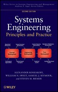
The respective knowledge domains of the systems engineer and the design specialist are shown in Figure 3.1 using the system hierarchy defined above. It shows that the systems engineer’s knowledge needs to extend from the highest level, the system and its environment, down through the middle level of primary system building blocks or components. At the same time, the design specialist’s knowledge needs to extend from the lowest level of parts up through the components level, at which point their two knowledge domains “overlap.” This is the level at which the systems engineer and the design specialist must communicate effectively, identify and discuss technical problems, and negotiate workable solutions that will not jeopardize either the system design process or the capabilities of the system as a whole.

Figure 3.1. Knowledge domains of the systems engineer and the design specialist.
The horizontal boundaries of these domains are deliberately shown as continuity lines in the figure to indicate that they should be extended as necessary to reflect the composition of the particular system. When a subcomponent or part happens to be critical to the system’s operation (e.g., the ill-fated seal in the space shuttle Challenger’s booster rocket), the systems engineer should be prepared to learn enough about its behavior to identify its potential impact on the system as a whole. This is frequently the case in high-performance mechanical and thermomechanical devices, such as turbines and compressors. Conversely, when the specified function of a particular component imposes unusual demands on its design, the design specialist should call on the systems engineer to reexamine the system-level assumptions underlying this particular requirement.
3.3 SYSTEM BUILDING BLOCKS
Using this system model provides systems engineers with a simple method of partitioning a system along a functional and physical dimension: understanding the functional aspects of the system, then partitioning the system into a physical hierarchy. Each dimensional description of the system can then be decomposed into elements. Below is the description of these two categories of building blocks and a recommended set of elements used in defining the components of each.
Functional Building Blocks: Functional Elements
The three basic entities that constitute the media on which systems operate are
- 1. Information: the content of all knowledge and communication,
- 2. Material: the substance of all physical objects, and
- 3. Energy: energizes the operation and movement of all active system components.
Because all system functions involve a purposeful alteration in some characteristic of one or more of these entities, the latter constitutes a natural basis for classifying the principal system functional units. Since information elements are more than twice as populous as the material and energy entities among system functions, it is convenient to subdivide them into two classes: (1) elements dealing with propagating information (e.g., radio signals), to be referred to as signal elements, and (2) those dealing with stationary information (e.g., computer programs), to be referred to as data elements. The former class is primarily associated with sensing and communications and the latter with analysis and decision processes. This results in a total of four classes of system functional elements:
- 1. Signal Elements, which sense and communicate information;
- 2. Data Elements, which interpret, organize, and manipulate information;
- 3. Material Elements, which provide structure and transformation of materials; and
- 4. Energy Elements, which provide energy and motive power.
To provide a context for acquainting the student with significant design knowledge peculiar to each of the four broad classes of functional elements, a set of generic functional elements has been defined that represents the majority of important types for each class.
To make the selected elements self-consistent and representative, three criteria may be used to ensure that each element is neither trivially simple nor inordinately complex and has wide application:
- 1. Significance. Each functional element must perform a distinct and significant function, typically involving several elementary functions.
- 2. Singularity. Each functional element should fall largely within the technical scope of a single engineering discipline.
- 3. Commonality. The function performed by each element can be found in a wide variety of system types.
In configuring the individual functional elements, it is noted that regardless of their primary function and classification, their physical embodiments are necessarily built of material usually controlled by external information and powered by electricity or some other source of energy. Thus, a television set, whose main function is to process information in the form of a radio frequency signal into information in the form of a TV picture and sound, is built of materials, powered by electricity, and controlled by user-generated information inputs. Accordingly, it should be expected that most elements in all classes would have information and energy inputs in addition to their principal processing inputs and outputs.
The above process converges on a set of 23 functional elements, five or six in each class. These are listed in the middle column of Table 3.2. The function of the class as a whole is shown in the left column, and typical applications that might embody the individual elements are listed in the right column. It should be noted that the above classification is not meant to be absolute, but is established solely to provide a systematic and logical framework for discussing the properties of systems at the levels of importance to systems engineers.
TABLE 3.2. System Functional Elements
| Class function | Element function | Applications |
| Signal—generate, transmit, distribute, and receive signals used in passive or active sensing and in communications | Input signal
Transmit signal Transduce signal Receive signal Process signal Output signal | TV camera
FM radio transmitter Radar antenna Radio receiver Image processor |
| Data—analyze, interpret, organize, query, and/or convert data and information into forms desired by the user or other systems | Input data
Process data Control data Control processing Store data Output data Display data | Keyboard
Computer CPU Operating system Word processor Printer |
| Material—provide system structural support or enclosure, or transform the shape, composition, or location of material substances | Support material
Store material React material Form material Join material Control position | Airframe
Shipping container Autoclave Milling machine Welding machine Servo actuator |
| Energy—provide and convert energy or propulsive power to the system | Generate thrust
Generate torque Generate electricity Control temperature Control motion | Turbojet engine
Reciprocating engine Solar cell array Refrigerator Auto transmission |
Fundamentally, the functional design of any system may be defined by conceptually combining and interconnecting the identified functional elements along with perhaps one or two very specialized elements that might perform a unique function in certain system applications so as to logically derive the desired system capabilities from the available system inputs. In effect, the system inputs are transformed and processed through the interconnected functions to provide the desired system outputs.
Physical Building Blocks: Components
System physical building blocks are the physical embodiments of the functional elements consisting of hardware and software. Consequently, they have the same distinguishing characteristics of significance, singularity, and commonality and are at the same level in the system hierarchy, generally one level below a typical subsystem and two levels above a part. They will be referred to as component elements or simply as components.
The classes into which the component building blocks have been categorized are based on the different design disciplines and technologies that they represent. In total, 31 different component types were identified and grouped into six categories, as shown in Table 3.3. The table lists the category, component name, and the functional element(s) with which it is associated. As in the case of functional elements, the component names are indicative of their primary function but, in this case, represent things rather than processes. Many of these represent devices that are in widespread use.
TABLE 3.3. Component Design Elements
| Category | Component | Functional element(s) |
| Electronic | Receiver
Transmitter Data processor Signal processor Communications processors Special electronic equipment | Receive signal
Transmit signal Process data Process signal Process signal/data Various |
| Electro-optical | Optical sensing device
Optical storage device Display device High-energy optics device Optical power generator | Input signal
Store data Output signal/data Form material Generate electricity |
| Electromechanical | Inertial instrument
Electric generator Data storage device Transducer Data input/output device | Input data
Generate electricity Store data Transduce signal Input/output data |
| Mechanical | Framework
Container Material processing machine Material reactor Power transfer device | Support material
Store material Form/join material React material Control motion |
| Thermomechanical | Rotary engine
Jet engine Heating unit Cooling unit Special energy source | Generate torque
Generate thrust Control temperature Control temperature Generate electricity |
| Software | Operating system
Application Support software Firmware | Control system
Control processing Control processing Control system |
The systems engineer’s concern with the implementation of the functional elements within components is related to a different set of factors than those associated with the initial functional design itself. Here, the predominant issues are reliability, form and fit, compatibility with the operational environment, maintainability, producibility, testability, safety, and cost, along with the requirement that product design does not violate the integrity of the functional design. The depth of the systems engineer’s understanding of the design of individual components needs to extend to the place where the system-level significance of these factors may be understood, and any risks, conflicts, and other potential problems addressed.
The required extent and nature of such knowledge varies widely according to the type of system and its constitution. A systems engineer dealing with an information system can expect to concentrate largely on the details of the software and user aspects of the system while considering mainly the external aspects of the hardware components, which are usually standard (always paying special attention to component interfaces). At another extreme, an aerospace system such as an airplane consists of a complex and typically nonstandard assemblage of hardware and software operating in a highly dynamic and often adverse environment. Accordingly, an aerospace systems engineer needs to be knowledgeable about the design of system components to a considerably more detailed level so as to be aware of the potentially critical design features before they create reliability, producibility, or other problems during the product engineering, test, and operational stages.
Common Building Blocks
An important and generally unrecognized observation resulting from an examination of the hierarchical structure of a large variety of systems is the existence of an intermediate level of elements of types that recur in a variety of systems. Devices such as signal receivers, data displays, torque generators, containers, and numerous others perform significant functions used in many systems. Such elements typically constitute product lines of commercial organizations, which may configure them for the open market or customize them to specifications to fit a complex system. In Table 3.1, the above elements are situated at the third or middle level and are referred to by the generic name component.
The existence of a distinctive set of middle-level system building blocks can be seen as a natural result of the conditions discussed in Chapter 1 for the origin of complex systems, namely, (1) advancing technology, (2) competition, and (3) specialization. Technological advances are generally made at basic levels, such as the development of semiconductors, composite materials, light-emitting devices, graphic user interfaces, and so on. The fact of specialization tends to apply such advances primarily to devices that can be designed and manufactured by people and organizations specialized in certain types of products. Competition, which drives technology advances, also favors specialization in a variety of specific product lines. A predictable result is the proliferation of advanced and versatile products that can find a large market (and hence achieve a low cost) in a variety of system applications. The current emphasis in defense system development on adapting commercial off-the-shelf (COTS) components, wherever practicable, attempts to capitalize on economies of scale found in the commercial component market.
Referring back to Table 3.1, it is noted that as one moves up through the hierarchy of system element levels, the functions performed by those in the middle or component level are the first that provide a significant functional capability, as well as being found in a variety of different systems. For this reason, the types of elements identified as components in the figure were identified as basic system building blocks. Effective systems engineering therefore requires a fundamental understanding of both the functional and physical attributes of these ubiquitous system constituents. To provide a framework for gaining an elementary knowledge base of system building blocks, a set of models has been defined to represent commonly occurring system components. This section is devoted to the derivation, classification, interrelationships, and common examples of the defined system building blocks.
Applications of System Building Blocks
The system building block model described above may be useful in several ways:
- 1. The categorization of functional elements into the four classes of signal, data, material, and energy elements can help suggest what kind of actions may be appropriate to achieve required operational outcomes.
- 2. Identifying the classes of functions that need to be performed by the system may help group the appropriate functional elements into subsystems and thus may facilitate functional partitioning and definition.
- 3. Identifying the individual functional building blocks may help define the nature of the interfaces within and between subsystems.
- 4. The interrelation between the functional elements and the corresponding one or more physical implementations can help visualize the physical architecture of the system.
- 5. The commonly occurring examples of the system building blocks may suggest the kinds of technology appropriate to their implementation, including possible alternatives.
- 6. For those specialized in software and unfamiliar with hardware technology, the relatively simple framework of four classes of functional elements and six classes of physical components should provide an easily understood organization of hardware domain knowledge.
3.4 THE SYSTEM ENVIRONMENT
The system environment may be broadly defined as everything outside of the system that interacts with the system. The interactions of the system with its environment form the main substance of system requirements. Accordingly, it is important at the outset of system development to identify and specify in detail all of the ways in which the system and its environment interact. It is the particular responsibility of the systems engineer to understand not only what these interactions are but also their physical basis, to make sure that the system requirements accurately reflect the full range of operating conditions.
System Boundaries
To identify the environment in which a new system operates, it is necessary to identify the system’s boundaries precisely, that is, to define what is inside the system and what is outside. Since we are treating systems engineering in the context of a system development project, the totality of the system will be taken as that of the product to be developed.
Although defining the system boundary seems almost trivial at first glance, in practice, it is very difficult to identify what is part of the system and what is part of the environment. Many systems have failed due to miscalculations and assumptions about what is internal and what is external. Moreover, different organizations tend to define boundaries differently, even with similar systems.
Fortunately, several criteria are available to assist in determining whether an entity should be defined as part of a system:
- Developmental Control. Does the system developer have control over the entity’s development? Can the developer influence the requirements of the entity, or are requirements defined outside of the developer’s sphere of influence? Is funding part of the developer’s budget, or is it controlled by another organization?
- Operational Control. Once fielded, will the entity be under the operational control of the organization that controls the system? Will the tasks and missions performed by the entity be directed by the owner of the system? Will another organization have operational control at times?
- Functional Allocation. In the functional definition of the system, is the systems engineer “allowed” to allocate functions to the entity?
- Unity of Purpose. Is the entity dedicated to the system’s success? Once fielded, can the entity be removed without objection by another entity?
Systems engineers have made mistakes by defining entities as part of the system when, in fact, the span of control (as understood by the above criteria) was indeed small. And typically, either during development or operations, the entity was not available to perform its assigned functions or tasks.
One of the basic choices required early is to determine whether human users or operators of a system are considered part of the system or are external entities. In a majority of cases, the user or operator should be considered external to the system. The system developer and owner rarely have sufficient control over operators to justify their inclusion in the system. When operators are considered external to the system, the systems engineer and the developer will focus on the operator interface, which is critical to complex systems.
From another perspective, most systems cannot operate without the active participation of human operators exercising decision and control functions. In a functional sense, the operators may well be considered to be integral parts of the system. However, to the systems engineer, the operators constitute elements of the system environment and impose interface requirements that the system must be engineered to accommodate. Accordingly, in our definition, the operators will be considered to be external to the system.
As noted earlier, many, if not most, complex systems can be considered as parts of larger systems. An automobile operates on a network of roads and is supported by an infrastructure of service stations. However, these are not changed to suit a new automobile. A spacecraft must be launched from a complex gantry, which performs the fueling and flight preparation functions. The gantry, however, is usually a part of the launch complex and not a part of the spacecraft’s development. In the same manner, the electrical power grid is a standard source of electricity, which a data processing system may utilize. Thus, the supersystems identified in the above examples need not be considered in the engineering process as part of the system being developed but as an essential element in its operational environment, and to the extent required to assure that all interfacing requirements are correctly and adequately defined.
Systems engineers must also become involved in interface decisions affecting designs both of their own and of an interfacing system. In the example of a spacecraft launched from a gantry, some changes to the information handling and perhaps other functions of the gantry may well be required. In such instances, the definition of common interfaces and any associated design issues would need to be worked out with engineers responsible for the launch complex.
System Boundaries: The Context Diagram
An important communications tool available to the systems engineer is the context diagram. This tool effectively displays the external entities and their interactions with the system and instantly allows the reader to identify those external entities. Figure 3.2 shows a generic context diagram. This type of diagram is known as a black box diagram in that the system is represented by a single geographic figure in the center, without any detail. Internal composition or functionality is hidden from the reader. The diagram consists of three components:
- 1. External Entities. These constitute all entities in which the system will interact. Many of these entities can be considered as sources for inputs into the system and destinations of outputs from the system.
- 2. Interactions. These represent the interactions between the external entities and the system and are represented by arrows. Arrowheads represent the direction or flow of a particular interaction. While double-headed arrows are allowed, single-headed arrows communicate clearer information to the reader. Thus, the engineer should be careful when using two-directional interactions—make sure the meanings of your interactions are clear. Regardless, each interaction (arrow) is labeled to identify what is being passed across the interface.

Figure 3.2. Context diagram.
The diagram depicts the common types of interactions that a context diagram typically contains. In an actual context diagram, these interactions would be labeled with the specific interactions, not the notional words used above. The labels need to be sufficiently detailed to communicate meaning, but abstract enough to fit into the diagram. Thus, words such as “data” or “communications” are to be avoided in the actual diagram since they convey little meaning.
- 3.The System. This is the single geographic figure mentioned already. Typically, this is an oval, circle, or rectangle in the middle of the figure with only the name of the system within. No other information should be present.
We can categorize what can be passed across these external interfaces by utilizing our definitions of the four basic elements above. Using these elements and adding one additional element, we can form five categories:
- data,
- signals,
- materials,
- energy, and
- activities.
Thus, a system interacts with its environment (and specifically, the external entities) by accepting and providing either one of the first four elements or by performing an activity that influences the system or the environment in some manner.
Constructing a diagram such as the system context diagram can be invaluable in communicating the boundary of the system. The picture clearly and easily identifies the external interfaces needed and provides a short description of what is being passed into and out of the system—providing a good pictorial of the system’s inputs and outputs.
Figure 3.3 provides a simple example using a typical automobile as the system. Although the system is rather simple, it nicely illustrates all five types of interfaces. Four external entities are identified: users (to include the driver and passengers), the maintainer (which could be a user, but, because of his specialized interactions with the system, is listed separately), an energy source, and the environment. Most systems will interact with these four external entity types. Of course, many other entities may interact with a system as well.

Figure 3.3. Context diagram for an automobile.
The user provides a multitude of inputs to the system, including various commands and controls as well as actions, such as steering and braking. Materials are also passed to the system: cargo. In return, several outputs are passed from the automobile back to the user, including various status indications on the state of the system. Additionally, an activity is performed: entertainment, representing the various forms of entertainment available in today’s automobile. Finally, cargo is returned to the users when desired.
Other entities also interact with the system. The maintainer must provide a request for diagnostics data, typically in the form of signals passed to the auto via an interface. Diagnostics data are returned along with the exchange of parts.
The last two external entities represent somewhat specialized entities: an energy source and the ubiquitous environment. In the automobile case, the energy source provides gasoline to the automobile. This energy source can be one of many types: a gasoline pump at a station or a small container with a simple nozzle. The environment requires some special consideration, if for no other reason than it includes everything not specifically contained in the other external entities. So, in some respects, the environment entity represents “other.” In our example, the automobile will generate heat and exhaust in its typical operation. Additionally, a siren and light from various light bulbs, horns, and signals will also radiate from the auto. The environment is also a source of many inputs, such as physical support, air resistance, and weather.
It takes some thought to identify the inputs, outputs, and activities that are part of the system–environment interaction. The creator of this diagram could have really gone “overboard” and specified temperature, pressure, light, humidity, and a number of other factors in this interaction. This brings up an interesting question: what do we include in listing the interactions between the system and the external entity? For that matter, how do we know whether an external entity should be included in our diagram? Fortunately, there is a simple answer to this: if the interaction is important for the design of the system, then it should be included.
In our automobile case, physical support is important for our design and will influence the type of transmission, steering, and tires. So we include “support” in our diagram. Temperature, humidity, pressure, and so on, will be a factor, but we are not sure about their importance to design, so we group these characteristics under “weather.” This does not mean that the automobile will be designed for all environmental conditions, only that we are not considering all conditions in our design. We should have an idea of the environmental conditions from the requirements, and therefore, we can determine whether they should be in our context diagram.
Output from the system to the environment also depends on whether it will influence the design. The automobile will in fact output many things into the environment: heat, smells, texture, colors … and especially carbon dioxide as part of the exhaust! But which of these influence our design? Four will be major influences: heat, noise from the siren, exhaust, and light. Therefore, we include only those for now and omit the others. We can always go back and update the context diagram (in fact, we should, as we progress through both the systems engineering process and the system development life cycle).
The system context diagram is a very simple yet powerful tool to identify, evaluate, and communicate the boundaries of our system. Therefore, it becomes the first tool we introduce in this book. More will follow that will eventually provide the systems engineer with the collection needed to adequately develop his system.
Types of Environmental Interactions
To understand the nature of the interactions of a system with its surroundings, it is convenient to distinguish between primary and secondary interactions. The former involves elements that interact with the system’s primary functions, that is, represent functional inputs, outputs, and controls; the latter relates to elements that interact with the system in an indirect nonfunctional manner, such as physical supports, ambient temperature, and so on. Thus, the functional interactions of a system with its environment include its inputs and outputs and human control interfaces. Operational maintenance may be considered a quasi-functional interface. Threats to the system are those entities that deny or disrupt the system’s ability to perform its activities. The physical environment includes support systems, system housing, and shipping, handling, and storage. Each of these is briefly described below.
Inputs and Outputs.
The primary purpose of most systems is to operate on external stimuli and/or materials in such a manner as to process these inputs in a useful way. For a passenger aircraft, the materials are the passengers, their luggage, and fuel, and the aircraft’s function is to transport the passengers and their belongings to a distant destination rapidly, safely, and comfortably. Figure 3.4 illustrates some of the large variety of interactions that a complex system has with its operating environment for the case of a passenger aircraft.

Figure 3.4. Environments of a passenger airliner. ILS, instrument landing system.
System Operators.
As noted previously, virtually all systems, including automated systems, do not operate autonomously but are controlled to some degree by human operators in performing their function. For the purposes of defining the systems engineer’s task, the operator is part of the system’s environment. The interface between the operator and the system (human–machine interface) is one of the most critical of all because of the intimate relationship between the control exercised by the operator and the performance of the system. It is also one of the most complex to define and test.
Operational Maintenance.
The requirements for system readiness and operational reliability relate directly to the manner in which it is to be maintained during its operating life. This requires that the system be designed to provide access for monitoring, testing, and repair requirements that are frequently not obvious at the outset, but nevertheless must be addressed early in the development process. Thus, it is necessary to recognize and explicitly provide for the maintenance environment.
Threats.
This class of external entities can be man-made or natural. Clearly, weather could be considered a threat to a system exposed to the elements. For example, when engineering naval systems, the salt water environment becomes a corrosive element that must be taken into consideration. Threats can also be man-made. For example, a major threat to an automatic teller machine (ATM) would be the thief, whose goal might be access to the stored cash. System threats need to be identified early to design countermeasures into the system.
Support Systems.
Support systems are that part of the infrastructure on which the system depends for carrying out its mission. As illustrated in Figure 3.4, the airport, the air traffic control system, and their associated facilities constitute the infrastructure in which an individual aircraft operates, but which is also available to other aircraft. These are parts of the SoS represented by the air transportation system, but for an airplane, they represent standard available resources with which it rousts interface harmoniously.
Two examples of common support systems that have been mentioned previously are the electric power grids, which distribute usable electric power throughout the civilized world, and the network of automobile filling stations and their suppliers. In building a new airplane, automobile, or other systems, it is necessary to provide interfaces that are compatible with and capable of utilizing these support facilities.
System Housing.
Most stationary systems are installed in an operating site, which itself imposes compatibility constraints on the system. In some cases, the installation site provides protection for the system from the elements, such as variations in temperature, humidity, and other external factors. In other cases, such as installations on board ship, these platforms provide the system’s mechanical mounting but, otherwise, may expose the system to the elements, as well as subject it to shock, vibration, and other rigors.
Shipping and Handling Environment.
Many systems require transport from the manufacturing site to the operating site, which imposes special conditions for which the system must be designed. Typical of these are extreme temperatures, humidity, shock, and vibration, which are sometimes more stressful than those characteristic of the operating environment. It may be noted that the impact of the latter categories of environmental interactions is addressed mainly in the engineering development stage.
3.5 INTERFACES AND INTERACTIONS
Interfaces: External and Internal
The previous section described the different ways in which a system interacts with its environment, including other systems. These interactions all occur at various boundaries of the system. Such boundaries are called the system’s external interfaces. Their definition and control are a particular responsibility of the systems engineer because they require knowledge of both the system and its environment. Proper interface control is crucial for successful system operation.
A major theme of systems engineering is accordingly the management of interfaces. This involves
- 1. identification and description of interfaces as part of system concept definition and
- 2. coordination and control of interfaces to maintain system integrity during engineering development, production, and subsequent system enhancements.
Inside the system, the boundaries between individual components constitute the system’s internal interfaces. Here, again, the definition of internal interfaces is the concern of the systems engineer because they fall between the responsibility boundaries of engineers concerned with the individual components. Accordingly, their definition and implementation must often include consideration of design trade-offs that impact on the design of both components.
Interactions
Interactions between two individual elements of the system are effected through the interface connecting the two. Thus, the interface between a car driver’s hands and the steering wheel enables the driver to guide (interact with) the car by transmitting a force that turns the steering wheel and thereby the car’s wheels. The interfaces between the tires of the car and the road both propel and steer the car by transmitting driving traction to the road, and also help cushion the car body from the roughness of the road surface.
The above examples illustrate how functional interactions (guiding or propelling the car) are effected by physical interactions (turning the steering wheel or the drive wheels) that flow across (physical) interfaces. Figure 3.5 illustrates the similar relations between physical interfaces involved in steering an air vehicle and the resulting functional interactions.

Figure 3.5. Functional interactions and physical interfaces.
An important and sometimes less than adequately addressed external system interaction occurs during system maintenance. This activity necessarily requires access to a number of vital system functions for testing purposes. Such access calls for the provision of special test points of the system, which can be sampled externally with a minimum of manipulation. In some complex systems, an extensive set of built-in tests (BITs) is incorporated, which may be exercised while the system is in its operational status. The definition of such interfaces is also the concern of the systems engineer.
Interface Elements
To systematize the identification of external and internal interfaces, it is convenient to distinguish three different types:
- 1. connectors, which facilitate the transmission of electricity, fluid, force, and so on, between components;
- 2. isolators, which inhibit such interactions; and
- 3. converters, which alter the form of the interaction medium. These interfaces are embodied in component parts or subcomponents, which can be thought of as interface elements.
Table 3.4 lists a number of common examples of interface elements of each of the three types, for each of four interaction media: electrical, mechanical, hydraulic, and human. The table brings out several points worthy of note:
- 1. The function of making or breaking a connection between two components (i.e., enabling or disabling an interaction between them) must be considered as an important design feature, often involved in system control.
- 2. The function of connecting nonadjacent system components by cables, pipes, levers, and so on, is often not part of a particular system component. Despite their inactive nature, such conducting elements must be given special attention at the system level to ensure that their interfaces are correctly configured.
- 3. The relative simplicity of interface elements belies their critical role in ensuring system performance and reliability. Experience has shown that a large fraction of system failures occurs at interfaces. Assuring interface compatibility and reliability is a particular responsibility of the systems engineer.
TABLE 3.4. Examples of Interface Elements

3.6 COMPLEXITY IN MODERN SYSTEMS
Earlier in the chapter, we described the system hierarchy—how systems are subdivided into subsystems, then components, subcomponents, and finally, parts (see Table 3.1). And as modern systems grow in complexity, the number, diversity, and complexity of these lower-level subsystems, components, and parts increase. Furthermore, the interactions between these entities also increase in complexity. Systems engineering principles, and their applied practices, are designed to deal with this complexity.
Increasingly, a single system may be, or become, a part of a larger entity. While there are many terms currently in use today to describe this supersystem concept, the term SoS seems to be accepted by a wide variety of organizations. Other terms are found in the literature—some meaning the same thing, some having different connotations.
This section provides a basic introduction to the engineering of entities that are considered “above,” or more complex, than single systems: SoSs and enterprises.
SoS
For our purposes, we will use two definitions to describe what is meant by an SoS. Both come from the U.S. Department of Defense (DoD). The first is the simplest:
A set or arrangement of systems that results when independent and useful systems are integrated into a larger system that delivers unique capabilities
In essence, anytime a set of independently useful systems is integrated together to provide an enhanced capability beyond that of the sum of the individual systems’ capabilities, we have an SoS. Of course, the level of integration could vary significantly. At one end of the spectrum, an SoS could be completely integrated from the earliest development phases, where the individual systems, while able to operate independently, are almost exclusively designed for the SoS. At the other end of the spectrum, multiple systems could be loosely joined for a limited purpose and time span to perform a needed mission, with no more than an agreement of the owners of each system. Thus, a method to capture this range of integration is necessary to fully describe the different nuances of SoSs.
The U.S. DoD produced a systems engineering guide in 2008 specifically for SoS environments and captured this spectrum using four categories. The categories are presented in the order of how tightly coupled the component systems are—from loosely to tightly.
- Virtual. Virtual SoSs lack a central management authority and a centrally agreed-upon purpose for the SoS. Large-scale behavior emerges—and may be desirable—but this type of SoS must rely upon relatively invisible mechanisms to maintain it.
- Collaborative. In collaborative SoSs, the component systems interact more or less voluntarily to fulfill agreed-upon central purposes. Standards are adopted, but there is no central authority to enforce them. The central players collectively decide how to provide or deny service, thereby providing some means of enforcing and maintaining standards.
- Acknowledged. Acknowledged SoSs have recognized objectives, a designated manager, and resources for an SoS; however, the constituent systems retain their independent ownership, objectives, funding, development and sustainment approaches. Changes in the systems are based on collaboration between the SoS and the system.
- Directed. Directed SoSs are those in which the integrated SoS is built and managed to fulfill specific purposes. It is centrally managed during long-term operation to continue to fulfill those purposes as well as any new ones the system owners might wish to address. The component systems maintain an ability to operate independently, but their normal operational mode is subordinated to the central managed purpose.
Although one could argue that the last category, the directed SoS, is closer to a single, complex system than an SoS, the definitions capture the range of situations that exist today when systems are integrated together to perform a function, or exhibit a capability, that is greater than any one system.
As the reader might surmise, engineering and architecting an SoS can be different than engineering and architecting a single system, especially for the two middle categories. System of systems engineering (SoSE) can be different because of the unique attributes of an SoS.
Maier first introduced a formal discussion of SoSs by identifying their characteristics in 1998. Since then, several publications have refined these characteristics; however, they have remained remarkably stable over time. Sage and Cuppan summarized these characteristics:
- 1. Operational Independence of the Individual System. An SoS is composed of systems that are independent and useful in their own right. If an SoS is disassembled into its associated component systems, these component systems are capable of independently performing useful operations independently of one another.
- 2. Managerial Independence of the Individual System. The component systems in an SoS not only can operate independently, but they also generally do operate independently to achieve an intended purpose. Often, they are individually acquired and integrated, and they maintain a continuing operational existence and serve purposes that may be independent of those served by the SoS.
- 3. Geographic Distribution. The geographic dispersion of component systems is often large. Often, these systems can readily exchange only information and knowledge with one another.
- 4. Emergent Behavior. The SoS performs functions and carries out purposes that are not necessarily associated with any component system. These behaviors are emergent properties of the entire SoS and not the behavior of any component system.
- 5. Evolutionary Development. The development of an SoS is generally evolutionary over time. Components of structure, function, and purpose are added, removed, and modified as experience with the system grows and evolves over time. Thus, an SoS is usually never fully formed or complete.
These characteristics have since been refined to include additional characteristics. Although these refinements have not changed the basic characteristics, they did add two important features:
- 6. Self-organization. An SoS will have a dynamic organizational structure that is able to respond to changes in the environment and to changes in goals and objectives for the SoS.
- 7. Adaptation. Similar to a dynamic organization, the very structure of the SoS will be dynamic and respond to external changes and perceptions of the environment.
Engineering an SoS that falls into either the collaborative or acknowledged category must deal with the seven core attributes of SoS. Therefore, the basic tools that we have in systems engineering may not be sufficient. Additional methods, tools, and practices have been developed (and are continuing to be developed) to enable the engineer to develop these complex structures.
Some of these tools come from other branches of mathematics and engineering, such as complexity theory. Attributes such as emergent behavior, self-organization, and adaptation have been examined within this field, and various tools and methods have been developed to represent the inherent uncertainty these attributes bring. The challenge is to keep the mathematics simple enough for application to systems engineering.
Other areas that are being examined to support SoSE include social engineering, human behavior dynamics, and chaotic systems (chaos theory). These areas continue to be appropriate for further research.
Enterprise Systems Engineering
SoSE, by its nature, increases the complexity of developing single systems. However, it does not represent the highest level of complexity. In fact, just as Table 3.1 presented a hierarchy with the system at the apex, we can expand this hierarchy, and go beyond SoSs, to an enterprise. Figure 3.6 depicts this hierarchy.

Figure 3.6. Pyramid of system hierarchy.
Above an SoS lies the enterprise, which typically consists of multiple SoSs within its structure. Furthermore, an enterprise may consist of a varied collection of system types, not all of which are physical. For instance, an enterprise includes human or social systems that must be integrated with physical systems.
Formally, an enterprise is “anything that consists of people, processes, technology, systems, and other resources across organizations and locations interacting with each other and their environment to achieve a common mission or goal.” The level of interaction between these entities varies, just as component systems within an SoS. And many entities fit into this definition. Almost all midsize to large organizations would satisfy this definition. In fact, suborganizations of some large corporations would themselves be defined as an enterprise.
Government agencies and departments would also fit into this definition. And finally, large social and physical structures, such as cities or nations, satisfy the definition.
The source of complexity in enterprise systems engineering is primarily the integration of a diversity of systems and processes. The enterprise typically includes the following components that must be integrated together under the inherent uncertainty of today’s enterprise:
- business strategy and strategic planning,
- business processes,
- enterprise services,
- governance,
- technical processes,
- people management and interactions,
- knowledge management,
- information technology infrastructure and investment,
- facility and equipment management,
- supplies management, and
- data and information management.
Enterprise systems engineering refers to the application of systems engineering principles and practices to engineering systems that are part of an enterprise. Developing the individual component systems of the enterprise is known by this term. Another broader term has also emerged: enterprise engineering. This term, with the “systems” omitted, typically refers to the architecting, development, implementation, and operation of the enterprise as a whole. Some have used the terms interchangeably; however, the two terms refer to different levels of abstraction.
The reason that enterprise systems engineering is deemed more complex than SoSE is that many of the components of an enterprise involve one or more SoSs. Therefore, the enterprise could be considered an integration of multiple SoSs.
Just as new tools and techniques are being developed for SoSE applications, so too are tools, methods, and techniques being developed for this relatively young field.
3.7 SUMMARY
System Building Blocks and Interfaces
The need for a systems engineer to attain a broad knowledge of the several interacting disciplines involved in the development of a complex system raises the question of how deep that understanding needs to be.
Hierarchy of Complex Systems
Complex systems may be represented by a hierarchical structure in that they are composed of subsystems, components, subcomponents, and parts.
The domain of the systems engineer extends down through the component level and extends across several categories. In contrast, the domain of the design specialist extends from the part level up through the component level, but typically within a single technology area or discipline.
System Building Blocks
System building blocks are at the level of components and are the basic building blocks of all engineered systems characterized by both functional and physical attributes. These building blocks are characterized by performing a distinct and significant function and are singular—they are within the scope of a single engineering discipline.
Functional elements are functional equivalents of components and are categorized into four classes by operating medium:
- signal elements, which sense and communicate information;
- data elements, which interpret, organize, and manipulate information;
- material elements, which provide structure and process material; and
- energy elements, which provide energy or power.
Components are the physical embodiment of functional elements, which are categorized into six classes by materials of construction:
- electronic,
- electro-optical,
- electromechanical,
- mechanical,
- thermomechanical, and
- software.
System building block models can be useful in identifying actions capable of achieving operational outcomes, facilitating functional partitioning and definition, identifying subsystem and component interfaces, and visualizing the physical architecture of the system.
The System Environment
The system environment, that is, everything outside the system that interacts with it, includes (1) system operators (part of system function but outside the delivered system); (2) maintenance, housing, and support systems; (3) shipping, storage, and handling; (4) weather and other physical environments; and (5) threats.
Interfaces and Interactions
Interfaces are a critical systems engineering concern, which effect interactions between components and can be classified into three categories: connect, isolate, or convert interactions. They require identification, specification, coordination, and control. Moreover, test interfaces typically are provided for integration and maintenance.
Complexity in Modern Systems
Each system is always part of a larger entity. At times, this larger entity can be classified as a separate system in itself (beyond simply an environment, or “nature”). These situations are referred to as “SoSs.” They tend to exhibit seven distinct characteristics: operational independence of the individual system, managerial independence of the individual system, geographic distribution, emergent behavior, evolutionary development, self-organization, and adaptation.
Enterprise systems engineering is similar in complexity but focuses on an organizational entity. Since an enterprise involves social systems as well as technical systems, the complexity tends to become unpredictable.
PROBLEMS
- 3.1 Referring to Table 3.1, list a similar hierarchy consisting of a typical subsystem, component, subcomponent, and part for (1) a terminal air traffic control system, (2) a personal computer system, (3) an automobile, and (4) an electric power plant. For each system, you need only to name one example at each level.
- 3.2 Give three key activities of a systems engineer that require technical knowledge down to the component level. Under what circumstances should the systems engineer need to probe into the subcomponent level for a particular system component?
- 3.3 Referring to Figure 3.1, describe in terms of levels in the system hierarchy the knowledge domain of a design specialist. In designing or adapting a component for a new system, what typical characteristics of the overall system and of other components must the design specialist understand? Illustrate by an example.
- 3.4 The last column of Table 3.2 lists examples of the applications of the 23 functional elements. List one other example of an application than the one listed for three elements in each of the four classes of elements.
- 3.5 Referring to Figure 3.4, for each of the environments and interfaces illustrated, (1) list the principal interactions between the environment and the aircraft, (2) the nature of each interaction, and (3) describe how each affects the system design.
- 3.6 For a passenger automobile, partition the principal parts into four subsystems and their components. (Do not include auxiliary functions such as environmental or entertainment.) For the subsystems, group together components concerned with each primary function. For defining the components, use the principles of significance (performs an important function), singularity (largely falls within a simple discipline), and commonality (found in a variety of system types). Indicate where you may have doubts. Draw a block diagram relating the subsystems and components to the system and to each other.
- 3.7 In the cases selected in answering Problem 3.5, list the specific component interfaces that are involved in the above interactions.
- 3.8 Draw a context diagram for a standard coffeemaker. Make sure to identify all of the external entities and label all of the interactions.
- 3.9 Draw a context diagram for a standard washing machine. Make sure to identify all of the external entities and label all of the interactions.
- 3.10 In a context diagram, “maintainer” is typically an external entity, providing both activities (i.e., “maintenance”) and materials (e.g., spare parts) to the system, and the system providing diagnostic data back to the maintainer. Describe the nature of the maintainer interfaces and what interactions could be done by the user.
- 3.11 List the test interfaces and BIT indicators in your automobile that are available to the user (do not include those only available to a mechanic).
FURTHER READING
D. Buede. The Engineering Design of Systems: Models and Methods, Second Edition, John Wiley & Sons, 2009.
Department of Defense. Systems Engineering Guide for Systems of Systems. DUSD (A&T) and OSD (AT&L), 2008.
M. Jamshidi, ed. System of Systems Engineering: Innovations for the 21st Century. John Wiley & Sons, 2008.
M. Jamshidi, ed. Systems of Systems Engineering: Principles and Applications. CRC Press, 2008.
M. Maier and E. Rechtin. The Art of Systems Architecting. CRC Press, 2009.
A. Sage and S. Biemer. Processes for system family architecting, design and integration. IEEE Systems Journal, 2007, 1(1), 5–16.
A. Sage and C. Cuppan. On the systems engineering and management of systems of systems and federations of systems. Information Knowledge Systems Management, 2001, 2(4), 325–345.