8
CONCEPT DEFINITION
8.1 SELECTING THE SYSTEM CONCEPT
The concept definition phase of the system life cycle marks the beginning of a serious, dedicated effort to define the functional and physical characteristics of a new system (or major upgrade of an existing system) that is proposed to meet an operational need defined in the preceding conceptual phases. It marks a commitment to characterize the system in sufficient detail to enable its operational performance, time of development, and life cycle cost to be predicted in quantitative terms. As illustrated in Chapter 4 (Figure 4.6), the level of effort in the concept definition phase is sharply greater than in previous phases, as system designers and engineering specialists are added to the systems engineers and analysts who largely staffed the preceding phases. In most needs-driven system developments, this phase is conducted by several competing developers, based on performance requirements developed in the preceding phases by or for the customer. The output of this phase is the selection, from a number of alternative system concepts, of a specific configuration that will constitute the baseline for development and engineering. From this phase on, the system development consists of implementing the selected system concept (with modifications as necessary) in hardware and software, and engineering it for production and operational use.
With the advent and formal definition of systems architecting, this phase has been known in some sources as the system architecture phase. While this may not be entirely appropriate, systems architecting, as it is now defined and understood, is a major activity within this phase. The specifics of systems architecting are discussed in Section 8.8.
Place of the Concept Definition Phase in the System Life Cycle
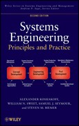
The place of the concept definition phase in the overall system development is shown in Figure 8.1. It constitutes the last phase of the concept development stage and leads to the initiation of the engineering development stage, beginning with the advanced development phase. Its inputs are system performance requirements, the technology base that includes a number of feasible system concepts, and the contractual and organizational framework in which the system development is to be cast. Its outputs are system functional specifications, a defined system concept, and a detailed plan for the ensuing engineering program. The planning outputs of this phase are usually specified to include the systems engineering management plan (SEMP), which defines in detail the systems engineering approach to be followed, the project work breakdown structure (WBS), cost estimates for development and production, test plans, and such other supporting material as may be directed (see Chapter 5).

Figure 8.1. Concept definition phase in system life cycle.
When the customer is the government, laws specify that all acquisition programs be conducted competitively, except in unusual circumstances. The competition frequently occurs during the concept definition phase. It customarily begins with a formal solicitation, which contains the system requirements, usually at the level of total system functionality, performance, and compatibility. Based on this solicitation, competing contractors carry out a proposal preparation effort, which embodies the concept definition phase of the program. The system concept and approach proposed by the successful bidder (or in some cases more than one) then becomes the baseline for the ensuing system development.
In the development of a commercial product, the concept definition phase generally begins after the conclusion of a feasibility study, which established a valid need for the product and the feasibility of meeting this need by one or more technical approaches. It is the point at which the company has decided to commit significant resources to define the product to a degree where a further decision can be made whether or not to proceed to full-scale development. Except for the formality and requirements for detailed documentation, the general technical activities during this phase for commercial and government programs are similar. One or several design concepts may be pursued, depending on the perceived importance of the objective and available funds.
Design Materialization Status
The previous phase was concerned with system design only to the level necessary to define a set of performance requirements that could be realized with a feasible system design, and that would not rule out other advantageous design concepts. For that purpose, it was sufficient to define functions at the subsystem level and only visualize the type of components that would be needed to implement the concept.
In order to define a system to the level where its operational performance, development effort, and production cost can be estimated with any degree of confidence (by analogy with previously developed systems), the conceptual design must be carried one level further. Thus, in the concept definition phase, the design focus is on components, the fundamental building blocks of systems. As indicated in Table 8.1, which is an overlay of Table 4.1, the focus in this phase is on the selection and functional definition of the system components and the definition of their configuration into subsystems.
TABLE 8.1. Status of System Materialization of Concept Definition Phase

Performance of the above tasks is primarily a systems engineering responsibility since they address technical issues that often cut across both technical disciplines and organizational boundaries. However, the functional definition task can be effectively carried out only if the component implementation used to achieve each prescribed function is reasonably well understood and is sufficiently visualized to serve as the basis for risk assessment and costing, which cannot be carried out solely at the functional level. Accordingly, as with many systems engineering tasks, consultation with and advice from experienced design specialists are almost always required, especially in cases where advanced techniques may be used to extend subsystem performance beyond previously achieved levels.
Systems Engineering Method in Concept Definition
The activities in the concept definition phase are discussed in the following sections in terms of the four steps of the systems engineering method (see Chapter 4), followed by a description of the planning of the ensuing system development effort and the formulation of system functional requirements. The four steps, as applied to this phase, are summarized below (generic names in parentheses):
- Performance Requirements Analysis (Requirement Analysis). Typical activities include
- analyzing the system performance requirements and relating them to operational objectives and to the entire life cycle scenario, and
- refining the requirements as necessary to include unstated constraints and quantifying qualitative requirements where possible.
- Functional Analysis and Formulation (Functional Definition). Typical activities include
- allocating subsystem functions to the component level in terms of system functional elements and defining element interactions,
- developing functional architectural products, and
- formulating preliminary functional requirements corresponding to the assigned functions.
- Concept Selection (Physical Definition). Typical activities include
- synthesizing alternative technological approaches and component configurations designed to performance requirements;
- developing physical architectural products; and
- conducting trade-off studies among performance, risk, cost, and schedule to select the preferred system concept, defined in terms of components and architectures.
- Concept Validation (Design Validation). Typical activities include
- conducting system analyses and simulations to confirm that the selected concept meets requirements and is superior to its competitors, and
- refining the concept as may be necessary.
The application of the systems engineering method to the concept definition phase is illustrated in Figure 8.2, which is an elaboration of the generic diagram of Figure 4.12. Inputs are shown to come from the previous (requirements definition) phase in the form of system performance requirements and competitive design concepts. In addition, there are important external inputs in the form of technology, system building blocks (components), tools, models, and an experience knowledge base. Outputs include system functional requirements, a defined system concept, and (not shown in the diagram) detailed plans for the ensuing engineering stage of system development.

Figure 8.2. Concept definition phase flow diagram.
8.2 PERFORMANCE REQUIREMENTS ANALYSIS
As noted in Chapter 4, each phase of development must begin with a detailed analysis of all of the requirements and other terms of reference on which the ensuing program is to be predicated. In terms of problem solving, this is equivalent to first achieving a complete understanding of the problem to be solved.
Analysis of Stated Performance Requirements
Requirements analysis in the concept definition phase is especially important because system performance requirements as initially stated often represent an imperfect interpretation of the user’s actual needs. Even though the previous phases may have been thoroughly carried out, the derivation of a set of performance requirements for a complex system is necessarily an imprecise and often subjective process, not to mention iterative. In particular, the stated requirements tend to be influenced by personal and often not well-founded presumptions of what will turn out to be hard or easy to achieve. This may result in some performance requirements being unnecessarily stringent because they are believed to be readily achievable (a presumption that may turn out to be invalid). It is therefore essential that both the basis for the requirements and their underlying assumptions be clearly understood. Following this, steps can be taken to refine the requirements as necessary to support the definition of a truly viable system concept. The estimated relative difficulty of achieving the requirements will help to guide resource allocation during development.
The task of understanding the source of the given performance requirements in terms of user needs is the particular province of systems engineering. This task requires as intimate an acquaintance with the operational environment and with system users as circumstances may permit. In the case of complex operational systems, such an understanding can best be derived through years of work in the field.
Categories of System Requirements.
In discussing the subject of requirements analysis, attention is usually focused on what functions the system must perform and how well. We have named these types of requirements, functional and performance. Such requirements are generally well defined. There are, however, other types of requirements that may be equally important but may be much more poorly defined, or even omitted up to this point. These include the following:
- 1. Compatibility Requirements: how the system is to interface with its operating site, its logistics support, and with other systems.
- 2. Reliability, Maintainability, Availability (RMA) Requirements: how reliable the system must be to fulfill its purpose, how it will be maintained, and what support facilities will be required.
- 3. Environmental Requirements: what extremes of the physical environment must the system be built to withstand throughout its lifetime.
RMA requirements, when explicitly stated, tend to be arbitrary and often not well defined. For the other two categories, requirements are often largely confined to the system’s operational mode and leave out the conditions of shipping, storage, transit, assembling, and supporting the system. In these circumstances, it is necessary to investigate in detail the entire life of the system, from product delivery to the end of its operating life and its disposition.
System Life Cycle Scenario.
To understand all of the situations that the system will encounter during its lifetime, it is necessary to develop a model or scenario that identifies all of the different circumstances to which the system will be exposed. These will include at least
- 1. storage of the system and/or its components,
- 2. transportation of the system to its operational site,
- 3. assembly and readying the system for operation,
- 4. extended deployment in the field,
- 5. operation of the system,
- 6. routine and emergency maintenance,
- 7. system modification and upgrading, and
- 8. system disposition.
The model of these phases of the system’s use must be sufficiently detailed to reveal any interactions between the system and its environment that will affect its design. For example, the maintenance of the system will require a supply of spare parts, special test equipment, special test points, and other provisions that need to be recognized.
The model also needs to contain information for life cycle costing. Only by visualizing the complete life of the projected system can valid requirements and associated costs be developed.
Completion and Refinement of System Requirements
The development of a system life cycle model will almost always reveal that many important system requirements were not explicitly stated. This is likely to be true not only for the nonoperating phases of the system but also for its interaction with the physical environment. These environmental specifications are often derived from “boiler plate,” especially in many military systems, rather than from a realistic model of the operating environment. In contrast, the desire to make use of standard commercial components may cause such specifications to be unduly relaxed or omitted entirely.
Probably the most important requirement that is often not stated is that of affordability. In competitive system developments, the projected system cost is one of the factors considered in selecting the winning proposal. Therefore, affordability must be considered as equivalent to other stated requirements, even though it may not be represented as such. It is, therefore, necessary to gain as much insight as practicable into what level of projected system cost development, production, and support will constitute an acceptable (or competitive) value.
Useful life is another system characteristic that is seldom stated as a requirement. To prevent early obsolescence, a system that uses high technology must be capable of periodic upgrading or modernization. To make such a process economically viable, the system must be designed with this objective in mind, making those subsystems or components that are susceptible to early obsolescence easy to modify or replace with newer technology.
In some programs, such upgrading or growth capability is explicitly provided for. This process is sometimes called “preplanned product improvement” (P3I). In the majority of cases, however, especially when initial cost is a major concern, there is not a stated requirement for such capability. Nevertheless, it must be kept in mind as an important criterion for comparing alternative system concepts, since in practice, future changes in operating conditions and/or system environment (or product competition) will more often than not lead to increasing pressures for a system upgrade.
Unquantified Requirements.
In order to be useful, a system requirement must be verifiable. This typically means measurable. Where the requirement is stated in nonquantifiable terms, the task of requirements analysis includes endowing it with as much quantification as possible. The following two examples are typical of such requirements.
A commonly unquantified area is that of user requirements, and especially the user–system interface. The overworked term “user friendly” does not translate readily into measurable form. Accordingly, it is important to gain a firsthand understanding of the user’s needs and limitations. This, in turn, is complicated by the fact that there may be several users with different interfacing constraints and levels of training. There is also the maintenance interface, which has totally different requirements.
The interfaces between the system and other equipment at its operating site and with related systems are also often not stated in measurable terms. This may require a firsthand examination of the projected system environment, and even measurements of these interfaces, if necessary. For example, are there specifications for such parameters as available power or input signals that must be provided at the site?
Requirements and the Predecessor System.
As noted previously, if there is a predecessor (current) system that performs the same or similar function as the projected system, as is usually the case, it is the single richest source of information on the requirements for the new system. It deserves detailed study by systems engineering at all stages of development, especially in the formative phases.
The predecessor system offers an excellent basis for understanding the exact nature of the deficiencies that led to the call for a new system. Since all its attributes are measurable, they can serve as a point of departure for quantifying the requirements for the new system. There is frequently documentation available that can provide a direct comparison to requirements for the new system.
The users of the predecessor system are usually the best source of information of what is needed in a new system. Thus, systems engineering should make the effort to gain a detailed firsthand understanding of system operation.
Operational Availability.
There may or may not be a stated requirement for the date at which the system is to be ready for operational use. When there is, it is important to try to understand the priority of meeting this date relative to the importance of development cost, performance, and other system characteristics. This knowledge is needed because these factors are mutually interdependent, and their proper balance is essential to the success of the system development.
In any event, the time of availability is always important to the ultimate value of the system. This is because the growth of technology and competitive pressures operate continuously to shorten the new system’s effective operational life. Thus, the time of operational availability must be considered a prime factor in the planning of a system development. In commercial developments, the first product to exploit a new technology often gains a lion’s share of the market.
Determining Customer/User Needs.
As noted previously, it is always necessary to clarify, extend, and verify the stated system requirements through contacts not only with the customer but also with present users of existing or similar systems.
In a competitive acquisition program, access to the customer may often be formally controlled. However, it should be used, insofar as possible, to clarify ambiguities and inconsistencies in the requirements as originally stated. This may be done directly, through correspondence, or at a bidders’ conference, as appropriate.
A better opportunity to clarify system requirements is in the preproposal stage. In many large acquisition programs, a draft request for proposal (RFP) is circulated to prospective bidders for comment. During this period, it is usually possible to obtain a better understanding of the customer requirements than will be possible after the issuance of the RFP. This emphasizes the fact that the effort to respond to a system acquisition RFP must begin well before (months or years) its formal issuance.
In developing commercial systems, there is always an active and often an extended market survey to establish customer/user needs. In these cases, explicit system requirements may often not yet exist. As a prerequisite to the definition of a system concept and its associated performance requirements, it is therefore essential that systems engineering interact as directly as possible with potential customers and users of current systems to observe at first hand the system strengths, limitations, and associated operating procedures.
8.3 FUNCTIONAL ANALYSIS AND FORMULATION
It has been seen that in keeping with the inherent magnitude of designing a complex system, the systems engineering method divides the design task into two closely coupled steps: (1) analyzing and formulating the functional design of the system (what actions it needs to perform) and (2) selecting the most advantageous implementation of the system functions (how the actions can best be physically generated). The close coupling between these steps results from their mutual interdependence, which requires both visualization of the implementation step in formulating the functional design and iteration of the implementation step when alternative approaches are considered. Those familiar with software engineering will recognize these two steps as design and implementation, respectively.
Definition of Component Functions
The system materialization process in the concept definition phase is mainly concerned with the functional definition of system components (see Table 7.1). If the details of the concept exploration phase are available, the functional configuration at the system level has already been explored (recall the coffeemaker example in Chapter 7). If not, there will have almost always been exploratory studies preceding the formal start of concept definition that have laid out one or more candidate top-level concepts that can serve as a starting point for component functional design.
Functional Building Blocks.
The general nature of the task of translating performance requirements into system functions can be illustrated by using the concept of system functional building blocks as summarized in Chapter 3. Extending the discussion in Chapter 7, the following steps are involved:
- 1. Identification of Functional Media. The type of medium (signals, data, materials, energy, and force) involved in each of the primary system functions can usually be readily associated with one of these five classes, using the criteria suggested in Chapter 7.
- 2. Identification of Functional Elements. Operations on each of the five classes of media are represented by five or six basic functional elements, listed in Chapter 3, each performing a significant function and found in a wide variety of system types. The system actions (functions) can be constructed from a selection of those functional building blocks.
- 3. Relation of Performance Requirements to Element Attributes. Each functional element possesses several key performance attributes (e.g., speed, accuracy, and capacity). If these can be related to the relevant system performance requirement(s), it confirms the correct selection of the functional element.
- 4. Configuration of Functional Elements. The functional elements selected to achieve the required performance characteristics must be interconnected and grouped into integrated subsystems. This may require adding interfacing (input/output) elements to achieve connectivity.
- 5. Analysis and Integration of All External Interactions. The given performance requirements often leave out important interactions of the system with its operational (or other) environment (e.g., external controls or energy source). These interactions need to be integrated into the total functional configuration.
It is not advisable to attempt to optimize at this stage. The initial formulation of the system functional design will need to be modified after the subsequent step of physical definition and the ensuing iteration.
Functional Interactions.
The functional elements are inherently constituted to require a minimum of interconnections to other elements besides primary inputs and outputs. However, most of them depend on external controls and sources of energy, as well as being housed or supported by a material structure. Their grouping into subsystems should be such as to make each subsystem as self-sufficient as possible.
Minimizing critical functional interactions among different subsystems has two purposes. One is to aid the system development, engineering, integration, test, maintenance, and logistics support. The other is to facilitate making future changes in the system during its operational life to upgrade its effectiveness.
When several different ways to group functions (functional configurations) are comparably effective, these alternatives should be carried forward to the next step of the design process where a choice of the superior configuration may be more obvious.
Functional Block Diagramming Tools
Several formal tools and methods exist (and continue to be developed) for representing a system’s functionality and their interactions. Commercial industry has used the functional flow diagram, formally referred to as the functional flow block diagram (FFBD), to represent not only functionality but also the flow of control (or any of the five basic elements). This diagramming technique can be used at multiple levels to form a hierarchy of functionality.
Recently developed is a method known as the integrated definition (IDEF) method. In fact, IDEF extends beyond functionality and now encompasses a range of capability descriptions for a system. Integrated definition zero (IDEF0) is the primary technique for representing system functionality. The basic construct is the functional entity, represented by a rectangle, as shown in Figure 8.3. Strict rules exist for identifying interfaces to and from a function. Sometimes, detail is included within the box, such as the listing of multiple functions performed by the entity; other times, the inside of the rectangle is left blank. Inputs always enter from the left; outputs exit to the right. Controls (separated from inputs) enter the function from the top, and mechanisms (or implementation) enter from the bottom.

Figure 8.3. IDEF0 functional model structure.
One of the simplest diagramming techniques is the functional block diagram (FBD). This technique is similar to FFBDs, but without the flow structure, and IDEF0, but without the diagramming rules. Basically, each function is represented by a rectangle. Interfaces between functions are identified by directional arrows and are labeled to represent what is being passed between the functions. When a function interfaces with an external entity, the entity is represented in some fashion (e.g., rectangle and circle) and an interface arrow is provided.
Recall from Chapter 7 the example of the coffeemaker. Eleven functions were identified; they are relisted here:
Input Functions
- Accept user command (on/off)
- Receive coffee materials
- Distribute electricity
- Distribute weight
Transformative Functions
- Heat water
- Mix hot water with coffee grinds
- Filter out coffee grinds
- Warm brewed coffee
Output Functions
- Provide status
- Facilitate removal of materials
- Dissipate heat
Figure 8.4 represents an FBD using the 11 functions. Three external entities were also identified: the user, a power source (assumed to be an electrical outlet), and the environment. Notice that within the functions list, and the diagram, maintenance is not considered. This is due to the nature of household appliances in general, and coffeemakers in particular. They are not designed to be maintained. They are “expendable” or “throwaway.”

Figure 8.4. Functional block diagram of a standard coffeemaker.
Since it is difficult to avoid crossing lines, several mechanisms exist to distinguish between separate interface arrows. Color is probably the most prevalent. But other methods, such as dashed lines, are used as well. In the case of power, we have simply listed the functions that require power (e.g., “F5”). We have tried to be rather thorough in this example to help the reader think through the process of identifying functions and developing a functional structure for the system. Simplifying this diagram would not be difficult since we could omit several functions at this stage, as long as we did not forget about them later on. For example, function 10, “facilitate removal of materials,” could be omitted at this stage, as long as the ultimate design does indeed allow the user to easily remove materials. Notice as well that we can categorize the functions into those handling the five basic elements:
| Materials | Receive coffee materials |
| Mix hot water with coffee grinds | |
| Filter out coffee grinds | |
| Facilitate removal of materials | |
| Data | Provide status |
| Signals | Accept user commands |
| Energy | Distribute electricity |
| Heat water | |
| Warm brewed coffee | |
| Dissipate heat | |
| Force | Distribute weight |
This is not a “clean” categorization, since some functions input one type of element and convert it into another type. For example, function 2, “accept user commands,” inputs a datum and converts it to signals. Subjective judgment is necessary.
Hardware–Software Allocation.
The issue of whether a given function should be performed by hardware or software may seem like a question of implementation rather than function. However, system-level issues are almost always involved in such decisions, such as the effect on operator interfaces, test equipment, and widespread interaction with other system elements. Accordingly, the definition of functional building blocks makes a clear distinction between software elements (e.g., control system and control processing) and hardware elements (e.g., process signal and process data). For these reasons, the functional definition at the component level should include the allocation of all significant processing functions to either hardware or software. An important consideration in such decisions is provision for future growth potential to keep up with the rapidly advancing data processing technology.
In software-embedded systems, as defined in Chapter 11, software tends to be assigned most of the critical functions, especially those related to controls, because of its versatility. In software-intensive systems, in which virtually all the functionality is performed by software, functional allocation is not as straightforward because of the absence of commonly occurring functional elements. Chapter 11 describes the inherent differences between hardware and software and their effect on system design, and addresses the methods used in designing software system architectures.
To the extent that decisions may be involved in selecting functional elements, configuring them, or quantifying their functional characteristics, trade-offs should be made among the candidates using a set of predefined criteria. The principles and methods of trade-off analysis are described in Chapter 9.
Simulation
The analysis of the behavior of systems that have dynamic modes of response to events occurring in their environment often requires the construction of computer-driven models that simulate such behavior. The analysis of the motion of an aircraft, or for that matter of any vehicle, requires the use of a simulation that embodies its kinematic characteristics.
Simulations can be thought of as a form of experimental testing. They are used to obtain information critical to the design process in a much shorter time and at lesser cost than building and testing system components. In effect, simulations permit designers and analysts to gain an understanding of how a system will behave before the system exists in physical form. Simulations also permit designers to conduct “what-if” experiments by making selected changes in key parameters. Simulations are dynamic; that is, they represent time-dependent behavior. They are driven by a programmed set of inputs or scenarios, whose parameters may be varied to produce the particular responses to be studied, and may include input–output functional models of selected system elements. These characteristics are especially useful for conducting system trade-off studies.
In the concept definition phase, system simulation is particularly useful in the concept selection process, especially in cases where the dynamic behavior of the system is important. Simulation of the several alternative concepts permits the conduct of “experiments” that present the candidates with a range of critical potential challenges. The use of simulation results in scoring the candidates is generally more meaningful and persuasive than using judgment alone. Chapter 9 describes in greater detail some of the different types of simulation used in system development.
Formulation of Functional Specifications
One of the outputs of the concept definition phase is a set of system functional specifications to serve as an input to the advanced development phase. It is appropriate to formulate a preliminary set of functional specifications at this step in the process to lay the groundwork for more formal documents. This also serves as a check on the completeness and consistency of the functional analysis.
In stating functional specifications, it is essential to quantify them insofar as may be inferred from the performance and compatibility requirements. The quantification should be considered provisional at this time, to be iterated during the physical definition step and incorporated into the formal system functional specification document at the end of the concept definition phase. It is at this level in the system hierarchy that the physical configuration becomes clearly evident.
8.4 FUNCTIONAL ALLOCATION
The decisions in the process of concept definition center on the selection of a particular system configuration or concept and the definition of the functions it is to perform. These decisions do more to determine the ultimate performance, cost, and utility of the new system than those in any subsequent phase of the development. Further, in a competitive acquisition process, selection of who will develop the system is largely based on the evaluation of the proposed concept and the supporting documentation. For those reasons, the functional allocation process is of crucial importance.
The systems engineering method calls for such decisions to be made by a structured process that considers the relative merit of a number of alternatives before any one is selected. This process is called “trade-off studies” or “trade-off analysis” and is used in decision-making processes throughout system development. Trade-off analysis is most conspicuously employed during the concept definition phase, largely in the selection of the physical implementation of system components. As stated previously, Chapter 9 contains a description of the principles and methods of trade-off analysis.
Formulation of Alternative Concepts
The first step in selecting a preferred system concept is to formulate a set of alternative solutions, or in this case, system concepts. In the early development phases, the alternative construction begins by allocating the functions identified above to physical components of the system. In other words, we must determine how we will implement the functions above. Of course, this might entail decomposing the top-level functions in an FBD (or other functional representation) into lower-level functions. Many times, this activity provides insight into alternative methods of implementing each function.
As we identify system components, beginning with subsystems, we are constantly faced with the question of whether multiple functions can and should be implemented by a single physical component. The converse is also an issue: should a single function be implemented by multiple subsystems? Ideally, a one-to-one mapping is our goal. However, other factors may lead one to map multiple functions to a single component, or vice versa.
A specific allocation of functions to physical components, and the functional and physical interfaces that result from that allocation, is considered a single alternative. Other allocation schemes will result in different alternatives. The trade-offs mentioned above can occur at multiple levels, from the entire system to individual components. Many times, these trade-offs are part of the functional allocation process.
An important objective is to ensure that no potentially valuable opportunities are omitted. The following paragraphs discuss issues with developing alternatives.
The Predecessor System as a Baseline.
As noted earlier, most system developments are aimed at extending the capabilities or increasing the efficiency of some function that is presently being inadequately performed by an existing system. In cases where the functions of the current system are the same or similar to those of the new system, the current system provides a natural point of departure for system concept definition. Where the main driving force comes from serious deficiencies of limited portions of the current system, an obvious (partial) set of alternative approaches would begin with a minimum modification of the system, restricted to those subsystems or major components that are clearly deficient. Other alternatives would progressively modify or replace other subsystems that may be made obsolescent by modern technology. The general configuration of the system would be retained.
In cases where there are new and improved technological advances at the component level, or when there are standard commercial off-the-shelf components that could be applied to the new system, the impetus for change to a new system would be technology-driven. In this case, a commonly used approach is to introduce improvements sequentially over time as modifications to the current system configuration.
Even when there are reasons against retaining any parts of the current system, as, for example, when moving from a conventional, manually controlled process to an automated and higher-speed operation, the current system’s general functional configuration, component selection, materials of construction, special features, and other characteristics usually provide a useful point of departure for alternative concepts.
Technological Advances.
As noted in Chapter 6, some new system developments are driven more by advances in technology than by operational deficiencies in the previous system. These advances may arise either in exploratory research and development programs aimed at particular application areas, such as development of advanced jet engines, or may come from broadly applicable technology such as high-speed computing and communication devices.
Such advances are often incorporated into an existing system to achieve specific performance improvements. However, if their impact is major, the possibility of a radical departure from the previous configuration should be included among the alternatives. Beyond a certain point, the existing framework may overly constrain the achievable benefits and should therefore be abandoned. Thus, when advanced technology is involved, a wide range of choices for change should be examined.
Original Concepts.
In relatively rare instances, a really different concept is advanced to meet an operational need, especially when the need had not been previously met. In such instances, there is not likely to be a previous system to use for comparison, so that different types of alternatives would need to be examined. Often, various versions of the new concept can be considered, differing in the degree of reliance on new and unproven technology in exchange for projected performance and cost.
Modeling of Alternatives
For comparing alternative concepts, each must be represented by a model that possesses the key attributes on which the relative values of the alternatives will be judged. As a minimum, an FFBD of each should be constructed, and a pictorial or other physical description produced for providing a more realistic view of the system candidate.
Both the above modeling and the simulation of alternative concepts will contribute important context to the selection process and associated trade-offs.
8.5 CONCEPT SELECTION
The objective of trade-off studies in the concept definition phase is to assess the relative “goodness” of alternative system concepts with respect to
- operational performance and compatibility,
- program cost,
- program schedule, and
- risk in achieving each of the above.
The results are judged not only by the degree to which each characteristic is expected to be achieved but also by the balance among them. Such a judgment is of necessity highly program dependent because of the differing priorities that may be placed on the above characteristics.
Design Margins.
In a competitive program, there is always a tendency to maximize system performance so as to gain an edge over competing system proposals. This often results in pushing the system design to a point where various design margins are reduced to a bare minimum. The term “design margin” refers to the amount that a given system parameter can deviate from its nominal value without producing unacceptable behavior of the system as a whole. A reduction in design margins is inevitably reflected in tighter restrictions on the environmentally induced changes in component characteristics during system operation and/or on the fabrication tolerances imposed in the production process. Either can lead to higher program risk, cost, or both. Accordingly, the issue of design margins should be explicitly addressed as an important criterion when selecting a preferred system concept.
System Performance, Cost, and Schedule.
To the extent that stated performance requirements are quantified, are found to be an accurate expression of operational needs, and are within current system capabilities, they may be considered a minimum baseline for the system. However, where they are found to stress the state of the art, or to be desirable rather than truly essential, they need to be considered elastic and capable of being traded off against cost, schedule, risk, or other factors. Unstated requirements found to be significant should always be included among the variables.
Program cost must be derived from the system life cycle cost, which in turn must be derived from a model of the complete system life cycle. The appropriate relative weighting of the near-term versus long-term costs depends on the financial constraints of the acquisition strategy. Specific cost drivers should be identified wherever possible.
The appropriate weighting of schedule requirements is very program dependent and may be difficult to establish. There is an inherent tendency, especially in government and other programs where competition among contractors is especially strong, to estimate both cost and schedule of a new acquisition on the optimistic side, making no provision for the unforeseen delays that always occur in new system developments and are often caused by “unk-unks,” as discussed in Chapter 4. This optimism factor also applies to the estimation of system performance and technical risk. Overall, it tends to slant the trade-off process toward the selection of advanced concepts and optimistic schedules over more conservative ones.
Program Risks.
The assessment of risk is another primary systems engineering task. It involves estimating the probability that a given technical approach will not succeed in achieving the intended objective at an affordable cost. Such risk is present in every previously untried approach. In the development of new complex systems, there are many areas in which risk of failure must be explicitly considered and measures taken to avoid such risks or to reduce their potential impact to manageable levels.
Chapter 5, which devotes a section to the subject of risk management, shows that program risk can be considered to consist of two factors: (1) probability of failure—the probability that the system will fail to achieve an essential program objective, and (2) criticality of failure—the impact of the failure on the success of the program. Thus, the seriousness of each risk can be qualitatively considered as a combination of the probability of the failure weighted by its criticality to the system. For the purposes of this chapter, the following are examples of conditions that may result in a significant probability of program failure:
- A leading-edge unproven technology is to be applied.
- A major increase in performance is required.
- A major decrease in cost is required for the same performance.
- A significantly more severe operating environment is postulated.
- An unduly short development schedule is imposed.
Selection Strategy.
The preceding discussion shows that the principal criteria involved in selecting a preferred system concept are complex, semiquantitative at best, and involve comparisons of incommensurables. This means that the evaluation of the relative merits of alternatives must be such as to expose and illuminate their most critical characteristics and to allow the maximum exercise of judgment throughout the evaluation process.
Two additional guidelines for conducting complex trade-off analyses may be useful: (1) to conserve analytical effort, use a staged approach to the selection process, in which only the most likely winners are subjected to the full system evaluation; and (2) to retain the visibility of the complete evaluation profile of each concept (against each critical measure of effectiveness) until the final selection, rather than combining the components into a single figure of merit, a practice that is often employed but that tends to submerge significant differences.
In pursuing a staged approach, the following suggestions can serve as a checklist, to be applied where appropriate:
- 1. For the first stage of evaluation, make sure that a sufficient number of alternative approaches are considered to address all needs and to explore all relevant technical opportunities.
- 2. If the number of alternatives is larger than can be individually evaluated in detail, perform a preliminary comparison to winnow out the “outliers.” This is equivalent to qualifying the candidates. But be careful not to discard prematurely any candidates that present a new and unique technological opportunity, unless they are inherently incapable of qualifying.
- 3. For the next stage of evaluation, examine the list of performance and compatibility requirements and select a subset of the most critical ones that are also the most likely to reject unsuitable system concepts. Include consideration of growth capability and design margins as appropriate.
- 4. For each candidate concept, evaluate its expected compliance with each selected criterion. In the case of partial noncompliance, attempt to adjust the concept where possible to satisfy the criteria. Estimate the resultant performance, cost, risk, and schedule. In the event of conspicuous imbalance in the above, attempt to modify further the concept to achieve an acceptable balance for all requirements.
- 5. Assign weighting factors or priorities to the evaluation criteria, including cost, risk, and schedule, and apply to the ranking of each concept. Avoid concepts that do not have a sound balance of the above factors.
- 6. For each evaluation criterion, rank order the several candidate concepts.
- 7. Look for and eliminate clear losers.
- 8. Unless there is a single clear winner, perform a significantly more detailed comparison among the two or three potential winners. To this end, develop a life cycle model for each concept, along with a WBS, and a risk abatement plan.
In making the final system concept selection, review the evaluation profile of the merit of each candidate concept against each critical measure of effectiveness to ensure that the choice has no major weaknesses. Check for the sensitivity of the result to a reasonable variation of the weighting of individual criteria.
As stated previously, use each of the above suggestions only where it may be appropriate to the particular selection process. Chapter 9 devotes a section to the fundamentals of trade-off analysis, with an example of their application.
8.6 CONCEPT VALIDATION
The task of designing a model of the system environment to serve as the basis for concept validation builds on the set of parameters initially established for use in the trade-off studies of the selection process.
Modeling the System and Its Environment
Since the degree of system definition at this stage is largely functional, its validation must rely primarily on analysis rather than on testing. The rapid growth of computer modeling and simulation in recent years is providing powerful tools for the validation of complex system concepts.
System Effectiveness Models.
In complex operational systems, system effectiveness models are developed in the needs analysis and concept exploration phases to provide a fuller understanding of the effectiveness of existing systems in performing their missions and in identifying deficiencies that need to be remedied. These are most often computer simulations that include provisions for varying key parameters to establish the sensitivity of overall performance to environmental and system parameter variations and to determine the nature and extent of system changes needed to offset any identified deficiencies (see also Chapter 9).
In the concept definition phase, the construction of system effectiveness models by the system developer depends on whether or not the models used in the previous phases are available, as in the case where the developer is also the customer. In that case, the models can be readily extended to conform to the selected system concept for the validation process. If not, the construction of the model becomes part of the concept definition task. For this and other reasons, the preparation for the competitive effort often begins months (and sometimes years) before the start of the formal competition.
Computer models are also capable of validating a host of subsystem or component-level technical design features. Areas such as aerodynamic design, microwave antennae, hydrodynamics, heat transfer, and many others can be modeled for analysis through the use of special computer codes. Advances in computer capabilities have made such modeling more and more accurate in predicting system behavior for purposes of design and evaluation.
Critical Experiments.
When a proposed system concept relies on technical approaches that have not been previously proven in similar applications, its feasibility must be demonstrated. Often this cannot be done credibly through analysis alone and must be subjected to experimental verification. This is difficult to accommodate in the limited time and constrained resources of a competitive acquisition, but must nevertheless be undertaken to support the proposed system concept.
The term “critical experiment” is appropriate in such instances because it is related to the specific purpose of substantiating a critical feature of the design. It purposely stresses the proposed design feature to its extreme limits to ensure that it is not just marginally satisfactory. The term “experiment” rather than “test” is appropriate because it is performed for the purpose of obtaining sufficient data to understand thoroughly the behavior of the system element, rather than merely to measure whether or not the element operates within certain limits. By the same token, extensive data analyses are also performed to illuminate the system behavior.
Analysis of Validation Results
The analysis of the results of system validation simulations can produce three different types of unsatisfactory findings that require remedial action: (1) deficiencies in the assumed characteristics of the system being modeled, (2) deficiencies in the test model, or (3) excessively stringent system requirements. It is the purpose of the analysis process to attribute the results of the simulation to one or more of the above causes. Beyond these findings, the analysis should also indicate what kind and degree of changes would eliminate the discrepancies. This latter finding usually requires a series of simulations or analyses that test the effect of alternative remedial actions.
The feedback resulting from the validation analysis results in an iterative process in which the system model design and environmental model are refined as necessary to bring the system model in compliance with the requirements.
Iteration of System Concepts and Requirements
The above description of the validation process implies that only one concept was found to be superior in the concept trade-off evaluation, and that this concept was then validated against the full system requirements. Not infrequently, two and sometimes more concepts turn out to be nearly equal in preliminary rankings. In that case, each should be evaluated against the full requirements to see if the more rigorous comparison produces a clear discriminator for selecting the preferred concept.
The system requirements should always be regarded as flexible up to a point. If the validation or trade-off results show that one or more stated requirements appear to be responsible for unduly driving up system complexity, cost, or risk, they should be subjected to critical analysis, and if appropriate, highlighted for discussions with the customer by program management.
8.7 SYSTEM DEVELOPMENT PLANNING
A major product of the concept definition phase is a set of plans that define how the engineering program is to be managed. Among these are the WBS, the life cycle model, the SEMP or its equivalent, system development schedules, the operational (or integrated logistic) support plan, and such others as may be specified by the contracting agency to provide all participants with clear objectives and timescales for accomplishing their respective tasks.
Of the above plans, systems engineering has prime responsibility only for the SEMP. However, it is also deeply involved in all the others by having to provide a detailed description and ongoing assessment of the development process to those who are directly responsible for the other technical management documents. For example, systems engineers are often asked to review initial estimates of the time and effort required to perform a particular engineering task, and based on their appraisal of the associated technical risks, to recommend approval or modification as appropriate.
WBS
The WBS, which was described in Chapter 5, is one of the essential development planning vehicles. The WBS provides a hierarchical framework designed to accommodate all the tasks that need to be accomplished during the entire life of the project. The topmost level represents the project as a whole; the next contains the system product itself, and the principal supporting and management categories. Succeeding levels subdivide the total effort into successively smaller work elements. This subdivision is continued until the complexity and cost of each work element or task are reduced to the point that the task can be directly planned, costed, scheduled, and controlled. The process must ensure that no necessary task is overlooked and that realistic cost and schedule estimates can be made.
The specific form of the WBS is dependent on the nature of the project and is often stipulated in the contract for the system development, especially if the government is the customer. Government programs have had to comply with standards, which define a specific hierarchical structure that provides a logical framework and a place for every aspect of a system product, often with a high degree of detail.
As an example of a typical WBS structure, the system project is at level 1, and the next level (level 2) is broken down into five types of activities, abbreviated from the more detailed descriptions in Chapter 5:
- 1. System Product, including the total effort of developing, producing, and integrating the system itself, together with any auxiliary equipment required for its operation. It includes all of the design, engineering, and fabrication of the system, as well as the testing of its components (unit test).
- 2. System Support (also referred to as “integrated logistics support”), involving provision of equipment, facilities, and services necessary for the development and operation of the system product. It includes all equipment, facilities, and training for both development and system operations.
- 3. System Test, beginning at the integration test level, unit tests of individual components being part of the effort of developing the system product. It includes integration and testing of subsystems and of the total system.
- 4. Project Management, covering the project planning and control effort throughout the program.
- 5. Systems Engineering, covering all aspects of systems engineering support.
The WBS is by its nature an evolving document. As noted previously, it begins in the concept exploration phase, when only the topmost level can be identified. It is in the concept definition phase, when the system components and architecture have been defined, that serious costing and scheduling may be undertaken. Thereafter, the WBS must evolve along with the development and engineering of the system components and progressive discovery and resolution of problems. Thus, at any time, the WBS should reflect the latest knowledge of the program tasks and their status, and should constitute a reliable basis for program planning.
As noted in Chapter 5, the WBS is structured so that every task is identified at the appropriate place within the WBS hierarchy. Systems engineering plays an important role in helping the project manager to structure the WBS so as to achieve this objective.
SEMP
Chapter 5 described the nature and purpose of the planning of the systems engineering tasks that are to be performed in the course of developing a system. In many system acquisition programs, such a plan is referred to as the SEMP and is a required deliverable as part of a proposal for a system development program.
The SEMP is a detailed plan showing how the key systems engineering activities are to be conducted. It typically covers three main activities:
- 1. Development Program Management— including organization, scheduling, and risk management;
- 2. Systems Engineering Process— including requirements, functional analysis, and trade-offs; and
- 3. Engineering Specialty Integration— including reliability, maintainability, producibility, safety, and human factors.
Life Cycle Cost Estimating
The provision of a credible cost estimate for development, production, and (usually) operational support of the proposed new system is a required product of the concept definition phase. While systems engineering is not primarily responsible for this task, it has an essential role in providing key items of information to those who are.
The only basis for deriving costs for a new task is through the identification of a similar and successfully completed task whose costs are known. To this end, the system concept must be decomposed into elements analogous to existing components. Since the concept at this stage is still mainly functional, the systems engineer must visualize the likely physical embodiment of these functions. Once this is done, and any unusual features are identified, those experienced in cost estimating can usually make a reasonable estimate of the prospective costs.
The main guides for deriving system costs are the WBS, the life cycle model, and costing models. The WBS, which spells out all the tasks to be performed during system development, is the chief reference for deriving development costs.
The costs of developing new or modified components are usually derived from estimates provided by those who expect to do the development—whether subcontractors or in-house. Special care must be taken to assure that these estimates reflect an assessment of the associated development risk that is neither unduly optimistic nor overly cautious. These estimates should be reviewed critically by systems engineering to provide a check on the above factors.
The costs for component production, assembly, and testing are usually derived using a cost model developed for this purpose. The cost model is based on the accumulated experience of the developing organization and is updated after each new program. The actual costing is usually done by cost estimating specialists. However, these specialists must rely heavily on the vision of the system elements as provided by systems engineers and the design engineers responsible for component development.
The preparation of cost estimates must not only be as expertly performed as possible, but it must also be documented so as to be credible to management and to the customer. In a competitive acquisition program, the magnitude and credibility of the cost estimates, especially development costs that are the most immediate, weigh heavily in the evaluation.
The “Selling” of the System Development Proposal
The selection of a feasible and affordable concept in the concept definition phase is a necessary but not sufficient step to assure that the engineering of that concept into an operational system will be undertaken. Progression to the engineering development stage requires a management decision to devote much larger resources to the project than have as yet been expended in the conceptual phases. Whether the concept is to be part of a competitive proposal for a formal acquisition program or is to be presented informally to in-house management, there are always other ways to spend the money required to develop the proposed system. Accordingly, such a decision requires compelling evidence that the result will be well worth the cost and time to be expended.
To accomplish its purpose, the concept definition phase must produce persuasive evidence in favor of proceeding with the development of the proposed system. This requires that the reasons for selecting the proposed concept are clear and compelling, that the feasibility of the approach is persuasively demonstrated, and that the plan for carrying out the system development is thoroughly thought out and documented. The end result must be to instill a high degree of confidence that the new system will achieve the required performance within the estimated cost and time and be superior to other potential system approaches.
In developing such a case, it must be remembered that those making the decision to proceed are not likely to be technical experts, so that the evidence will have to be couched in terms that intelligent laymen can understand. This is a very difficult constraint, which must nevertheless be observed. Translating and condensing design specialist jargon and test data into a form that is readily understood, and is clearly relevant to the issues of concept feasibility, risk, and cost, is a very important responsibility that is commonly also assigned to systems engineering.
In this task of selling the system concept and development plan, the following general approach is recommended:
- 1. Show the shortfalls in existing systems and the need to be filled by the proposed system.
- 2. Demonstrate that the proposed concept was selected after a thorough examination of alternatives. Illustrate the alternatives and indicate which main features of the selected system drove the decision.
- 3. Fully discuss program risks and the proposed means for their management. Describe results of critical experiments designed to reveal problems and identify solutions, especially in the application of new technology.
- 4. Display evidence of careful planning of the development and production program. Documents such as the WBS, SEMP, TEMP, and other formal plans give evidence of such planning.
- 5. Present evidence of the organization’s experience and previous successes in system developments of a similar nature, and the carryover of key staff to the proposed system.
- 6. Present the derivation of the life cycle costing for the project and the level of confidence in the conservatism of the estimates.
- 7. Provide further justification as indicated by the specific evaluation criteria listed in the system requirements. Discuss environmental impact analysis if that is an issue.
8.8 SYSTEMS ARCHITECTING
When we think of the word “architecture,” something like Figure 8.5 comes to mind. For many people, architecture refers to buildings, and an architect is someone who designs buildings. Over two decades ago, though, a professor at the University of Southern California challenged that notion. He reasoned that as systems grew in complexity, the top-level design, or more accurately the conceptual design of a system, as defined at the time, was insufficient to guide engineers and designers to accurate and efficient designs. He looked to the field of architecture to understand how complex systems (i.e., buildings) could be created and developed, and (as far as we understand) coined the term “systems architecting.” That man was Eberhardt Rechtin.

Figure 8.5. Traditional view of architecture.
The Institute of Electrical and Electronics Engineers (IEEE) Std 610.12 defines an architecture as “the structure of components, their relationships, and the principles and guidelines governing their design and evolution over time.” This applies to complex systems, such as aircraft, power plants, and spacecraft, as much as buildings. Therefore, Rechtin’s premise was to apply the principles from the field of architecture to systems engineering, not as a replacement, but as part of developing a system.
Dr. Rechtin defined the term systems architecting in this way:
The essence of architecting is structuring. Structuring can mean bringing form to function, bringing order out of chaos, or converting the partially formed ideas of a client into a workable conceptual model. The key techniques are balancing the needs, fitting the interfaces, and compromising among the extremes.
Read closely, the principles of concept development and definition are within his definition. Twenty years ago, conceptual design and components of architecting were lumped into the phrase “preliminary design.” Fortunately, that term has been replaced by the more extensive “architecting.”
Architectural Views
While this section is not intended to present the reader with a full description of systems architecting (see Further Reading for more detail on architecting), we do want to present the basic concepts behind the development of a system architecture. In this vein, most commercial and government work on architectures has followed the notion of architectural views. The idea is this. Develop representations of a system from multiple perspectives, or views, to assist the stakeholders in understanding a system concept (and in making those valuable trade-off decisions) before extensive development has occurred.
While many different architecture development methods and guidelines exist today, all have a very common set of these perspectives. In general, a system architecture will present three common views of a system.
Operational View.
This representation is from the users’ or operators’ perspective. This view would include products that address operational system phases, scenarios, and task flows. Information flow from the users’ perspectives might also be addressed. User interfaces would also be described. Example products that might be included in this view would be operational figures or graphics, scenario descriptions (including use cases), task flow diagrams, organization charts, and information flow diagrams.
Logical View.
This representation is from the manager’s or customer’s perspective. The logical view would include products that define the system’s boundary with its environment and the functional interfaces with external systems, major system functions and behaviors, data flow, internal and external data sets, internal and external users, and internal functional interfaces. Example products for this view would be FFBDs, context diagrams, N2 diagrams, IDEF0 diagrams, data flow diagrams, and various stakeholder-specific products (including business-related products).
Physical View.
This representation is from the designers’ perspective. This view would include products that define the physical system boundary, the system’s physical components and how they interface and interact together, the internal databases and data structures, the information technology (IT) infrastructure of the system and the external IT infrastructure with which the system interfaces, and the standards in force in its development. Example products include physical block diagrams down to a fairly high level of detail, database topologies, interface control documents (ICDs), and standards.
Different architectural guidelines and standards may use different names, but all three of these perspectives are included in every architectural description.
A common question from someone just introduced to the concept of systems architecting is “What is the difference between architecting and designing?” A convenient method of answering that question is to delineate the uses of an architecture versus a design.
A system architecture is used
- to discover and refine operational and functional requirements,
- to drive the system to a specific use or purpose,
- to discriminate between options, and
- to resolve make/buy decisions.
A system design is used
- to develop system components,
- to build and integrate system components, and
- to understand configuration changes as the system is modified.
The nature of these uses means there is a difference between architecting and engineering. Systems architecting is largely an inductive process that focuses on functionality and behavior. Consequently, architecting deals with unmeasurable parameters and characteristics as much if not more than measureable ones. The toolset is largely unquantitative and imprecise—diagramming is a large component of the architect’s toolset. Heuristics typically guide an architect’s decisions rather than algorithms.
Design engineering can be contrasted with architecting since it relies on deductive processes. Engineering focuses on form and physical decomposition and integration. Consequently, design engineering deals with measurable quantities, characteristics, and attributes. Thus, analytical tools derived from physics are the engineer’s primary tools.
Given these characteristics of the two fields (which should certainly not be considered loosely coupled), the architect tends to be active in the early phases of the system development life cycle. The architect tends to be rather dormant during the detailed design, fabrication, and unit testing phases. Integration and system testing will see the architect emerge again to ensure requirements and top-level architectures are being followed. In contrast, the design engineer’s activity peaks during the architect’s dormant phases, though he is by no means completely inactive during the early and late phases of system development.
Architecting in the Engineering Hierarchy.
With the differences between architecting and engineering, it is obvious the two activities are separate. An obvious question then arises: who works for whom? Although there are exceptions, our role of systems architecting leads to the management structure where the architect works for the systems engineer. Systems architecting is a subset of systems engineering. This is different from the role and place of the traditional architect—which is typically at the top. When a new building is designed, developed, and constructed, the architect plays the primary role in the building’s design and continues with that prominent role throughout development and construction. In system development, the systems engineer holds the prominent technical position and the architect works for the systems engineer.
Architecture Frameworks
As mentioned, architectures are used extensively now in large, complex system development programs. The architect and his team have a large latitude in developing and integrating products. This initially led to architectures that were technically accurate but diverse in their structure. In order to standardize the architecture development effort and the products associated with architectures, many organizations developed and mandated the use of architecture frameworks.
An architecture framework is a set of standards that prescribes a structured approach, products, and principles for developing a system architecture. Two early frameworks that emerged were the Command, Control, Communications, Computers, Intelligence, Surveillance and Reconnaissance (C4ISR) Architecture Framework mandated by the U.S. Department of Defense (DoD) and The Open Group Architecture Framework (TOGAF) developed for commercial organizations.
Other frameworks have emerged recently as well, and some that have been around for decades are being recognized as architecture frameworks, though that particular title was not applied until recently (e.g., the Zachman Framework). The early frameworks were focused on individual systems and their architectures. Newer versions, however, have expanded into the field of enterprise architecture, a subset of enterprise engineering or enterprise systems engineering (see Chapter 3 for a discussion of enterprise systems engineering). All of the current versions, including the Department of Defense Architecture Framework (DODAF) and TOGAF, have enterprise editions of their frameworks.
Many architecture frameworks that can be applied to system development exist, even if the primary purpose is enterprise architecting. Below is a selected list of architecture frameworks:
- DODAF
- TOGAF
- The Zachman Framework
- Ministry of Defense Architecture Framework (MODAF)
- Federal Enterprise Architecture Framework (FEAF)
- NATO Architecture Framework (NAF)
- Treasury Enterprise Architecture Framework (TEAF)
- Integrated Architecture Framework (IAF)
- Purdue Enterprise Reference Architecture Framework (PERAF)
DODAF.
Although by no means more important or “better” than any other framework, we discuss the basic products of the DODAF to illustrate the basic components of a framework.
The DOD framework, like all frameworks mentioned, is divided into a series of perspectives, or viewpoints. Figure 8.6 depicts these viewpoints using a figure from the DODAF description. The viewpoints can be observed in three bundles. The first consists of four viewpoints that describe the overall system and its environment: capability, operational, services, and systems. The second bundle consists of the underlying principles, infrastructure, and standards: all data and information and standards. The final bundle is a single viewpoint focusing on the system development project.

Figure 8.6. DODAF version 2.0 viewpoints.
Version 2 of this framework is easily scalable from the system level to the enterprise level, where multiple systems are under development and would be integrated into a legacy system architecture. In fact, each of the three major system-level architecture frameworks, DODAF, MODAF, and TOGAF, are now compatible with enterprise development efforts. Furthermore, with the addition a services viewpoint, service-oriented architectures are now possible within the DODAF framework.
Within each viewpoint, a set of views is defined. A total of 52 views are defined by DODAF, organized within the eight viewpoints. For each view, a variety of methods and techniques are available to represent the view. For example, one view within the operational viewpoint is the operational activity model. This view can be represented by a variety of models, such as the FFBD. Other models can be used to represent the operational activity model, such as an IDEF0 diagram, or a combination of diagrams. Thus, an architecture framework will typically have three layers of entities: a set of viewpoints that compose the framework, a set of views that define each viewpoint, and a set of models that can represent the view.
Every large system development effort must have a minimum set of architecture views. Rarely will a system architecture contain all 52 architecture views. Pertinent views are decided beforehand by the systems engineer and system architect, depending on the intended communication and the appropriate stakeholders.
The key to developing successful system architectures is to understand the purpose of the architecture. Although each system development effort is different, depending on the magnitude and complexity of the system, all architectures have at least one common purpose: to communicate information. Choosing which framework to use, which viewpoints within the framework, which views within the viewpoint, and which models within the view all depends on the purpose the architect is trying to achieve.
The existing frameworks define the superset of viewpoints and views that may be included within the architecture. Within each view, the framework typically suggests candidate models, which can be used to represent the view. A hallmark of the current frameworks, however, is the flexibility inherent within each view. If the architect desires to use a model not included in the candidate list, he can—as long as he does not violate the overall framework constraints.
For example, many of the current frameworks were initially defined using traditional, structured analysis models (e.g., IDEF0, FFBD, data flow diagrams) to define their views. However, engineers familiar with object-oriented (OO) models began to use a combination of OO and structured analysis models to represent views. As the trend increased, the organizations responsible for the common architecture frameworks revised the available models to include OO models that can represent the views. Section 8.9 discusses two languages that implement OO models.
8.9 SYSTEM MODELING LANGUAGES: UNIFIED MODELING LANGUAGE (UML) AND SYSTEMS MODELING LANGUAGE (SysML)
All architecture frameworks use models to represent aspects, perspectives, and views of the system. Traditional models, like standard block diagramming techniques, are based on the top-down decomposition of a system. These methods are typically functionally based and are formed into a hierarchy of models representing attributes of the system in increasing levels of detail. In the 1970s, when software engineering was expanding at a significant rate, a formal modeling construct emerged and was called “structured analysis and design” (SAAD). The term has been applied to systems in general and is not restricted to software systems only.
Models that have been in use for decades resemble many of the SAAD constructs, and they have been grouped into what we call traditional hierarchical methods, or simply traditional systems modeling. This book uses many of the traditional models to represent aspects of systems. This informal modeling language has evolved into an excellent educational language for communicating principles and techniques.
After the advent of SAAD, a new set of modeling languages has emerged, based on object-oriented analysis and design (OOAD) principles. This analysis and design method is primarily bottoms-up in approach and focuses on entities, as opposed to functions, though the two are closely related. In the 1990s, a new modeling language that incorporated OOAD principles and techniques was formalized: the UML.
UML
It was noted that in developing a complex system, it is essential to create high-level models of its structure and behavior to gain an understanding of how it may be configured to meet its requirements. In the development of OOAD methodology, several of the principal practitioners separately developed such models. In the mid-1990s, three of them (Booch, Rumbaugh, and Jacobson), developed a common modeling terminology they called the “UML.” This language has been adopted as a standard by the software community and is widely used throughout industry and government. It is supported by sophisticated tools produced by several major software tool developers.
Whereas structured methodology employs three complementary views of a system, UML provides OO analysts and designers with 13 different ways to diagram different system characteristics. They may be divided into six static or structural diagrams and seven dynamic or behavioral diagrams. Figure 8.7 also lists the two sets of diagrams.

Figure 8.7. UML models.
Structural diagrams represent different views of system entity relationships:
- Class Diagrams show a set of classes, their relationships, and their interfaces.
- Object Diagrams show a set of instances of classes and their relationships.
- Component Diagrams are typically used to illustrate the structure of, and relationships among, physical objects.
- Deployment Diagrams show a static view of the physical components of the system.
- Composite Structure Diagrams provide a runtime decomposition of classes.
- Package Diagrams present a hierarchy of components.
Behavioral diagrams represent different views of system dynamic characteristics.
- Use Case Diagrams show interrelations among a set of use cases representing system functions that respond to interactions with external entities (“actors”).
- Sequence Diagrams show the interactions among a set of objects in executing a system scenario, arranged in chronological order.
- State Machine Diagrams model the transition events and activities that change the state of the system.
- Activity Diagrams are flowcharts of activities within a portion of the system showing control flows between activities.
- Communication Diagrams define links between objects, focusing on their interactions.
- Interaction Overview Diagrams are a mix of sequence and activity diagrams.
- Timing Diagrams present interactions between objects with timing information.
UML class diagrams correspond approximately to entity relationship diagrams in structural analysis, while state chart diagrams correspond to state transition diagrams. Others, especially activity diagrams, are different views of functional flow diagrams.
The new language was quickly adopted by the software engineering community as the de facto standard for representing software concepts and software-intensive systems. Although the origins of the language are in the software world, recently, the language has been used successfully in developing systems that include both hardware and software.
UML is governed by the Object Management Group (OMG), a worldwide consortium. UML will continue to evolve with new releases and added complexity.
Rather than providing examples and explanations to all of the diagrams, we present some examples—several behavioral diagrams: the use case diagram, the activity diagram, and the sequence diagram; and one structural diagram: the class diagram.
Use Case Diagram.
We present the use case diagram first due to its utility in defining a system’s operation. In software, and in some hardware applications, use cases have been used to assist the identification and analysis of operational and functional requirements.
The form of a use case diagram is shown in Figure 8.8, modeling the interaction of an “actor” on the left side (represented by the stick figures) with a single use case (represented by an oval), which leads to a subordinate activity (a separate use case), while the other three interact with a second (external) actor. The arrows indicate the initiation of the use case, not the flow of information. For example, the librarian actor can initiate the “manage loans” use case. The “check-in book” use case may also initiate the same use case.

Figure 8.8. Use case diagram.
Each use case in the diagram represents a separate sequence of activities and events. UML defines a standard set of components for a use case, including
- title;
- short description;
- list of actors;
- initial (or pre-) conditions describing the state of the environment before the use case occurs (or is executed);
- end (or post-) conditions describing the state of the environment after the use case occurs (or has been executed); and
- sequence of events, a list of actions or events that occur in a defined sequence.
Table 8.2 displays an example use case description for “check-out book.” The sequence of events lists the actions and activities that both actors and subsystems execute. In this case, the use case involves one actor and two subsystems—the check-out station and the loan management subsystem. This use case represents an automated check-out system at a library using the Universal Product Code (UPC) symbology.
TABLE 8.2. Use Case Example—“Check-Out Book”

Although not required, it can be beneficial to use columns to separate actions of each actor and subsystem, such as was done in Table 8.2. This allows the reader to easily determine who is performing the action and in what order (sometimes simultaneously). Use cases can, of course, be stylized or tailored to specific situations and may demonstrate the preferences of their authors. In other words, two engineers may come up with different use case sequences of events for the same use case. This may not represent a flaw or problem. In fact, a use case may have several different variants, known in UML as “scenarios.” Unfortunately, the use of the term scenarios differs from our traditional definition provided earlier.
Activity Diagram.
As another example of a behavior diagram, we turn to the activity diagram. Activity diagrams can represent any type of flow inherent in a system, including processes, operations, or control. The diagram accomplishes this through a sequence of activities and events. The sequence of activities and events is regulated via various control nodes. The basic components of the activity diagram are described below:
- Action: an elementary executable step within an activity (rectangle with rounded corners);
- Activity Edge: a connecting link between actions, and between actions and nodes (an arrow); activity edges are further divided into two types: object flows and control flows;
- Object Flow: an activity edge that transports objects (or object tokens);
- Control Flow: an activity edge that represents direction of control (also transports control tokens);
- Pin: a connecting link between action parameters and a flow (a box connected to an action and a flow); a pin accepts explicit inputs or produces explicit outputs from an action;
- Initial Node: the starting point for a control flow (solid circle);
- Final Node: the termination point for a control flow (solid circle within an open circle);
- Decision Node: a branch point for a flow in which each branch flow contains a condition that must be satisfied (diamond);
- Merge Node: a combination point in which multiple flows are merged into a single flow (diamond);
- Fork Node: a point at which a single flow is split into multiple concurrent flows (a solid line segment); and
- Join Node: a point in which multiple flows are synchronized and joined into a single flow (a solid line segment).
Figure 8.9 represents a simple activity diagram, which is analogous to a functional flow diagram, for our library book system. The diagram shows the activity path to split into two concurrent activities, one of which follows one of two logical paths, of returning or borrowing a library book.

Figure 8.9. UML activity diagram.
Sequence Diagram.
Our last behavior diagram is the sequence diagram. These diagrams are usually linked to a use case where actions or events are listed in sequential formats. The sequence diagram takes advantage of this sequence and provides a visual depiction of the sequence of events, tied to the actor or subsystem performing the action.
Figure 8.10 depicts an example sequence diagram of the check-out operation. The diagram is tied to the use case presented above but provides additional information over what was presented in the use case description.

Figure 8.10. UML sequence diagram.
Class Diagram.
At the heart of the UML is the concept of the class and is depicted in the class diagram. A class is simply a set of objects (which can be real or virtual) that have the same characteristics and semantics. In this case, an object can be almost anything and, within the UML, can be represented in software. The class typically describes the structure and behavior of its objects.
Within a class definition, three primary components exist (among others):
- Attributes: the structural properties of the class;
- Operations: the behavior properties of the class; and
- Responsibilities: the obligations of the class.
Classes typically have relationships with other classes. The basic structural relationship is known as an association. Figure 8.11 depicts a simple association between the two classes, “employee” and “company.” The line linking the two classes can have an arrow; however, if no arrow is present, then a bidirectional relationship is assumed. The nature of the association can also be provided by using a triangle. The association is then read like a sentence, “Employee works for company,” and “Company employs employee.” Finally, if the author wants to designate the association as a numerical relationship, he can use multiplicity. Multiplicity designates the numerical aspects of the association and can be expressed with specific numbers or a series of shorthand notations. For example, 0..2 means that any value between 0 and 2 can exist as part of the association. The star symbol, *, is used as a wildcard symbol, and can be thought of as “many.” Thus, in our example, both the star and the number “1” are used to represent the fact that an employee works for only one company, and the company employs many employees.

Figure 8.11. Example of a class association.
Two other relationship types between classes are generalization and dependency. Generalization refers to a taxonomic relationship between a special, or specific, class and a general class. Figure 8.12 depicts a generalization relationship between the three classes, customer, corporate customer, and personal customer. In this case, both the corporate and the personal customers are specific class types belonging to the general class, customer. This relationship is depicted as an arrow with a large arrowhead. In this diagram, the class attributes and operations are provided for each.

Figure 8.12. Example of a class generalization association.
When a generalization relationship is defined, the specific classes inherit the attributes and operations of the parent. Thus, the corporate customer class not only has its own specific attributes and operation but would also contain the attributes Name and Address, in addition to the operation, getCreditRating(). The same is true for the personal customer class.
Dependency is the third type of relationship and denotes the situation where one class requires the other for its specification or implementation. We should note that dependency is a relationship type that can be used among other elements within the UML, not just classes.
Figure 8.13 includes the dependency association with our library example. The class diagram depicts several association types as presents a number of classes that would be defined as part of the library check-out system.

Figure 8.13. Class diagram of the library check-out system.
Systems Modeling Language (SysML)
Although UML has been applied to systems that include both hardware and software, it became evident that a variant form of UML, developed specifically for systems that combine software and hardware, could be used more effectively. Additionally, with the evolution of systems engineering, and specifically systems architecting, during the 1990s, a formal modeling language was recognized as beneficial to establish a consistent standard. The International Council on Systems Engineering (INCOSE) commissioned an effort in 2001 to develop a standard modeling language. Due to its popularity and flexibility, the new language was based on UML, specifically version 2.0. The OMG collaborated with this effort and established the Systems Engineering Domain Special Interest Group in 2001. Together, the two organizations developed and published the systems engineering extension to UML, called the SysML for short.
Perhaps the most important difference between UML and SysML is that a user of SysML need not be an expert in OOAD principles and techniques. SysML supports many traditional systems engineering principles, features, and models. Figure 8.14 presents the diagrams that serve as the basis for the language.

Figure 8.14. SysML models.
A new category, consisting of a single diagram of the same name, has been introduced: the requirements diagram. Only four of the 13 UML diagrams are included without changes: package, use case, state machine, and sequence. Diagrams that rely heavily on OO methodologies and approaches are omitted.
As with UML above, we present an example diagram from each category—in this case three—the requirements diagram, the internal block diagram, and the activity diagram. The latter two correspond closely to the UML class and activity diagrams; however, we will highlight the differences in our discussion.
Requirements Diagram.
In UML, software requirements are primarily captured in the use case descriptions. However, these are primarily functional requirements; nonfunctional requirements are not explicitly presented in UML. Stereotypes were developed in response to this gap; however, SysML introduces a new model that specifically addresses any form of requirements.
Figure 8.15 presents a simple example of a requirements diagram. The primary requirement is the maximum aircraft velocity. This is a system-level requirement that has three attributes: an identification tag, text, and the units of the requirements metric. The text is the “classical” description of the specific requirement. As described in the previous chapters, the system-level requirement has a verification method—in this case a test, indicated by “TestCase.” The details of the AircraftVelocityTest would be found elsewhere.

Figure 8.15. SysML requirements diagram.
This system-level requirement may lead to a set of derived requirements, typically associated with subsystems of the system. In the figure, three derived requirements are included: engine thrust, aircraft weight, and aircraft lift. These requirements would also have attributes and characteristics, although they are not shown in this particular diagram.
Finally, the satisfy relationship is depicted in the figure. This indicates a mechanism, or entity, that will satisfy the derived requirement. In the case of engine thrust, the engine subsystem is responsible for satisfying the derived requirement.
The requirements diagram is typically a series of rectangles that identify and associate many system-level requirements with subsystem-level requirements, their verification methods, derived requirements, and their satisfaction concepts. The latter allows the concept of mapping or tracing requirements to functional and physical entities.
As with operational, performance, and functional requirements, these diagrams are updated throughout the systems engineering method and the system development process. Linkages between components of the requirements model represented in this diagram, and the functional and physical models represented in other SysML diagrams, are crucial to successful systems engineering. Modern tools have been, and are being, developed to facilitate these linkages between model components.
Allocation.
In SysML, a formal mechanism has been developed to enable the user to connect, or bind, elements of different models together. This mechanism is called allocation. SysML provides three types of allocations, although users can define others: behavior, structure, and object flow. The behavior allocation links, or allocates, behavior (represented in one or more of the behavioral diagrams) to a block that realizes this behavior. Recall that behavior is typically an activity or action. The structure allocation links, or allocates, logical structures with physical structures (and vice versa). This mechanism enables the engineer to link components of a logical definition of the system (typically represented by logical blocks) with components of a physical definition of the system (typically represented by physical blocks and packages). Finally, the object flow allocation connects an item flow (found in the structure diagram) with an object flow edge (found in the activity diagram). Allocation can be signified by a dashed arrow in many of the SysML diagrams.
Block Definition Diagram.
In UML, the basic element is the class, with the object representing its instantiation. Because these terms are so closely identified with software development, SysML uses a different name to represent its basic element—the block. The structure and meaning of the block is almost identical to the class. A block contains attributes, may be associated with other blocks, and may also describe a set of activities that it conducts or behaviors it exhibits.
Blocks are used to represent the static structure of a system. They may represent either logical (or functional) elements or physical elements. The latter can also be divided into many types of physical manifestations—hardware, software, documentation, and so on. Figure 8.16 depicts an example block definition. The various components of a block definition are also depicted. This definition would be part of the block definition diagram (or sets of diagrams).

Figure 8.16. SysML block definition.
The block name is at the top. Values are the attributes or characteristics of the radar that are pertinent; the figure displays a sample set of attributes for this radar block. The next section down is the operations or the actions and behaviors of the block. In this example, the radar conducts only two types of operations, DetectTarget and StatusCheck. In reality, of course, common radars would perform many other operations. There may be constraints put on the operations or attributes of the block, so the next section lists any constraints. The block may also be defined with its subsystems or components, typically referred to as “parts.” The example lists six basic subsystems of the radar. Finally, references (to other blocks) are provided.
Figure 8.17 depicts several types of block associations. Associations, similar to their counterparts in UML, represent relationships between blocks. Simple associations are depicted as lines connecting blocks. If direction is needed, then an arrow is placed on one end—this type of association is called a navigable association. Special categories are also available: aggregation associations represent blocks that are part of a whole; composition associations represent blocks that are part of a composite; dependency associations represent blocks that are dependent on other blocks; and generalization associations represent specialized blocks that are incorporated into a general block.

Figure 8.17. SysML block associations.
Activity Diagram.
Of UML’s behavioral diagrams, only one has been significantly expanded within SysML: the activity diagram. Four major extensions have been incorporated:
- Control flow has been extended with control operators.
- Modeling of continuous systems is now enabled using continuous object flows.
- Flows can have associated probabilities.
- Modeling rules for activities have been extended.
With these extensions, some existing functional modeling techniques can be implemented, such as the extended functional flow block diagram (EFFBD). Additionally, with the new extensions, a function tree can be represented quite easily, as shown in Figure 8.18a. This example uses the coffeemaker functions provided in Figure 8.4.


Figure 8.18. (a) SysML functional hierarchy tree. (b) SysML activity diagram.
These functions can be arranged into a more traditional activity diagram, shown in Figure 8.18b. For clarity, the diagram does not include all 11 functions. The general control flow is indicated by the flow arrows and follows the general flow of Figure 8.4 (the FBD). Inputs and outputs are depicted by separate connectors—arrows with pins (or rectangles connected to the activity). These connectors are labeled with the entities passed across the interfaces. A control operator is also included to illustrate this type of special control mechanism. In this case, a control operator regulates what is passed to the Display Status activity, depending on the combination of its three inputs.
We have presented three SysML diagrams to illustrate some of the basic techniques of the language—one from each diagram category. Like UML, SysML offers the systems engineer and the systems architect with a flexible modeling kit with which to represent many aspects and perspectives of a system concept. Furthermore, it overcomes some of the inherent challenges within the UML when representing the more traditional methods of systems engineering, the requirements diagram being perhaps the most relevant example. With the advent of SysML, numerous commercial applications have risen to assist the engineer in developing, analyzing, and refining system concepts.
8.10 MODEL-BASED SYSTEMS ENGINEERING (MBSE)
With the advent of formal modeling languages, such as UML and SysML, and system architecture frameworks, such as DODAF and TOGAF, the ability of systems engineers to represent system requirements, behaviors, and structures has never been greater. Thus, exploring and defining system concepts have now been formalized and a new subset of systems engineering, systems architecting, has risen from obscurity to significance. In broad terms, the system architecture can be thought of as a model of the system, or at least the system concept. This is not to be confused with the fact that the term “model” is also used to denote the basic building blocks of a system architecture.
Soon after the first formal version of UML was released, OMG released the first version of their new model-driven architecture (MDA). This architecture was the first formal architecture framework that recognized the shift from a code-centric software development paradigm to an object-centric paradigm, enabled by the then de facto standard for software engineering model languages, UML. The MDA presented a set of standard principles, concepts, and model definitions that allowed for consistency in defining object models across the software community.
MDA delineated between the real system and its representation by a set of models. These models, in turn, would conform to a metamodel definition, which would in turn, conform to a meta-meta model definition. Several concepts, processes and techniques were presented in the literature using this concept, although the names differed: model-driven development, model-driven system design (MDSD), and model-driven engineering. They were all based on the basic concepts of focusing on a model and its metamodel to represent the system from the early stages of development through deployment and operations.
With the attempt to merge software and systems engineering processes and principles, model-driven development was applied several times to system development in various forms. In 2007, these attempts (along with their techniques and concepts) were grouped by INCOSE under the banner of MBSE. And with the release of the current versions of SysML, this approach has continued to increase in popularity.
The basic notion behind MBSE is that a model of the system is developed early in the process and evolves over the system development life cycle until the model becomes, in essence, the build-to baseline. Early in the life cycle, the models have low levels of fidelity and are used primarily for decision making (not unlike the system architecture in Section 8.8 above). As the system is developed, the level of fidelity increases until the models can be used for design. Finally, the models are transformed yet again into the build-to baseline. At each stage, similar to the standard systems engineering method introduced in Chapter 4, a subprocess is performed to evolve the set of system models. Baker introduced this subprocess for his approach (which he called MDSD). This subprocess is shown in Figure 8.19.

Figure 8.19. Baker’s MDSD subprocesses.
Additionally, Baker defined an early information model, or view, for an MDSD. This is provided in Figure 8.20 and is read similarly to a UML class diagram. The arrows represent the direction of the relationship, not the flow of information.

Figure 8.20. Baker’s information model for MDSD.
Although this approach may sound familiar to the traditional systems engineering approach, several significant differences exist between the two. The foremost difference is the products of each. In traditional systems engineering (including either of the structured analysis or OO approaches), the primary products early in the system development life cycle are documents. Regardless of whether these documents are electronic or paper, they tend to be static representations of the system. With MBSE, the primary products are models, which can be executed to some extent. Thus, reviewing an MDSD (regardless of where one is along the life cycle) involves interrogating a set of models, which is an automated process. Reviewing traditional systems engineering products involves largely reading text and diagrams (although modern representations and displays greatly assist in this).
Of course, there is a price for this ability. Additional computing resources (applications, databases, hardware, visualization, and networking) are required to facilitate the MDSD effort. Currently, few of these resources are available, although more are in development and should be available to engineers soon. Furthermore, until projects are implemented using this approach, we do not yet have a rich lessons learned database.
With this inexperience in mind, INCOSE set about to identify and document the products which implemented this approach in part or whole. The INCOSE MBSE Focus Group published its finding in May 2007 and they identified five methodologies:
- 1. Telelogic’s Harmony®–SE. This proprietary methodology is modeled after the products classical systems engineering “Vee” process, except that a requirements and model repository is established and updated during each step in the process. Additionally, a test data repository is also established and updated to track test cases and data. Several tools and applications have been developed or revised to facilitate the harmony methodology. Telelogic produces several of these (e.g., Rhapsody, Popkin, DOORS), although the methodology itself is application-neutral.
- 2. INCOSE’s Object-Oriented Systems Engineering Method (OOSEM). This approach implements the model-based approach using SysML to support the specification, analysis, design, and verification of a system. The basic set of activities produces artifacts that can be refined and used in other applications. These activities and artifacts are listed below:
- a. Analyze stakeholder needs.
- b. Define system requirements.
- c. Define logical architecture.
- d. Synthesize candidate allocated architectures.
- e. Optimize and evaluate alternatives.
- f. Validate and verify the system.
- 3. IBM’s Rational Unified Process for Systems Engineering (RUP–SE). The goal of the RUP–SE process was to apply the discipline and best practices found in the RUP and to apply them to the challenges of system specification, analysis, design, and development. Moreover, RUP–SE was developed specifically to implement model-driven system development. This adaptation of the existing unified process focuses on four modeling levels: context, analysis, design, and implementation, each incorporating higher levels of fidelity than the previous. These first three model levels are then cross-indexed with six viewpoints: worker, logical, information, distribution, process, and geometric, to produce 17 architecture artifacts (the context/process pair does not produce an artifact, and the implementation model produces actual physical artifacts). These artifacts become the basis of the RUP–SE architecture framework.
- 4. Vitech’s MBSE Methodology. This approach is based on four primary activities that are integrated through a common design repository:
- a. source requirements analysis,
- b. functional/behavior analysis,
- c. architecture/synthesis, and
- d. design validation and verification.
This methodology requires a common information model to manage the syntax and semantics of artifacts. Vitech has defined a system definition language (SDL) for use with their process (which also can be used with their tool, CORE), although the process itself can use any information model language.
- 5. Jet Propulsion Laboratory’s (JPL) State Analysis (SA). This last methodology leverages a model- and state-based control architecture to capture system requirements and design. This process distinguishes between a system’s state and one’s knowledge of that state. Generally, the knowledge of the system state is represented by more abstract concepts than the actual states themselves. How the system evolves from state to state is represented within a set of models. Finally, system control is also represented by models, although complete control is considered impossible due to system complexity.
The establishment and maturation of OO methods, systems modeling languages, and the proliferation of tools and applications implementing those methods and languages have led to an increased awareness of the benefits of using a model-driven approach in systems engineering. And although the approach does come with a price in increased resources, the benefits may indeed provide for an adequate return on investment. Case studies are slowly being offered as “proof” that this approach can indeed work. More time and experience is necessary before the community as a whole embraces MBSE; however, its basic principles are sound. And this methodology and approach is one more step in the convergence of software and systems engineering practices.
8.11 SYSTEM FUNCTIONAL SPECIFICATIONS
The concept definition phase is not complete until a formal basis is created to guide the follow-on engineering design stage. A linchpin of such a basis is a statement describing completely and concisely all the functions that the system must be designed to perform in order to fulfill its operational requirements. In major government acquisitions, such a statement is usually called the “system specification” or “A-Spec.”
The system specification can be thought of as a textual and diagrammatic representation of the system concept. It does not, however, address specifically how the system is implemented to perform its functions but stipulates what functions are to be performed, with what precision, and under what conditions. In so doing, it is essential that the definitions be stated in measurable terms because the engineering implementation of those functions will rely on these definitions.
While the preparation of system specifications is logically a part of the concept definition phase, in a competitive acquisition process, it is usually prepared immediately after the selection process by the successful contractor team. In commercial product development, the process is not as formal but is similar in purpose.
The system specification document should address at least the following subjects:
- System Definition
Mission and concept of operation system functions - Configuration and organization of system interfaces
- Required Characteristics
Performance characteristics (hardware and software) and compatibility requirements - RMA requirements
- Support Requirements
Shipping, handling, and storage training - Special facilities
- Special Requirements
Security and safety human engineering
The leadership and much of the actual work involved in formulating the system specification document is the responsibility of systems engineering.
8.12 SUMMARY
Selecting the System Concept
Objectives of the concept definition phase are to select a preferred system configuration and to define system functional specifications, as well as a development schedule and cost.
Concept definition concludes the concept development stage, which lays the basis for the engineering development stage of the system life cycle. Defining a preferred concept also provides a baseline for development and engineering.
Activities that comprise concept definition are
- Performance Requirements Analysis— relating to operational objectives,
- Functional Analysis and Formulation— allocating functions to components,
- Concept Selection— choosing the preferred concept by trade-off analysis, and
- Concept Validation— confirming the validity and superiority of the chosen concept.
Performance Requirements Analysis
Performance requirements analysis must include ensuring compatibility with the system operating site and its logistics support. The analysis must also address reliability, maintainability, and support facilities, as well as environmental compatibility. A specific focus on the entire life cycle, from production to system disposition, must be kept. Finally, the analysis must resolve the definition of unquantified requirements.
Functional Analysis and Formulation
Functional system building blocks (Chapter 3) are useful for functional definition. The selection of a preferred concept is a systems engineering function, which formulates and compares evaluation of a range of alternative concepts.
Functional Allocation
Developing alternative concepts requires part art and part science. Certainly, the predecessor system can act as a baseline for further concepts (assuming a predecessor is available). Brainstorming and other team innovation techniques can assist in developing alternatives.
Concept Selection
System concepts are evaluated in terms of (1) operational performance and compatibility, (2) program cost and schedule, and (3) risks in achieving each of the above. Program risk can be considered to consist of a combination of two factors: likelihood that the system will fail to achieve its objectives and impact of the failure on the success of the program.
Program risks can result from a number of sources:
- unproven technology,
- difficult performance requirements,
- severe environments,
- inadequate funding or staffing, and
- an unduly short schedule.
Trade-off analysis is fundamental in all systematic decision making.
Concept Validation
In concept selection, trade-off analysis should be
- Organized— set up as a distinct process,
- Exhaustive— consider the full range of alternatives,
- Semiquantitative— use relative weightings of criteria,
- Comprehensive— consider all major characteristics, and
- Documented— describe the results fully.
Justification for the development of the selected concept should
- show the validity of the need to be met;
- state reasons for selecting the concept over the alternatives;
- describe program risks and means for containment;
- give evidence of detailed plans, such as WBS, SEMP, and so on;
- give evidence of previous experience and successes;
- present life cycle costing; and
- cover other relevant issues, such as environmental impact.
System Development Planning
The WBS is essential in a system development program and is organized in a hierarchical structure. It defines all of the constituent tasks in the program.
The SEMP (or equivalent) defines all systems engineering activities through the system life cycle.
Systems Architecting
Systems architecting is primarily the development and articulation of different perspectives, or viewpoints, of a system. Almost all system architectures have at least three perspectives:
- Operational View— a system representation from the user’s or operator’s perspective,
- Logical View— a system representation from the customer’s or manager’s perspective, and
- Physical View— a system representation from the designer’s perspective.
Architecture frameworks define the structure and models used to develop and present a system architecture. These frameworks are meant to ensure consistency across programs in articulating the various perspectives.
System Modeling Languages: UML and SysML
The UML provides 13 system models to represent both structural and behavioral aspects of the system. Although UML was developed for software development applications, it has been successfully applied to software-intensive systems. The language differs from the traditional structured analysis approach by focusing on entities (represented by classes and objects) instead of functions and activities.
The SysML is an extension of UML that enables a more complete modeling of software/hardware systems and facilitates the top-down approach of traditional systems engineering. An emphasis on requirements to drive the development effort is inherent in SysML. To distinguish the two languages, SysML uses the block as its primary entity, in place of the class.
MBSE
The basic notion behind MBSE is that a model of the system is developed early in the process and evolves over the system development life cycle until the model becomes, in essence, the build-to baseline. Early in the life cycle, the models have low levels of fidelity and are used primarily for decision making (not unlike the system architecture in Section 8.8 above). As the system is developed, the level of fidelity increases until the models can be used for design. Finally, the models are transformed yet again into the build-to baseline.
System Functional Specifications
System functional specifications address the system functional description, its required characteristics, and the support requirements.
PROBLEMS
- 8.1 Describe three principal differences between system performance requirements, which are an input to the concept definition phase, and system functional specifications, which are an output (see Fig. 8.1).
- 8.2 Both the concept exploration and concept definition phases analyze several alternative system concepts. Explain the principal differences in the objectives of this process in the two phases and in the manner in which the analysis is performed.
- 8.3 Describe what is meant by the term “functional allocation” and illustrate its application to a personal computer. Draw a functional diagram of a personal computer using the functional elements described in Chapter 3 as building blocks. For each building block, describe what functions it performs, how it interacts with other building blocks, and how it relates to the external inputs and outputs of the computer system.
- 8.4 Under the subsection Program Risks, five examples are listed of conditions that may result in a significant probability of program failure. For each example, explain briefly what consequences of the condition may lead to a program failure.
- 8.5 In the subsection Selection Strategy, it is recommended that in comparing different concepts, the weighted evaluations of the individual criteria for each concept should not be collapsed into a single figure of merit for each concept (as is commonly done) but should be retained in the form of an evaluation “profile.” Explain the rationale for this recommendation and illustrate it with a hypothetical example.
- 8.6 Discuss how you would use trade-off analysis to prioritize the efforts to be allocated to the mitigation of identified high and medium program risks.
- 8.7 The section The “Selling” of the System Development Proposal lists seven elements in a recommended approach to the authorities responsible for making the decision. Illustrate the utility of each element by explaining in each case what the authorities might conclude in the absence of a suitable discussion of the subject.
- 8.8 (a) Develop a top-level function list for an ATM system. Limit yourself to no more than 12 functions.
(b) Draw an FBD of the ATM using the functions in (a). - 8.9 (a) Identify the functions of a common desktop computer.
(b) Identify the components of a common desktop computer.
(c) Allocate the functions in (a) to the components in (b). - 8.10 Suppose you have completed the functional analysis and allocation activities within the concept definition phase of a system’s development.
- (a) Suppose that you have some functions that are allocated to multiple components (as opposed to a single component). What does that mean regarding your conceptual design? Is this a problem?
- (b) Suppose that you have many functions that are allocated to a single component. What does that mean regarding your conceptual design? Is this a problem?
- 8.11 Convert the coffeemaker FBD in Figure 8.4 to an IDEF0 diagram.
- 8.12 Draw a physical block diagram of the coffeemaker represented in Figure 8.4. Within the diagram, use rectangles to represent physical components and label the interfaces between the components.
- 8.13 Draw a diagram that presents the associations and relationships between the following:
- the system,
- system architecture,
- architecture framework,
- viewpoint,
- view,
- modeling language, and
- model.
The diagram should include seven rectangles (one for each entity above) and labeled arrows that describe the relationships between the entities.
- 8.14 Convert the coffeemaker FBD in Figure 8.4 to a UML activity diagram.
- 8.15 Write a two-page essay comparing and contrasting the latest versions of DODAF and TOGAF.
- 8.16 Suppose you are the system architect for a new private business jet aircraft that is intended to seat eight executives. Suppose also that you have been asked to use DODAF as your architecture framework. Decide and explain which views you would include in your architecture. Of course, all of the views within DODAF will not be necessary for this type of system.
- 8.17 Build a matrix that maps UML models to DODAF views. In other words, which UML model(s) would be appropriate for each DODAF view? Hint: many DODAF views will be not applicable while others will have more than a single UML view. Please use a matrix or table.
- 8.18 Repeat Problem 8.17, but map SysML models to DODAF.
- 8.19 Repeat Problem 8.17, but map UML to TOGAF.
- 8.20 Research MBSE and write an essay comparing and contrasting MBSE with traditional systems engineering, as described in Chapters 1–8 of this book. What are the principles of MBSE? What is different? Can traditional systems engineering implement the basic principles without significant upgrades?
FURTHER READING
L. Baker, P. Clemente, B. Cohen, L. Permenter, B. Purves, and P. Salmon. Foundational Concepts for Model Driven System Design. INCOSE Model Driven Design Interest Group, INCOSE, July 2000.
L. Balmelli, D. Brown, M. Cantor, and M. Mott. Model-driven systems development. IBM Systems Journal, 2006, 45(3), 569–585.
B. Blanchard and W. Fabrycky. System Engineering and Analysis, Fourth Edition. Prentice Hall, 2006, Chapter 3.
F. P. Brooks, Jr. The Mythical Man Month—Essays on Software Engineering. Addison-Wesley, 1995.
W. P. Chase. Management of Systems Engineering. John Wiley, 1974, Chapters 3 and 4.
H. Chesnut. Systems Engineering Methods. John Wiley, 1967.
S. Dam. DOD Architecture Framework: A Guide to Applying System Engineering to Develop Integrated, Executable Architectures. SPEC, 2006.
Defense Acquisition University. Systems Engineering Fundamentals. DAU Press, 2001, Chapters 5 and 6.
Defense Acquisition University. Risk Management Guide for DoD Acquisition, Sixth Edition. DAU Press, 2006.
Department of Defense Web site. DoD Architecture Framework Version 2.02. http://cio-nii.defense.gov/sites/dodaf20.
H. Eisner. Computer-Aided Systems Engineering. Prentice Hall, 1988, Chapter 12.
J. A. Estefan. Survey of model-based systems engineering (MBSE) methodologies, INCOSE Technical Document INCOSE-TD-2007-003-02, Revision B, June 10, 2008.
M. Fowler. UML Distilled: A Brief Guide to the Standard Object Modeling Language, Third Edition. Addison-Wesley, 2004.
H. Hoffmann. SysML-based systems engineering using a model-driven development approach. Telelogic White Paper, Version 1, January 2008.
International Council on Systems Engineering. Systems Engineering Handbook. A Guide for System Life Cycle Processes and Activities. Version 3.2, July 2010.
J. Kasser. A Framework for Understanding Systems Engineering. The Right Requirement, 2007.
M. Maier and E. Rechtin. The Art of Systems Architecting. CRC Press, 2009.
The Open Group. TOGAF Version 9 Enterprise Edition, Document Number G091. The Open Group, 2009. http://www.opengroup.org/togaf/.
R. S. Pressman. Software Engineering: A Practitioner’s Approach. McGraw Hill, 2001.
N. B. Reilly. Successful Systems for Engineers and Managers. Van Nostrand Reinhold, 1993, Chapter 12.
A. P. Sage and J. E. Armstrong, Jr. Introduction to Systems Engineering. Wiley, 2000, Chapter 3.
D. Schmidt. Model-driven engineering. IEEE Computer, 2006, 39(2), 25–31.
R. Stevens, P. Brook, K. Jackson, and S. Arnold. Systems Engineering, Coping with Complexity. Prentice Hall, 1998, Chapter 4.