
Chapter 12: Designing the Interim Architecture
We have now reached the point in this book where we will start to look at modernizing the software architecture of our application and refactoring it into microservices. There are a few more services we will be including in our infrastructure architecture to enable this modernization. The remaining chapters will examine implementing the changes we will discuss here. The focus of this chapter is to understand how our infrastructure and software architecture will be changed so that it's ready for the move to microservices. We will look at how utilizing Google Identity Platform and Google Cloud Pub/Sub impacts our infrastructure architecture, as well as how preparing for microservices impacts our software architecture.
In this chapter, we will cover the following topics:
- The infrastructure architecture
- The software architecture
The infrastructure architecture
In this section, we will review our infrastructure architecture as it currently stands, and then look at how we will need to adapt it to add support for Google Identity Platform and Google Cloud Pub/Sub.
Our starting point is the architecture we produced in Chapter 11, Replatforming the Data Layer:

Figure 12.1 – Infrastructure architecture
In this architecture, we have made use of the following resources provided by Google Cloud:
- Relational Database Services using Cloud SQL
- Session-as-a-Service using Cloud Memorystore
- An auto-scaled cluster of Tomcat virtual machines using Regional Managed Instance Groups
- Load balancing using HTTP(s) Load Balancer
- Private networking using Virtual Private Cloud (VPC)
- Network security using Firewall Rules
This architecture has allowed us to reduce the operational overhead by replacing virtual machines with Google Cloud services. These services also addressed our concerns of availability, scalability, and network security.
With this, we have a robust basis for moving forward to start addressing more concerns. The specific concern we will be examining first is identity and authentication. Many traditional applications, such as our example application, handle those concerns themselves. We made use of the security modules provided by Spring Boot to handle identity and authentication. However, that means our application has that responsibility, so making changes to this can be difficult.
Let's examine a scenario. We have had a change request asking that users be given the ability to log in using their Google Identity or Facebook Identity. Normally, we would need to add all the code to handle this to our application.
This is where Identity Platform comes in.
Google Identity Platform
Google Identity Platform provides us with customer identity and authentication as a service. We only need to understand how to use Google Identity Platform rather than every protocol that's used by the various identity providers. This massively simplifies our code base and means that when we need to add a new identity provider, it is a matter of configuration and not development.
The identity providers that are currently supported are as follows:
- OpenID Connect
- SAML
- Microsoft
- Yahoo
- Play games
- GitHub
- Email/password
- Phone
- Anonymous
Important Note
Anonymous is a special identifier that's used for anonymous logins.
This is an impressive list of identity providers that we can use without having to code them. Adding Google Identity Platform to our infrastructure results in the following diagram:

Figure 12.2 – Infrastructure architecture – Identity Platform
We will explore configuring Google Identify Platform and the changes that will be applied to our code base in more detail in Chapter 14, Refactoring the Frontend and exposing REST Services.
The next concern we will address is a consequence of moving to microservices, which we will address with Cloud Pub/Sub.
Cloud Pub/Sub
The microservices will need to communicate with each other, and we want to avoid direct dependencies that could easily result in a fragile architecture where the failure of one microservice could cause many others to fail. To prevent this situation and allow us to easily add behavior to another microservice, we will be applying domain events.
What are domain events? When a microservice has performed its task, it publishes an event to a topic. This event is a record that something has been done. Other microservices that are interested in the event subscribe to the topic and consume that event.
Let's look at an example. In our application, we want to transfer funds between two accounts. This can be accomplished by making a withdrawal from account A and a deposit to account B. However, we are talking about microservices here; is it good practice to have such a service deal with one account at a time? So, we invoke withdrawal on our service for account A and indicate that it is a transfer withdrawal. The details of the withdrawal are recorded in an event, which is then published. The microservice is listening for events and sees the transfer withdrawal. In response, it deposits the same amount to account B. This may seem complex at first glance, but it helps significantly with decoupling microservices, improving the reliability and extensibility of the solution.
Adding Cloud Pub/Sub to our architecture results in the following diagram:

Figure 12.3 – Infrastructure architecture – Cloud Pub/Sub
We will explore using domain events and Cloud Pub/Sub in more detail in Chapter 15, Handling Eventual Consistency with the Compensation Pattern.
With that, we have finished looking at all the major changes we will make to our infrastructure architecture. Additional changes will be examined in Chapter 16, Orchestrating your Application with Google Kubernetes Engine, Chapter 17, Going Serverless with Google App Engine, and Chapter 18, Future-Proofing Your App with Google Cloud Run. Each of those chapters examines one of the options for hosting microservices in a Platform-as-a-Service or serverless environment.
We will now move on to examining the changes we need to make to our software architecture.
The software architecture
Before we start examining how our software architecture needs to change to become cloud native, we need to review the current software architecture.
The following diagram shows how the application is currently structured. This diagram has been simplified, so it does not show repositories or other supporting classes as these don't add much useful information to our refactoring efforts:

Figure 12.4 – Current software architecture (legacy)
To explain the architecture, we will run through how a request is processed. The user of a Web Browser navigates to the application. The URL used invokes an MVC Controller.
The MVC Controller checks if there is an existing session and if so, loads the state from Session as a Service. The MVC Controller then invokes a Domain Service with the information provided from the Web Browser and/or Session.
The Domain Service then retrieves an Aggregate Root from the Relational Database and invokes business logic on that Aggregate Root.
Important Note
Remember that an Aggregate Root is composed of entities and value objects.
If there are any state changes, the Domain Service then updates the Relational Database and returns a result to the MVC Controller.
Finally, the MVC Controller creates a View Bean (which can contain other beans) and hands over control to a Thymeleaf Template.
The Thymeleaf Template then renders an HTML page using the View Bean and returns that page to the Web Browser.
This is highly coupled (tightly bound) and deployed as a single unit in a WAR file. We will be refactoring over time to microservices that are independently buildable, testable, deployable, and scalable components.
However, we will not do this in one go. We will be taking an iterative and incremental approach to this refactoring.
Refactoring the frontend and exposing REST services
The first step in our refactoring process is to separate the user interface and expose the services of the application as REST services.
The following diagram shows that first step. This diagram has been simplified, so it does not show repositories or other supporting classes as these don't add much useful information to our refactoring efforts:

Figure 12.5 – Software architecture – refactored frontend
In this iteration of our software architecture, the user, at a Web Browser, navigates to the application. The URL that's used invokes a static HTML page hosted in Nginx.
The Web Browser renders this page, which contains all the view logic in it, using JavaScript and the AngularJS framework. The Web Browser executes the view logic and invokes the REST service exposed by the REST controller.
The REST controller acts almost exactly as it did in the previous iteration but instead of handing off control to Thymeleaf, it simply returns a Response Bean, which is converted by Spring Boot into a JSON representation of the bean and returned to the Web Browser.
The Web Browser then updates the document object model to populate it with the information returned from the REST service.
Important Note
Nginx acts as a reverse proxy when the URL is exposed by the REST controller. This is how we will initially implement the Strangler Pattern. Nginx will act as a facade for our deployment.
Separating the frontend and backend into two separately deployable units is what allows us to start refactoring the monolith into microservices. It is also the step that allows us to begin using Google Identity Platform.
Adding Google Identity Platform for identity and authentication
As we described earlier, instead of handling identity and authentication in our code base, we will use Google Identity Platform for those tasks.
The following diagram shows how Google Identity Platform fits into our architecture. This diagram has been simplified, so it does not show repositories or other supporting classes as these don't add much useful information to our refactoring efforts:

Figure 12.6 – Software architecture – Google Identity Platform
We will be using the Firebase SDK provided by Google, which simplifies identity and authentication for our user interface. Authentication will occur in the web browser rather than on the server, and we will pass a token from the browser to our REST services to prove we are authenticated and authorized to use the services. The REST controller will communicate with Google Identity Platform to verify that the user has authenticated.
Next, we will look at how our services can publish events and respond to events instead of just being invoked through a REST API.
Publishing events
The first change we will make is to enable publishing events from our application. The following diagram shows how this can be accomplished:
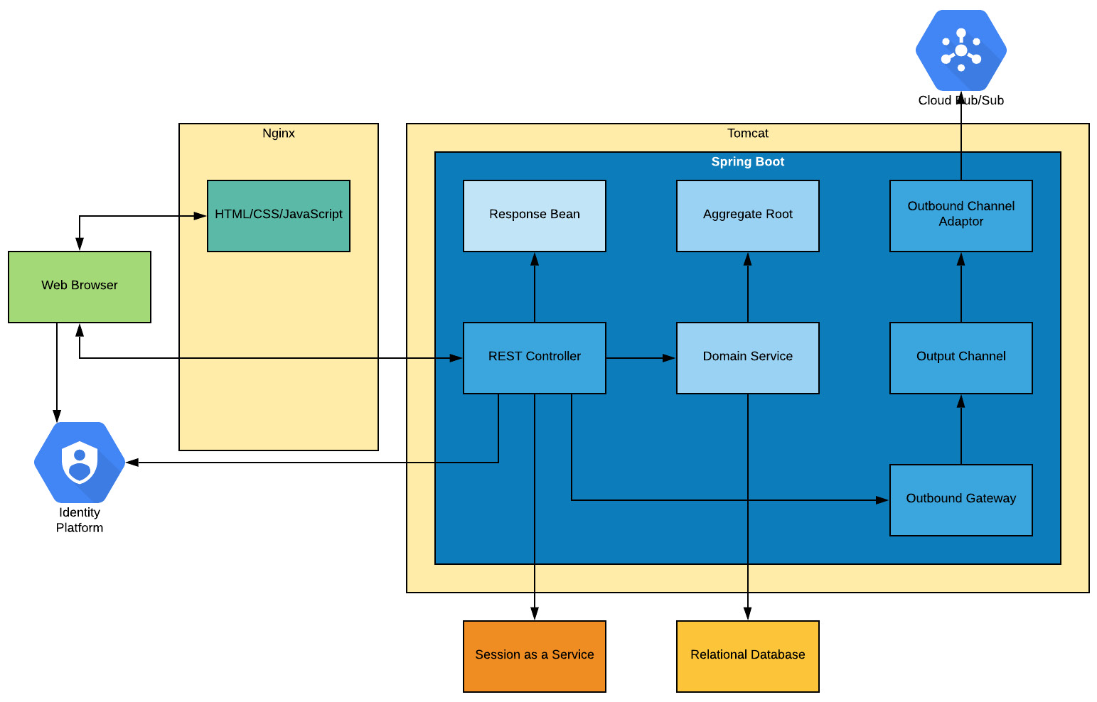
Figure 12.7 – Publishing events
The key elements we have added to our architecture are as follows:
- The Outbound Channel Adaptor: This is what converts between Spring Boot's internal Pub/Sub infrastructure and the Google Cloud Pub/Sub service. Using a different adaptor would allow us to connect to other Pub/Sub services without changing anything else.
- The Outbound Channel: This is the standard Spring Boot support for Pub/Sub.
- The Outbound Gateway: This is the component that places events onto the Outbound Channel.
We have placed the logic to allow outbound events to be published into the REST Controller rather than the Domain Service. This is because the Domain Service methods are transactional, and the Relational Database updates could be rolled back after all our code has been executed. Having this logic in the REST Controller allows us to make sure events are not falsely published, and that failure events can be published correctly.
The next section looks at how to respond to events.
Consuming events
As this section is all about responding to events, we have removed the elements that relate to the frontend from the diagram. Consuming events is not a frontend feature, so these elements would have complicated the following diagram:

Figure 12.8 – Consuming events
In the preceding diagram, we have replaced the REST service with a Service Activator. This receives events from an input channel, which is populated by an inbound channel adaptor. This is the reverse sequence of the previous publishing scenario.
The key elements we have added to our architecture are as follows:
- The Inbound Channel Adaptor: This is what converts between Spring Boot's internal Pub/Sub infrastructure and the Google Pub/Sub service. Using a different adaptor would allow us to connect to other Pub/Sub services without changing anything else.
- The Inbound Channel: This is the standard Spring Boot support for Pub/Sub.
- The Service Activator: This is the component that receives events from the inbound channel and executes whatever logic we have decided on. Usually, we use this to invoke a Domain Service and then publish an event based on the response.
Our final step in refactoring our software architecture is to slice our application into microservices. This is not done in a single step but instead iteratively and incrementally.
Refactoring to microservices
As we mentioned previously, we will be using the Strangler pattern to refactor our application iteratively and incrementally to microservices. Our starting point was a single monolithic application.
The way we apply the Strangler pattern is to separate the frontend from the backend and place a facade between them. Doing so means that we can make changes to the backend without the frontend being aware of those changes. In our initial versions, we will make use of Nginx as a reverse proxy to act as this façade, as well as to host our static content (HTML/CSS/JavaScript). The following diagram illustrates the separation of the frontend and backend and the introduction of the façade:

Figure 12.9 – Strangler facade
With the façade in place, we can start to separate the functionality we want to turn into microservices. As we do so, these microservices will be deployed and the Backend (Monolith) will begin to shrink, as illustrated in the following diagram:

Figure 12.10 – Partially refactored monolith
Eventually, the monolith will have been completely removed, and only the microservices will remain:
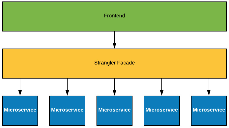
Figure 12.11 – Fully refactored to microservices
Now that we have looked at how we will be applying the Strangler pattern to refactor our application, we need to look at how to decide on the microservice boundaries.
Microservice boundaries
An important question to ask when working with microservices is, how big or small should they be? How can I define what should be a microservice? The approach we will be taking is based on domain-driven design (DDD).
DDD is an approach to software engineering put forward by Eric Evans in his book of the same name. It is often explained as object-orientation done well. When using this approach, there are various building blocks we can use, all of which we have explained previously, and a key one is the Aggregate Root, which is made up of one or more entities (with one being the root) and zero or more value objects.
A key thing here is that the state of all the objects that comprise the Aggregate Root change together in a transaction. They help define the boundaries of a transaction. There are, of course, exceptions but over 95% of the time, a transaction will address a single Aggregate Root instance. We will explain how to handle the remaining 5% in Chapter 15, Handling Eventual Consistency with the Compensation Pattern.
Closely related to our Aggregate Root is another class called a Domain Service. A Domain Service acts on a specific Aggregate Root. As an example, if we have a class called Account as an Aggregate Root, then our Domain Service class would be called AccountService. This service orchestrates retrieving the Aggregate Root from a Repository (the abstraction of a persistent store), invoking the business logic methods of the Aggregate Root, and updating the Repository with the new state of the Aggregate Root.
We have identified what existing classes in our application a microservice would consist of using Aggregate Roots to define the boundary. All that remains is to put a Controller in place. We will follow the same naming conventions that we have for the Account service; this would be the AccountController. This basic structure and boundary of a microservice are illustrated in the following diagram:

Figure 12.12 – Microservice structure
In the preceding diagram, we can see how the classes interact. To summarize, we have the following:
- AccountController: This is the entry point and boundary of our service. The purpose is to separate the different concerns. The controller handles the communication aspects of the service, including how it is invoked.
- AccountService: This is our orchestrator. It interacts with the AccountRepository to obtain and store instances of our AccountAggregate.
- AccountRepository: This is the layer of abstraction that handles communication with the persistent store to create, read, update, and delete information in the database. It is our object-relational mapping.
- AccountAggregate: This represents the thing that our service manages. In this case, this is a bank account.
In this section, we learned how to scope microservices and define boundaries based on DDD. This approach to defining boundaries helps us ensure that the services are not too big that they're monolithic, and not too small that they have excessive interactions.
Summary
In this chapter, we examined our infrastructure architecture and updated it to include Google Identity Platform. This allows us to offload identity and authentication from our code base and make use of an as-a-service offering from Google. We also updated it to include Google Cloud Pub/Sub to support the use of domain events, which we will examine more closely in Chapter 15, Handling Eventual Consistency with the Compensation Pattern.
We then examined our software architecture and looked at how we will refactor the application in the upcoming chapters.
In the next chapter, we will learn how to refactor the frontend and expose the backend with REST services.