Chapter 13. VxLAN BGP EVPN
The following topics are covered in this chapter:
![]() Understanding VxLAN
Understanding VxLAN
![]() Overview of VxLAN BGP EVPN
Overview of VxLAN BGP EVPN
![]() Troubleshooting VxLAN BGP EVPN
Troubleshooting VxLAN BGP EVPN
For years, legacy switching has ruled the data center network. Spanning Tree Protocol (STP) and VLANs have been running in the data center for decades but with the rapidly growing need for virtualization, on-demand virtual machines and increasing customer base, 4K Virtual Local Area Networks (VLAN) (VLAN ID is a 12-bit field) are not sufficient. Also, because of the limitations of STP, such as link/path utilization, convergence issues, Media Access Control (MAC) address table size, and so on, some parts of the network were underutilized. Also, the modern day data centers look for plug-and-play mechanisms for the host virtual machines (VM) and flexibility to move the hosts anywhere in the data center without having to make any changes to the configuration, which is a big challenge with traditional data center designs.
To overcome the growing needs of the data center and the design challenge, Virtual Extensible LAN (VxLAN) is replacing the Spanning Tree Protocol in Layer 2 networks. Thus it becomes important to understand how VxLAN works and how the VxLAN Ethernet VPN (EVPN) solution can help scale VxLAN deployments.
Understanding VxLAN
VxLAN is a MAC-in-unit datagram protocol (UDP) encapsulation method used for extending a Layer 2 or Layer 3 overlay network over an existing Layer 3 infrastructure. The VxLAN encapsulation provides a virtual network identifier (VNI) that can be used to provide segmentation of Layer 2 and Layer 3 data traffic. A VNI is a unique 24-bit segment ID that is used to identify each VxLAN segment. Only hosts within the same VNI are allowed to communicate with each other.
To facilitate the discovery of these VNIs over the underlay Layer 3 network, virtual tunnel end points (VTEP) are used. VTEP is an entity that terminates VxLAN tunnels. It maps Layer 2 frames to a VNI to be used in the overlay network. Encapsulating customer Layer 2 and Layer 3 traffic in VNI over the physical Layer 3 network provides decoupling of overlay from the underlay network and provides flexible overlay topology that is independent of the physical network topology. Each VTEP has two interfaces.
![]() Local LAN segment: Provides a bridging function for local hosts connected to the VTEP. In other words, these are switchport interfaces on the LAN segment to support local endpoint communication through bridging.
Local LAN segment: Provides a bridging function for local hosts connected to the VTEP. In other words, these are switchport interfaces on the LAN segment to support local endpoint communication through bridging.
![]() IP interface: The interface on the core network for VxLAN. The IP address on the IP interface helps in uniquely identifying a VTEP in the network. It is also used for VxLAN encapsulation and deencapsulation.
IP interface: The interface on the core network for VxLAN. The IP address on the IP interface helps in uniquely identifying a VTEP in the network. It is also used for VxLAN encapsulation and deencapsulation.
Figure 13-1 depicts the diagrammatical representation of VTEP. Figure 13-1 shows how end systems (hosts) are connected to the VTEP.

Note
IP intrasubnetwork traffic (bridged) or non-IP Layer 2 traffic is mapped to a VNI that is set aside for the VLAN or bridge domain. Routed traffic, on the other hand, is mapped to a VNI that is set aside for Layer 3 VRF.
Because of the Layer 3 underlay network, VxLANs are capable of performing equal cost multipath (ECMP), link aggregation, and other Layer 3 functionality. Also, because Spanning Tree Protocol is not required anymore, there are no more blocked paths making the network underutilized. VxLANs provides a multi-tenant solution wherein the network traffic is isolated by a tenant and the same VLAN can be used by different tenants.
VxLAN Packet Structure
A VxLAN packet is nothing more than MAC-in-UDP encapsulated packet. The VxLAN header is added to the original Layer 2 frame and then placed in a UDP-IP packet. The VxLAN header is an 8-byte header that consists of 24-bit VxLAN Network Identifier (VNID) and a few reserved bits. The VxLAN header along with the Layer 2 Ethernet frame is then carried as a UDP payload. The VNID uniquely identifies the Layer 2 segments and helps in maintaining isolation among them. Because the VNID is a 24-bit field, VxLAN can support 16 million LAN segments.
Figure 13-2 examines the VxLAN packet format. The two primary fields in the VxLAN header are as follows:
![]() Flags: 8-bits in length, where the fifth bit (I flag) is set to 1 to indicate a valid VNI. The remaining 7 bits (R bits) are reserved fields and are set to zero.
Flags: 8-bits in length, where the fifth bit (I flag) is set to 1 to indicate a valid VNI. The remaining 7 bits (R bits) are reserved fields and are set to zero.
![]() VNI: 24-bit value that provides a unique identifier for the individual VxLAN segment.
VNI: 24-bit value that provides a unique identifier for the individual VxLAN segment.

The other fields shown in the Figure 13-2 are as follows:
![]() Outer UDP Header: The source port in the outer UDP header is dynamically assigned by the originating VTEP. The source port is calculated based on the hash of inner Layer 2/Layer 3/Layer 4 headers of the original frame. The destination port is an Internet Assigned Numbers Authority (IANA) assigned UDP port 4789 or customer configured.
Outer UDP Header: The source port in the outer UDP header is dynamically assigned by the originating VTEP. The source port is calculated based on the hash of inner Layer 2/Layer 3/Layer 4 headers of the original frame. The destination port is an Internet Assigned Numbers Authority (IANA) assigned UDP port 4789 or customer configured.
![]() Outer IP Header: The source IP address in the outer IP header is the originating VTEP’s IP interface. The IP address on the IP interface uniquely identifies a VTEP. The destination address of the outer IP header is the IP address of the destination VTEP’s IP interface.
Outer IP Header: The source IP address in the outer IP header is the originating VTEP’s IP interface. The IP address on the IP interface uniquely identifies a VTEP. The destination address of the outer IP header is the IP address of the destination VTEP’s IP interface.
![]() Outer Ethernet/MAC Header: The source MAC address is the source VTEP MAC address. The destination MAC address is the next-hop MAC address. The next-hop is the interface used to reach the destination or remote VTEP.
Outer Ethernet/MAC Header: The source MAC address is the source VTEP MAC address. The destination MAC address is the next-hop MAC address. The next-hop is the interface used to reach the destination or remote VTEP.
Figure 13-3 depicts the use of a VxLAN overlay between two VTEPs in a data center environment. The data center follows the spine-leaf architecture. The host in VTEP-A tries to communicate with the host in VTEP-B using VxLAN. Host1 and Host2 are VMs; they can also be a physical host, but the forwarding mechanism remains the same.

VxLAN Gateway Types
Frame encapsulation and decapsulation is performed by a VTEP. A VTEP originates and terminates VxLAN tunnels. VxLAN gateway bridges traffic between a VxLAN segment and another physical or logical Layer 2 domain (such as a VLAN). There are two kinds of VxLAN gateways:
![]() Layer 2 Gateway: The Layer 2 gateway is required when the Layer 2 traffic (IEEE 802.1q tagged traffic) comes from VLAN into the VxLAN segment (encapsulation) or the ingress VxLAN packet egresses out an 802.1q tagged interface (decapsulation), where the packet is bridged to a new VLAN.
Layer 2 Gateway: The Layer 2 gateway is required when the Layer 2 traffic (IEEE 802.1q tagged traffic) comes from VLAN into the VxLAN segment (encapsulation) or the ingress VxLAN packet egresses out an 802.1q tagged interface (decapsulation), where the packet is bridged to a new VLAN.
![]() Layer 3 Gateway: A Layer 3 gateway is used when there is a VxLAN to VxLAN routing; that is, when the egress VxLAN packet is routed to a new VxLAN segment. A Layer 3 gateway is also used when there is a VxLAN to VLAN routing; that is, the ingress packet is a VxLAN packet on a routed segment, but the packet egresses out on a tagged 802.1q interface and the packet is routed to a new VLAN.
Layer 3 Gateway: A Layer 3 gateway is used when there is a VxLAN to VxLAN routing; that is, when the egress VxLAN packet is routed to a new VxLAN segment. A Layer 3 gateway is also used when there is a VxLAN to VLAN routing; that is, the ingress packet is a VxLAN packet on a routed segment, but the packet egresses out on a tagged 802.1q interface and the packet is routed to a new VLAN.
VxLAN Overlay
The VxLAN overlay mechanism requires that the VTEPs peer with each other so that the data can be forwarded to the relevant destination. There are primarily three mechanisms for establishing VxLAN overlay:
![]() Flood and learn
Flood and learn
![]() Ingress replication
Ingress replication
![]() BGP EVPN
BGP EVPN
VxLAN Flood-and-Learn Mechanism
VxLAN RFC 7348 defines a multicast-based flood-and-learn mechanism for VxLAN overlay establishment. The flood-and-learn mechanism is a data plane learning technique for VxLAN, where a VNI is mapped to a multicast group on a VTEP. The underlay requires standard routing for VTEP connectivity and must be enabled for multicast. Because there is no control or signaling protocol defined, emulation of multidestination traffic is handled through the VxLAN IP underlay through the use of segment control multicast groups.
The host traffic is usually in broadcast, unknown unicast, or multicast (BUM) format. The BUM traffic is flooded to the multicast delivery group for the VNI that is sourcing the host packet. The remote VTEPs that are part of the multicast group learn the remote host MAC, VNI, and source VTEP IP information from the flooded traffic (just like Address Resolution Protocol (ARP) in traditional switched networks). Unicast packets to the host MAC are sent directly to the destination VTEP as a VxLAN packet.
Figure 13-4 demonstrates the VxLAN overlay flood-and-learn mechanism packet flow with the help of an example. Host-A is connected to VTEP-1 with IP 192.168.1.1 and MAC address MAC-A; Host-B is connected to VTEP-2 with IP 192.168.2.2 and MAC address as MAC-B; and VTEP-3 has IP address 192.168.3.3 and MAC address as MAC-C. In this example, Host-A is having MAC address as MAC-A and IP address as IP A. Similarly, Host-B has a MAC address as MAC-B and IP address as IP B. In this example the core multicast group is 239.1.1.1.

The following steps describe the complete packet flow as shown in Figure 13-4.
Step 1. The End System A with MAC-A and IP A sends an ARP request for host with IP B. The source MAC address of the ARP packet is MAC-A and the destination MAC address is FFFF.FFFF.FFFF. Suppose the host is in VLAN 10. This packet is sent toward VTEP-1. VTEP-1 has VNID 10 mapped to VLAN 10.
Step 2. When the ARP request is received on VTEP-1, the packet is encapsulated and forwarded to the remote VTEP-2 and VTEP-3 with the source as 192.168.1.1 and the destination as 239.1.1.1 as a VxLAN packet. When the encapsulation is done, the VNID is set to 10, the source MAC of the packet is MAC-1, and the destination MAC is 0001.5E01.0101, which is the multicast MAC address for 239.1.1.1.
Step 3. Both the VTEP-2 and VTEP-3 receive the VxLAN packet and deencapsulate it to forward it to the End Systems connected to the respective VTEPs. Note that at this point, both VTEP-2 and VTEP-3 update their MAC address table with the following information:
![]() MAC Address—MAC-A
MAC Address—MAC-A
![]() VxLAN ID—10
VxLAN ID—10
![]() Remote VTEP—192.168.1.1
Remote VTEP—192.168.1.1
In other words, both VTEP-2 and VTEP-3 now know that the MAC address MAC-A is behind VTEP-A and is learned over VNID 10.
Step 4. After the ARP packet is forwarded to Host-B after deencapsulation, Host-B responds back with the ARP reply.
Step 5. When the ARP reply reaches VTEP-2, VTEP-2 already knows that to reach MAC-A, it needs to go to VTEP-1. Thus, VTEP-2 forwards the ARP reply from Host-B as a unicast VxLAN packet.
Step 6. When the VxLAN packet reaches VTEP-1, it then updates its MAC address table with the following information:
![]() MAC Address—MAC-B
MAC Address—MAC-B
![]() VxLAN ID—10
VxLAN ID—10
![]() Remote VTEP—192.168.2.2
Remote VTEP—192.168.2.2
Step 7. After the MAC table is updated on VTEP-1, the ARP reply is forwarded to Host-A.
Note
In Step 2, only those VTEPs that have subscribed to that multicast group receive the multicast packet. The multicast group is configured to map to the VNI on each VTEP.
Configuration and Verification
To understand the packet flow and how VxLAN is set up, examine the topology as shown in Figure 13-5. Nexus 9500 is the spine, and Nexus 9300 is the leaf switches. Host-A and Host-B are attached to N9k-Leaf1 and N9k-Leaf2 switches, respectively.

Note
For the sake of simplicity, only one spine is being used, but in real production deployments, more than one Spine switch should be used. Anycast Rendezvous Point (RP) is configured across all Spine switches—that is, all the Spine switches have a loopback configured with same Anycast RP IP address.
For configuring VxLAN with the flood-and-learn mechanism, the spine-and-leaf switches are configured with Protocol Independent Multicast (PIM) and Open Shortest Path First (OSPF) for reachability and forwarding on the underlay network. The VTEP functionality is configured on the leaf switches. The following steps can be used to configure the VxLAN segment:
Step 1. Enable the VxLAN feature. To enable VxLAN on the leaf switches, two features need to be enabled—nv overlay and vn-segment-vlan-based. The command feature nv overlay enables VxLAN on the switch. The command feature vn-segment-vlan-based enables the VLAN-based VN segment.
Step 2. Configure the VLAN and map to VN segment. Create VLANs on the leaf switch for connectivity to the host. To map the VLAN to VN-Segment, use the command vn-segment segment-id, where the segment id value can range from 4096 to 16773119. The segment-id is the VxLAN VNID.
Step 3. Configure the network virtualization endpoint (NVE) Interface and Associate VNIs. The NVE interface is the overlay interface that receives the VxLAN encapsulation traffic in the underlay on each VTEP. The NVE interface is configured using the command interface nve interface-number. The VTEP IP is then configured by specifying the source-interface command. This is usually a loopback interface. To associate the VNIs, use the command member vni vni. The vni value is the VNID or the VN-Segment specified under the VLAN configuration.
Example 13-1 demonstrates the configuration of spine-and-leaf switches as shown in the topology in Figure 13-5. The leaf node does not support the RP. Thus, the RP is configured on the spine node. The PIM Anycast RP is used for redundancy and load-balancing purposes. Thus, if there are two or more spine nodes, all the nodes have Anycast RP configured on them.
Example 13-1 VxLAN Overlay Configuration
! Configuration on N9k-Spine
feature ospf
feature pim
!
interface loopback0
ip address 192.168.10.10/32
ip router ospf 100 area 0.0.0.0
ip pim sparse-mode
!
ip pim bsr-candidate loopback0
ip pim rp-candidate loopback0 group-list 239.1.1.0/24 priority 100
ip pim anycast-rp 192.168.10.10 192.168.1.1
ip pim anycast-rp 192.168.10.10 192.168.2.2
ip pim bsr listen forward
! Configuration on N9k-Leaf1
feature ospf
feature pim
feature vn-segment-vlan-based
feature nv overlay
!
vlan 100
vn-segment 10000
!
ip pim bsr listen forward
!
interface loopback0
ip address 192.168.1.1/32
ip router ospf 100 area 0.0.0.0
ip pim sparse-mode
!
interface nve1
source-interface loopback0
no shutdown
member vni 10000 mcast-group 239.1.1.1
! Configuration on N9k-Leaf2
feature ospf
feature pim
feature vn-segment-vlan-based
feature nv overlay
!
ip pim bsr listen forward
!
vlan 100
vn-segment 10000
!
interface loopback0
ip address 192.168.2.2/32
ip router ospf 100 area 0.0.0.0
ip pim sparse-mode
!
interface nve1
source-interface loopback0
no shutdown
member vni 10000 mcast-group 239.1.1.1
After both the spine and the leaf nodes are configured, the forwarding plane is ready for the core. The NVE interface comes up after the nve1 interface is unshut using the no shut command. The command show interface nve1 and the command show nve interface display the details and status of the NVE interface. Example 13-2 examines the output of the command show interface nve1 and show nve interface command. The show interface nve1 command displays the status of the nve1 interface, encapsulation and ingress (RX), and egress (TX) packet counters.
Example 13-2 NVE Interface Details
N9k-Leaf1# show interface nve1
nve1 is up
Encapsulation VXLAN
Last link flapped 02:45:32
Last clearing of "show interface" counters never
Load-Interval is 5 minute (300 seconds)
RX
0 unicast packets 0 multicast packets
0 bytes 0 bits/sec 0 packets/sec
TX
0 unicast packets 0 multicast packets
0 bytes 0 bits/sec 0 packets/sec
N9k-Leaf1# show nve interface
Interface: nve1 State: up Encapsulation: VXLAN
Source Interface: loopback0 (Primary: 192.168.1.1)
To view the platform-level information on the NVE interface, use the command show nve internal platform interface interface-id [detail], where interface-id is the NVE interface configured on the router. Example 13-3 examines the platform-level information of the NVE interface. Most of the information is similar to the commands shown in Example 13-2. One important field to notice in the following output is the SecIP field. The SecIP field will be 0.0.0.0 except for when VTEPs are configured for virtual port channel (VPC) and the host VLAN is across the VPC. This command also displays the peer VTEP details, such as the peer IP and its status. The NVE peers can also be viewed using the command show nve peers.
Example 13-3 Platform Details of NVE Interface
N9k-Leaf1# show nve internal platform interface nve1 detail
Printing Interface ifindex 0x22380001 detail
|======|=========================|===============|===============|=====|=====|
|Intf |State |PriIP |SecIP |Vnis |Peers|
|======|=========================|===============|===============|=====|=====|
|nve1 |UP |192.168.1.1 |0.0.0.0 |2 |1 |
|======|=========================|===============|===============|=====|=====|
SW_BD/VNIs of interface nve1:
================================================
|======|======|=========================|======|
|Sw BD |Vni |State |Intf |
|======|======|=========================|======|
|100 |10000 |UP |nve1 |
|======|======|=========================|======|
Peers of interface nve1:
============================================
peer_ip: 192.168.2.2, peer_id: 1, state: UP
active_swbds:
add_pending_swbds:
rem_pending_swbds:
Note
Unless frames are being sent between hosts over the VNI, the VTEP peers are not seen under the show nve peers command. As soon as the host traffic is initiated, the peering is established and the MAC address table is populated. This is the reason why this mechanism is known as the data plane learning mechanism.
Confirm the VNI details and ensure that the hardware is ready to do the forwarding. This is verified by using the command show nve vni vnid [detail]. This command displays the interface name, VNIs mapped to it, multicast-group for the segment, VNI state, and the Flags. If the Flags are set to add-complete, it represents that the hardware is ready to forward the VxLAN traffic. Example 13-4 examines the VNI details from the command show nve vni vnid detail.
Example 13-4 Verifying VNI Status
N9k-Leaf1# show nve vni 10000 detail
Interface VNI Multicast-group VNI State VNI Flags
---------------- -------- --------------- --------- --------
nve1 10000 239.1.1.1 up add-complete [0x4]
Finally, confirm the MAC address table on the leaf nodes for the host VLAN. Example 13-5 verifies the MAC address table of VLAN 100 using the command show mac address-table vlan vlan-id. Notice that in the output, the MAC address 8c60.4f1b.e43c is learned from interface Eth1/12, which indicates that it is a MAC learned from the host that is locally attached to the VTEP. The other MAC address displays the port as nve1 (remote-vtep-ip). This is the MAC address that is learned from the remote VTEP.
Example 13-5 MAC Address Table on Leaf1
N9k-Leaf1# show mac address-table vlan 100
Legend:
* - primary entry, G - Gateway MAC, (R) - Routed MAC, O - Overlay MAC
age - seconds since last seen,+ - primary entry using vPC Peer-Link,
(T) - True, (F) - False
VLAN MAC Address Type age Secure NTFY Ports
---------+-----------------+--------+---------+------+----+------------------
* 100 8c60.4f19.51fc dynamic 0 F F nve1(192.168.2.2)
* 100 8c60.4f1b.e43c dynamic 0 F F Eth1/12
Ingress Replication
The VxLAN flood-and-learn mechanism as defined in RFC 7348 requires an IP multicast enabled core to provide VxLAN overlay, but some network operators are not comfortable using multicast in their core. For such customers, the Ingress Replication (IR) method was developed. With IR, the BUM packets that are received from the host VLANs are replicated to all remote VTEPs in the VNI as unicast. The sending device has two options:
![]() Use the individual IP address for replication.
Use the individual IP address for replication.
![]() Use the virtual VTEP IP (VIP) to send traffic to the remote VTEPs.
Use the virtual VTEP IP (VIP) to send traffic to the remote VTEPs.
Using VIP is a preferred model because it is efficient and cuts down replication overhead on the sender, although replication using a regular IP address is also supported.
There are two methods for peer learning that are used in IR:
![]() Static IR
Static IR
![]() BGP EVPN IR
BGP EVPN IR
On Nexus devices, a maximum of 16 static IR VTEPs is recommended. Both the multicast and IR configuration can co-exist on the same switch but on different VNIs. The main difference between the multicast core VTEP and static IR VTEP is that the static IR VTEP tunnel is alive as long as the route to the VTEP is available. In the case of multicast IP core-based VTEP, the tunnel is removed as soon as all the dynamically learned MAC addresses that are associated with the VTEP are aged out. To enable the static IR method, use the command ingress-replication protocol static under the vni configuration section of nve interface. Example 13-6 illustrates the sample configuration of IR method.
Example 13-6 Ingress Replication Configuration
! Configuration on Leaf Switch
interface nve1
member vni 16000
ingress-replication protocol static
peer-ip 192.168.2.2
peer-ip 192.168.3.3
member vni 16001
ingress-replication protocol static
peer-ip 192.168.3.3
Note
Nexus 3000 series switches provide support only for a single peer for ingress-replication.
Overview of VxLAN BGP EVPN
VxLAN overlay using the flood-and-learn mechanism is being used in quite a lot of data center deployments so far, but this method has its own challenges. Network operators are looking for following key requirements in their data center networks:
![]() Flexible workload placement
Flexible workload placement
![]() Reduce flooding in the data center
Reduce flooding in the data center
![]() Overlay setup using control plane that is independent of specific fabric controller
Overlay setup using control plane that is independent of specific fabric controller
![]() Layer 2 and Layer 3 traffic segmentation
Layer 2 and Layer 3 traffic segmentation
The VxLAN overlay flood-and-learn mechanism does not meet these requirements.
RFC 7432 introduces a BGP MPLS-based Ethernet VPN (EVPN) solution that was developed to meet the limitations of the flood-and-learn mechanism. Draft-ietf-bess-evpn-overlay defines the network virtualization overlay solution using EVPN. This draft is based on RFC 5512 (for tunnel encapsulation) and discusses the encapsulation mechanism for VxLAN, Network Virtualization using Generic Routing Encapsulation (NVGRE), and Multiprotocol Label Switching (MPLS) over Generic Routing Encapsulation (GRE). With this solution, both the Layer 2 and Layer 3 VxLAN overlay networks are established using the BGP EVPN control plane. Thus, even if the MAC addresses in the VTEP times out, the overlay tunnel still remains up.
In the BGP EVPN solution for VxLAN overlay, a VLAN is mapped to a VNI for the Layer 2 services, and a VRF is mapped to a VNI for the Layer 3 services on a VTEP. An IBGP EVPN session is established between all the VTEPs or with the EVPN route reflector to provide the full-mesh connectivity required by IBGP peering rules. After the IBGP EVPN session is established, the VTEPs exchange MAC-VNI or MAC-IP bindings as part of the BGP network layer reachability information (NLRI) update. Before proceeding to understand the VxLAN BGP EVPN control plane, it is important to understand the distributed anycast gateway.
Distributed Anycast Gateway
Distributed anycast gateway refers to the use of anycast gateway addressing and an overlay network to provide a distributed control plane that governs the forwarding of frames within and across a Layer 3 core network. The distributed anycast gateway functionality facilitates transparent VM mobility and optimal east-west routing by configuring the leaf switches with same gateway IP and MAC address for each locally defined subnet. The main benefit of using the distributed anycast gateway is that the hosts or VMs will use the same default gateway IP and MAC address no matter which leaf they are connected to. Thus, all VTEPs have the same IP address and MAC address for the switched virtual interface (SVI) in the same VNI.
Within the spine-and-leaf topology, there can be various traffic forwarding combinations. Based on the forwarding type, the distributed anycast gateway plays its role in one of the following manners:
![]() Intra-subnet and non-IP traffic: For the host-to-host communication that is intrasubnet or non-IP, the destination MAC address in the ingress frame is the target end host’s MAC address. Thus, the traffic is bridged from VLAN to VNI on the ingress/egress VTEP.
Intra-subnet and non-IP traffic: For the host-to-host communication that is intrasubnet or non-IP, the destination MAC address in the ingress frame is the target end host’s MAC address. Thus, the traffic is bridged from VLAN to VNI on the ingress/egress VTEP.
![]() Inter-subnet IP traffic: For host-to-host communication that is intersubnet, the destination MAC address in the ingress frame belongs to the default gateway’s MAC address. Thus, the traffic gets routed. But on the egress switch, there can be two possible forwarding behaviors—it can either get routed or bridged.
Inter-subnet IP traffic: For host-to-host communication that is intersubnet, the destination MAC address in the ingress frame belongs to the default gateway’s MAC address. Thus, the traffic gets routed. But on the egress switch, there can be two possible forwarding behaviors—it can either get routed or bridged.
If the inner destination MAC address belongs to the end host, then on the egress switch, after VxLAN decapsulation, the traffic is bridged. On the other hand, if the inner destination MAC address belongs to the egress switch, the traffic is routed.
To configure distributed anycast gateway, all the leaf switches or VTEPs are required to be configured with the global command fabric forwarding anycast-gateway-mac mac-address, where mac-address is the statically assigned address to be used across all switches by the anycast gateway. The next step is to assign the fabric forwarding mode to anycast gateway using the command fabric forwarding mode anycast-gateway. This is configured under the Layer 3 VNI—the SVI interface. Example 13-7 illustrates the configuration for enabling anycast gateway on the leaf switch.
Example 13-7 Distributed Anycast Gateway Configuration
fabric forwarding anycast-gateway-mac 0001.0001.0001
!
interface Vlan100
no shutdown
vrf context test-evpn-tenant
ip address 172.16.1.254/24
fabric forwarding mode anycast-gateway
ARP Suppression
ARP requests from a host is flooded in the VLAN. It is possible to optimize the flooding behavior by maintaining an ARP cache locally on the attached VTEP and generating an ARP response from the information available from the local cache. This is achieved using the ARP suppression feature. Using ARP suppression, network flooding due to host learning can be reduced by using Gratuitous ARP (G-ARP).
Typically, a host will send out a G-ARP message when it first comes online. When the local leaf VTEP receives the G-ARP, it creates an ARP cache entry and advertises to the remote leaf VTEP using BGP (Route Type 2—BGP EVPN MAC route advertisement). The remote leaf node puts the IP-MAC info into the remote ARP cache and suppresses incoming ARP requests to that particular IP. If a VTEP does not have a match for the IP address in its ARP cache table, it floods the ARP request to all other VTEPs in the VNI.
Figure 13-6 illustrates the ARP suppression feature on the overlay.

With the help of the ARP suppression cache, Host-1 and Leaf-1 go through the following steps to gain information regarding the Host-2 MAC address:
Step 1. Host-1 in VLAN 100 sends an ARP request for Host-2 IP address.
Step 2. VTEP-1 on Leaf-1 intercepts the ARP request. Rather than forwarding it toward the core, it checks in its ARP suppression cache table. It finds a match for Host-2 IP address in VLAN 100 in its ARP suppression cache. It is important to note that the BUM traffic is sent to other VTEPs.
Step 3. VTEP-1 sends the ARP response back to Host-1 with the MAC address of Host-2, thus reducing the ARP flooding in the core network.
Step 4. Host-1 gets the IP and MAC mapping for Host-2 and updates its ARP cache.
Integrated Route/Bridge (IRB) Modes
The IETF EVPN draft defines two integrated routing and bridging (IRB) mechanisms:
![]() Asymmetric IRB
Asymmetric IRB
![]() Symmetric IRB
Symmetric IRB
Asymmetric IRB
In this method, it is required to configure the source VTEP with both the source and destination VNIs for both Layer 2 and Layer 3 forwarding. Asymmetric IRB uses different paths from the source to the destination and back.
Figure 13-7 shows the packet flow used in asymmetric IRB mode.

The packet flow with asymmetric IRB occurs in the following sequence:
1. Host-1 in VNI-A sends a packet toward Host-2 with the source MAC address of Host-1 and the destination MAC address set to gateway MAC.
2. The ingress VTEP routes the packets from the source VNI to the destination VNI; that is, if the source packet was received in VNI-A, the packet is routed to the destination VTEP VNI-B. When the packet is sent, the source MAC of the inner packet is set to gateway MAC and the destination MAC as the Host-2 MAC address.
3. When the packet reaches the destination VTEP, the egress VTEP bridges the packets in the destination VNI.
4. The return packet also follows the same process.
Because the ingress VTEPs need to be configured with both the source and the destination VNIs, this creates a scalability problem, because all the VTEPs are required to be configured with all the VNIs in the network so that they can learn about all the hosts attached to those VNIs.
Symmetric IRB
The symmetric IRB is the more scalable and preferred option. The VTEPs here are not required to be configured with all the VNIs. The symmetric IRB uses the same path from the source to the destination and on the way back as well. In this method, the ingress VTEP routes packets from source VNI to L3 VNI where the destination MAC address in the inner header is rewritten to egress VTEP’s router MAC address. On the egress side, the egress VTEP decapsulates the packet and looks at the inner packet header. Since the destination MAC address of the inner header is its own router MAC address, it performs Layer 3 routing lookup. Because the Layer 3 VNI (in the VxLAN header) provides the VRF context to lookup, the packets are routed to the destination VNI and VLAN.
Figure 13-8 walks through the packet flow with symmetric IRB.

Multi-Protocol BGP
Various components are involved as part of the BGP EVPN control plane; these work together to implement the VxLAN functionality using control plane learning and the discovery mechanism.
Multi-protocol BGP (MP-BGP) plays an important role with the VxLAN BGP EVPN feature. The route distribution is carried out via multiprotocol internal BGP (MP-IBGP) update messages in the L2VPN EVPN address-family. There is a new address-family identifier (AFI)/subaddress-family identifier (SAFI) defined for the L2VPN EVPN address-family. The selected AFI/SAFI for the L2VPN EVPN address-family is AFI = 25 and SAFI = 70. The L2VPN EVPN NLRI is encoded in the message shown in Figure 13-9.
RFC 7432 defines four route types:
![]() Ethernet Auto-Discovery (A-D) route
Ethernet Auto-Discovery (A-D) route
![]() MAC/IP advertisement route
MAC/IP advertisement route
![]() Inclusive Multicast Ethernet Tag route
Inclusive Multicast Ethernet Tag route
![]() Ethernet Segment route
Ethernet Segment route
BGP uses route type 2 to advertise MAC and MAC+IP information of the hosts and route type 3 to carry VTEP information.
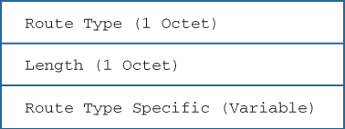
The BGP EVPN overlay specifies the distribution and discovery of VTEP using EVPN. The information is carried as EVPN Inclusive Multicast (IM) NLRI, which has the format shown in Figure 13-10.

Encoding of the IM NLRI is based on “Single Virtual Identifier per EVI,” wherein every VNI is mapped to a unique Ethernet VPN instance (EVI) as follows.
![]() RD: Route distinguisher for the EVPN instance, auto derived
RD: Route distinguisher for the EVPN instance, auto derived
![]() Ethernet Tag ID: VNI for the bridge domain
Ethernet Tag ID: VNI for the bridge domain
![]() IP address length: 1 byte
IP address length: 1 byte
![]() Originating Router’s IP address: VTEP IP address of the advertising endpoint.
Originating Router’s IP address: VTEP IP address of the advertising endpoint.
Advertisement and learning of IP host addresses associated with a VTEP is accomplished via BGP EVPN MAC advertisement NLRI, specified in RFC 7432. The VTEP information is implicitly sent as the BGP next-hop associated with the IP host, and by also providing the VTEP gateway MAC address in the MAC advertisement NLRI, as shown in Figure 13-11.

Encoding of the NLRI is as follows:
![]() RD: Route distinguisher (RD) for the EVI, auto derived
RD: Route distinguisher (RD) for the EVI, auto derived
![]() Ethernet Segment Identifier
Ethernet Segment Identifier
![]() Ethernet Tag ID: VNI for the VRF
Ethernet Tag ID: VNI for the VRF
![]() MAC Address Length: 6 bytes
MAC Address Length: 6 bytes
![]() MAC Address: Router MAC
MAC Address: Router MAC
![]() IP Address Length: 1 byte
IP Address Length: 1 byte
![]() IP Address: Host IP address
IP Address: Host IP address
![]() MPLS Label: 0
MPLS Label: 0
The RT value is either manually configured or autogenerated, which is based on a 2-byte AS number and the VNI value. The route is imported into the correct VLAN or bridge domain based on the import route target configuration.
The design for the VxLAN deployment follows the spine-and-leaf architecture. With VxLAN BGP EVPN solution, the spine nodes are usually configured as the route reflectors and only require the nv overlay feature to be enabled along with BGP. The leaf nodes, on the other hand, require the nv overlay feature along with the vn-segment-vlan-based feature to be enabled. The vn-segment-vlan-based feature is required to map the VLAN to the VNI. The spine can be configured either on a Nexus 9500 or Nexus 7000 switch. The leaf can be configured on Nexus 9300 or on Nexus 7000 or 7700 with F3 and M3 modules.
During the course of this chapter, various components on Nexus 9000 architecture are used from time to time. Some of those components are as follows:
![]() VxLAN Manager: VxLAN Manager is the VxLAN control and management plane component that is responsible for VxLAN local tunnel endpoint configuration, remote endpoint learning, management of Address Resolution Protocol (ARP) suppression, and platform-dependent (PD) programming.
VxLAN Manager: VxLAN Manager is the VxLAN control and management plane component that is responsible for VxLAN local tunnel endpoint configuration, remote endpoint learning, management of Address Resolution Protocol (ARP) suppression, and platform-dependent (PD) programming.
![]() L2RIB: The L2RIB component manages the Layer 2 routing information. The L2RIB component interacts with VxLAN Manager, BGP, Layer 2 Forwarding Manager (L2FM), ARP, and Multicast Forwarding Distribution Manager (MFDM).
L2RIB: The L2RIB component manages the Layer 2 routing information. The L2RIB component interacts with VxLAN Manager, BGP, Layer 2 Forwarding Manager (L2FM), ARP, and Multicast Forwarding Distribution Manager (MFDM).
![]() MFIB: Multicast Forwarding Information Base (MFIB) finds out all VxLAN VNIs that share multicast group and program encapsulation/decapsulation entries for each of the VNI when the VTEP interface is in outgoing interface list (OIL) for a group.
MFIB: Multicast Forwarding Information Base (MFIB) finds out all VxLAN VNIs that share multicast group and program encapsulation/decapsulation entries for each of the VNI when the VTEP interface is in outgoing interface list (OIL) for a group.
![]() AM: Adjacency Manager (AM) performs two tasks:
AM: Adjacency Manager (AM) performs two tasks:
![]() Hosts IP and MAC binding for locally learned hosts
Hosts IP and MAC binding for locally learned hosts
![]() Programs routing information base (RIB) and forwarding information base (FIB) for host route and adjacency binding, respectively
Programs routing information base (RIB) and forwarding information base (FIB) for host route and adjacency binding, respectively
Configuring and Verifying VxLAN BGP EVPN
VxLAN BGP EVPN functionality is supported from the 7.0(3)I1(1) release on NX-OS. Both Nexus 9500 and Nexus 9300 switches support inter-VxLAN routing in hardware. For understanding the configuration and verification of VxLAN BGP EVPN solution, examine the topology shown in Figure 13-12. There is a single spine node that is a Nexus 9508 switch and four leaf nodes that are Nexus 9396 switches. There is a Nexus 5000 switch attached to the Leaf3 and Leaf4 node for VPC. Hosts are attached to Leaf1, Leaf2, and the Nexus 5000 switch. For demonstration purpose, only one spine is used. The other spine is used for RP redundancy with anycast RP.

From the VxLAN EVPN control-plane overview, it is understood that the role of the spine switch is to provide connectivity between the leafs and also act as an EVPN RR. The VxLAN EVPN configuration for the spine switch is performed in a few simple steps:
Step 1. Enable Features. Enable nv overlay and BGP feature on the spine switch. Because the spine provides connectivity for the leaf switches, and not actually for terminating VNIs, the vn-segment-vlan-based feature is not enabled. To enable EVPN AFI supported under BGP, use the command nv overlay evpn.
Step 2. Configure BGP with EVPN AFI. Configure BGP with the appropriate AS number. Enable the l2vpn evpn address-family and then configure the BGP peering with the VTEPS; that is, the leaf switches. The leaf switches act as RR clients.
Note
Use the Interior Gateway Protocol (IGP) and PIM configuration from the VxLAN Flood-and-Learn demonstration because it is the same for the VxLAN BGP EVPN solution.
Example 13-8 demonstrates the configuration of the spine switch (running Nexus 9500).
Example 13-8 EVPN RR Configuration on Nexus 9500 Spine Switch
! Spine Switch
feature nv overlay
feature bgp
!
nv overlay evpn
!
router bgp 100
router-id 192.168.10.10
address-family l2vpn evpn
neighbor 192.168.1.1
remote-as 100
update-source loopback0
address-family l2vpn evpn
send-community both
route-reflector-client
neighbor 192.168.2.2
remote-as 100
update-source loopback0
address-family l2vpn evpn
send-community both
route-reflector-client
Now configure the leaf switches. Perform the following steps for configuring the leaf switches with Layer 2 VNI.
Step 1. Enable Features. Enable nv overlay, vn-segment-vlan-based, and the BGP feature on the leaf switches. To enable EVPN AFI support under BGP, configure the command nv overlay evpn.
Step 2. Create L2 VNI. Create a VLAN and assign VNID to the VLAN using the command nv-segment vnid.
Step 3. Add the L2 VNI to the Overlay with BGP Control Plane and Enable Arp Suppression. Configure the NVE interface. The command host-reachability protocol bgp enables control-plane advertisement of the host IP/MAC address learned on the VNI via BGP EVPN. Under the member VNI, add the multicast group and configure the command suppress-arp to enable ARP suppression. The suppress-arp command is applicable only for L2 VNIs.
Step 4. Configure EVPN with RT Import/Export for each VNI. Configure the EVPN section using the command evpn. Under each VNI, set the RD manually or for auto assignment. Use the command route-target [import | export] rt-value to configure the import and export RT statements.
Step 5. Configure SVI for L2 VNI. Configure the SVIs for each L2 VNI. The SVIs must be part of proper VRF. Also configure the anycast gateway mac-address command on each leaf node. Note that the IP address configured for each L3 VNI should be the same on all VTEPs.
Step 6. Configure BGP with the EVPN AFI. Configure BGP with the appropriate AS number. Enable the l2vpn evpn address-family and then configure the BGP peering with the spine switches that are acting as the RR routers. Under the BGP, also enable the VRF address-family that is configured for the L3 VNI.
Example 13-9 demonstrates the configuration of the leaf nodes Leaf1 and Leaf2, which are running on Nexus 9396 switches.
Example 13-9 VxLAN EVPN Configuration on Leaf Nodes for L2 VNI
Leaf1
feature bgp
feature interface-vlan
feature vn-segment-vlan-based
feature nv overlay
!
nv overlay evpn
!
vlan 100
vn-segment 10000
!
vrf context EVPN-TENANT
!
evpn
vni 10000 l2
rd 10000:1
route-target import 10000:1
route-target export 10000:1
!
interface nve1
no shutdown
source-interface loopback0
host-reachability protocol bgp
member vni 10000
mcast-group 239.1.1.1
suppress-arp
!
fabric forwarding anycast-gateway-mac 0001.0001.0001
interface Vlan100
no shutdown
vrf member EVPN-TENANT
ip address 100.1.1.254/24
fabric forwarding mode anycast-gateway
!
router bgp 100
router-id 192.168.1.1
address-family l2vpn evpn
neighbor 192.168.10.10
description "Peering with Route Reflector"
remote-as 100
update-source loopback0
address-family l2vpn evpn
send-community extended
vrf EVPN-TENANT
address-family ipv4 unicast
advertise l2vpn evpn
Leaf2
feature bgp
feature interface-vlan
feature vn-segment-vlan-based
feature nv overlay
!
nv overlay evpn
!
vlan 100
vn-segment 10000
!
vrf context EVPN-TENANT
!
evpn
vni 10000 l2
rd 10000:1
route-target import 10000:1
route-target export 10000:1
!
interface nve1
no shutdown
source-interface loopback0
host-reachability protocol bgp
member vni 10000
mcast-group 239.1.1.1
suppress-arp
!
fabric forwarding anycast-gateway-mac 0002.0002.0002
! SVI for L2 VNI
interface Vlan100
no shutdown
vrf member EVPN-TENANT
ip address 100.1.1.254/24
fabric forwarding mode anycast-gateway
!
router bgp 100
router-id 192.168.2.2
address-family l2vpn evpn
neighbor 192.168.10.10
remote-as 100
description "Peering with Route Reflector"
update-source loopback0
address-family l2vpn evpn
send-community extended
vrf EVPN-TENANT
address-family ipv4 unicast
advertise l2vpn evpn
Note
For the ARP Suppression functionality to work with BGP EVPN solution, it is required to carve out hardware ternary content-addressable memory (TCAM) resources for the ARP access control list (ACL) by using the command hardware access-list tcam region arp-ether 256. After configuring this command, a reload is required for the resources to be carved out and take effect.
After configuring the NVE interface and the SVI interface, verify the NVE interface status. Example 13-10 examines the status of the NVE interface created on both the leaf nodes.
Example 13-10 NVE Interface Status
Leaf1
Leaf1# show interface nve1
nve1 is up
admin state is up, Hardware: NVE
MTU 1500 bytes
Encapsulation VXLAN
Auto-mdix is turned off
RX
ucast: 0 pkts, 0 bytes - mcast: 0 pkts, 0 bytes
TX
ucast: 0 pkts, 0 bytes - mcast: 0 pkts, 0 bytes
Leaf1# show nve interface
Interface: nve1, State: Up, encapsulation: VXLAN
VPC Capability: VPC-VIP-Only [not-notified]
Local Router MAC: f40f.1b6f.926f
Host Learning Mode: Control-Plane
Source-Interface: loopback0 (primary: 192.168.1.1, secondary: 0.0.0.0)
Leaf2
Leaf1# show interface nve1
nve1 is up
admin state is up, Hardware: NVE
MTU 1500 bytes
Encapsulation VXLAN
Auto-mdix is turned off
RX
ucast: 0 pkts, 0 bytes - mcast: 0 pkts, 0 bytes
TX
ucast: 0 pkts, 0 bytes - mcast: 0 pkts, 0 bytes
Leaf2# show nve interface
Interface: nve1, State: Up, encapsulation: VXLAN
VPC Capability: VPC-VIP-Only [not-notified]
Local Router MAC: 88f0.312a.f2c1
Host Learning Mode: Control-Plane
Source-Interface: loopback0 (primary: 192.168.2.2, secondary: 0.0.0.0)
After the configuration is done, the BGP L2VPN EVPN session comes up. After the session comes up, no prefixes are exchanged unless the locally connected host sends G-ARP or tries to send traffic toward the remote host. This is when the MAC address and the ARP are learned from the host. To verify the BGP EVPN session, use the command show bgp l2vpn evpn summary. When the prefixes are exchanged, for every end host, two BGP NLRIs are exchanged: one NLRI for the MAC address of the host and the other for the MAC and IP address of the host.
Examine the output of the show bgp l2vpn evpn summary and the show bgp l2vpn evpn command in Example 13-11 to verify the EVPN session and prefixes. Use the command show bgp l2vpn evpn vni-id vni-id to view the prefixes in a particular VNI. In Example 13-11, there are two prefixes received from the Leaf2 node. The first highlighted prefix is the MAC address of the host. The second highlighted prefix along with the IP address shows the IP address of the remote host attached to Leaf2.
Example 13-11 BGP L2VPN EVPN Session and Prefix Verification
Leaf1
Leaf1# show bgp l2vpn evpn summary
BGP summary information for VRF default, address family L2VPN EVPN
BGP router identifier 192.168.1.1, local AS number 100
BGP table version is 11, L2VPN EVPN config peers 1, capable peers 1
4 network entries and 4 paths using 784 bytes of memory
BGP attribute entries [2/288], BGP AS path entries [0/0]
BGP community entries [0/0], BGP clusterlist entries [1/4]
Neighbor V AS MsgRcvd MsgSent TblVer InQ OutQ Up/Down State/PfxRcd
192.168.10.10 4 100 69 68 11 0 0 00:58:11 2
! Verifying EVPN Prefixes
Leaf1# show bgp l2vpn evpn
BGP routing table information for VRF default, address family L2VPN EVPN
BGP table version is 11, local router ID is 192.168.1.1
Status: s-suppressed, x-deleted, S-stale, d-dampened, h-history, *-valid, >-best
Path type: i-internal, e-external, c-confed, l-local, a-aggregate, r-redist,
I-injected
Origin codes: i - IGP, e - EGP, ? - incomplete, | - multipath, & - backup
Network Next Hop Metric LocPrf Weight Path
Route Distinguisher: 10000:1 (L2VNI 10000)
*>i[2]:[0]:[0]:[48]:[8c60.4f19.51fc]:[0]:[0.0.0.0]/216
192.168.2.2 100 0 i
*>l[2]:[0]:[0]:[48]:[8c60.4f1b.e43c]:[0]:[0.0.0.0]/216
192.168.1.1 100 32768 i
*>i[2]:[0]:[0]:[48]:[8c60.4f19.51fc]:[32]:[100.1.1.2]/248
192.168.2.2 100 0 i
*>l[2]:[0]:[0]:[48]:[8c60.4f1b.e43c]:[32]:[100.1.1.1]/248
192.168.1.1 100 32768 i
The NVE peers are viewed using the command show nve peers [detail]. This command displays the NVE peer status, Peer’s first VNI, the time when the peer came up, and the provision state (indicates that the hardware is programmed to forward the traffic). Example 13-12 displays the output of the command show nve peers detail.
Leaf1
Leaf1# show nve peers detail
Details of nve Peers:
----------------------------------------
Peer-Ip: 192.168.2.2
NVE Interface : nve1
Peer State : Up
Peer Uptime : 02:32:43
Router-Mac : n/a
Peer First VNI : 10000
Time since Create : 02:32:43
Configured VNIs : 10000
Provision State : add-complete
Route-Update : Yes
Peer Flags : DisableLearn
Learnt CP VNIs : 10000
Peer-ifindex-resp : Yes
----------------------------------------
The MAC address table can also be verified for the MAC address of both the hosts that are part of the L2 VNI. The leaf nodes also learn the ARP information for the local hosts attached in the VRF. Example 13-13 displays the MAC address table for VLAN 100 and the ARP table for VRF EVPN-TENANT. Notice that the first MAC address 8c60.4f19.51fc is learned over the NVE peer that is the node Leaf2. The MAC is learned from L2FM, and the MAC-IP information is learned from ARP.
Example 13-13 MAC Address Table for L2 VNI VLAN
Leaf1
Leaf1# show mac address-table vlan 100
Legend:
* - primary entry, G - Gateway MAC, (R) - Routed MAC, O - Overlay MAC
age - seconds since last seen,+ - primary entry using vPC Peer-Link,
(T) - True, (F) - False
VLAN MAC Address Type age Secure NTFY Ports
---------+-----------------+--------+---------+------+----+------------------
* 100 8c60.4f19.51fc dynamic 0 F F nve1(192.168.2.2)
* 100 8c60.4f1b.e43c dynamic 0 F F Eth1/12
G 100 f40f.1b6f.926f static - F F sup-eth1(R)
! ARP TABLE
Leaf1# show ip arp vrf EVPN-TENANT
IP ARP Table for context EVPN-TENANT
Total number of entries: 1
Address Age MAC Address Interface
100.1.1.1 00:17:52 8c60.4f1b.e43c Vlan100
After the MAC and MAC-IP information is learned, it gets downloaded into L2RIB. Verify the information by using the command show l2route evpn [mac | mac-ip] evi vlan-id. Example 13-14 displays the output of the two commands verifying whether the MAC and MAC-IP information is downloaded to L2RIB.
Example 13-14 Installing MAC and MAC-IP into L2RIB
Leaf1
! MAC Information into L2RIB
Leaf1# show l2route evpn mac evi 100
Mac Address Prod Next Hop (s)
-------------- ------ ---------------
8c60.4f19.51fc BGP 192.168.2.2
8c60.4f1b.e43c Local Eth1/12
! MAC-IP Information into L2RIB
Leaf1# show l2route evpn mac-ip evi 100
Mac Address Prod Host IP Next Hop (s)
-------------- ---- --------------------------------------- ---------------
8c60.4f19.51fc BGP 100.1.1.2 192.168.2.2
8c60.4f1b.e43c HMM 100.1.1.1 N/A
Leaf2
Leaf2# show l2route evpn mac evi 100
Mac Address Prod Next Hop (s)
-------------- ------ ---------------
8c60.4f19.51fc Local Eth1/13
8c60.4f1b.e43c BGP 192.168.1.1
Leaf2# show l2route evpn mac-ip evi 100
Mac Address Prod Host IP Next Hop (s)
-------------- ---- --------------------------------------- ---------------
8c60.4f19.51fc HMM 100.1.1.2 N/A
8c60.4f1b.e43c BGP 100.1.1.1 192.168.1.1
The internal platform-level information on the NVE interface can also be verified. Example 13-15 displays the output of the command show nve internal platform interface nve [number] [detail]. Along with the NVE information, the command also displays the VNI-related information. Notice that the type is set to CP, which means control plane. This command also displays the information about the NVE peers.
Example 13-15 NVE Internal Platform Information
Leaf1
Leaf1# show nve internal platform interface nve 1 detail
Printing Interface ifindex 0x49000001 detail
|======|=========================|===============|===============|=====|=====|
|Intf |State |PriIP |SecIP |Vnis |Peers|
|======|=========================|===============|===============|=====|=====|
|nve1 |UP |192.168.1.1 |0.0.0.0 |1 |1 |
|======|=========================|===============|===============|=====|=====|
SW_BD/VNIs of interface nve1:
================================================
|======|======|=========================|======|====|======|========
|Sw BD |Vni |State |Intf |Type|Vrf-ID|Notified
|======|======|=========================|======|====|======|========
|100 |10000 |UP |nve1 |CP |0 |Yes
|======|======|=========================|======|====|======|========
Peers of interface nve1:
============================================
Peer_ip: 192.168.2.2
Peer-ID : 1
State : UP
Learning : Disabled
TunnelID : 0x0
MAC : 0000.0000.0000
Table-ID : 0x1
Encap : 0x1
Similar to the steps required for an L2 VNI, the L3 VNI can also be configured in a few simple steps:
Step 1. Create VLAN/VNI for L3. Similar to L2 VNI, configure a VLAN for L3 VNI using the command vn-segment under the VLAN configuration mode.
Step 2. Create L3 VRF and link to L2 VNI. Create a VRF and associate the L3 VNI with the tenant VRF routing instance.
Step 3. Create SVI for the L3 VNI and associate it with the L3 VRF. Create an SVI for the L3 VNI with no IP address assigned to it. Associate the VRF created in Step 2.
Step 4. Add L3 VNI to NVE. Add the L3 VNI as a member of the NVE interface using the command member vni vni-id associate-vrf.
Step 5. Add VRF to BGP EVPN. Configure VRF under the BGP with IPv4 address-family and configure the command advertise l2vpn evpn to advertise the EVPN routes to remote peers.
Example 13-16 demonstrates the configuration of the L3 VNI on the Nexus 9300 leaf nodes.
Example 13-16 Configuring L3 VNI on Leaf Nodes
Leaf1
vlan 200
vn-segment 20000
!
vrf context EVPN-TENANT
vni 20000
rd 20000:1
address-family ipv4 unicast
route-target import 20000:1
route-target import 20000:1 evpn
route-target export 20000:1
route-target export 20000:1 evpn
!
interface Vlan200
no shutdown
vrf member EVPN-TENANT
ip forward
!
interface nve1
no shutdown
source-interface loopback0
host-reachability protocol bgp
member vni 20000 associate-vrf
!
interface loopback200
vrf member EVPN-TENANT
ip address 200.1.1.1/32
!
router bgp 100
vrf EVPN-TENANT
address-family ipv4 unicast
network 200.1.1.1/32
advertise l2vpn evpn
Leaf2
vlan 200
vn-segment 20000
!
vrf context EVPN-TENANT
vni 20000
rd 20000:1
address-family ipv4 unicast
route-target import 20000:1
route-target import 20000:1 evpn
route-target export 20000:1
route-target export 20000:1 evpn
!
interface Vlan200
no shutdown
vrf member EVPN-TENANT
ip forward
!
interface nve1
no shutdown
source-interface loopback0
host-reachability protocol bgp
member vni 20000 associate-vrf
!
interface loopback200
vrf member EVPN-TENANT
ip address 200.1.1.2/32
!
router bgp 100
vrf EVPN-TENANT
address-family ipv4 unicast
network 200.1.1.2/32
advertise l2vpn evpn
Because the symmetric IRB requires the introduction of a transit L3 VNI for L3 segmentation service per tenant, after the configuration of L3 VNI, the BGP table imports the host routes and network statement prefixes in the EVPN table as part of the L3 VNI routes. Example 13-17 displays the output of the BGP EVPN table with both the L2 VNI and the L3 VNI information.
Example 13-17 L3 VNI Prefixes in BGP EVPN Table
Leaf1
Leaf1# show bgp l2vpn evpn
BGP routing table information for VRF default, address family L2VPN EVPN
BGP table version is 18, local router ID is 192.168.1.1
Network Next Hop Metric LocPrf Weight Path
Route Distinguisher: 10000:1 (L2VNI 10000)
*>i[2]:[0]:[0]:[48]:[8c60.4f19.51fc]:[0]:[0.0.0.0]/216
192.168.2.2 100 0 i
*>l[2]:[0]:[0]:[48]:[8c60.4f1b.e43c]:[0]:[0.0.0.0]/216
192.168.1.1 100 32768 i
*>i[2]:[0]:[0]:[48]:[8c60.4f19.51fc]:[32]:[100.1.1.2]/272
192.168.2.2 100 0 i
*>l[2]:[0]:[0]:[48]:[8c60.4f1b.e43c]:[32]:[100.1.1.1]/272
192.168.1.1 100 32768 i
Route Distinguisher: 20000:1
*>i[5]:[0]:[0]:[32]:[200.1.1.2]:[0.0.0.0]/224
192.168.2.2 100 0 i
Route Distinguisher: 20000:1 (L3VNI 20000)
*>i[2]:[0]:[0]:[48]:[8c60.4f19.51fc]:[32]:[100.1.1.2]/272
192.168.2.2 100 0 i
*>l[5]:[0]:[0]:[32]:[200.1.1.1]:[0.0.0.0]/224
192.168.1.1 100 32768 i
*>i[5]:[0]:[0]:[32]:[200.1.1.2]:[0.0.0.0]/224
192.168.2.2 100 0 i
Leaf2
Leaf2# show bgp l2vpn evpn
BGP routing table information for VRF default, address family L2VPN EVPN
BGP table version is 23, local router ID is 192.168.2.2
Network Next Hop Metric LocPrf Weight Path
Route Distinguisher: 10000:1 (L2VNI 10000)
*>l[2]:[0]:[0]:[48]:[8c60.4f19.51fc]:[0]:[0.0.0.0]/216
192.168.2.2 100 32768 i
*>i[2]:[0]:[0]:[48]:[8c60.4f1b.e43c]:[0]:[0.0.0.0]/216
192.168.1.1 100 0 i
*>l[2]:[0]:[0]:[48]:[8c60.4f19.51fc]:[32]:[100.1.1.2]/272
192.168.2.2 100 32768 i
*>i[2]:[0]:[0]:[48]:[8c60.4f1b.e43c]:[32]:[100.1.1.1]/272
192.168.1.1 100 0 i
Route Distinguisher: 20000:1
*>i[5]:[0]:[0]:[32]:[200.1.1.1]:[0.0.0.0]/224
192.168.1.1 100 0 i
Route Distinguisher: 20000:1 (L3VNI 20000)
*>i[2]:[0]:[0]:[48]:[8c60.4f1b.e43c]:[32]:[100.1.1.1]/272
192.168.1.1 100 0 i
*>i[5]:[0]:[0]:[32]:[200.1.1.1]:[0.0.0.0]/224
192.168.1.1 100 0 i
*>l[5]:[0]:[0]:[32]:[200.1.1.2]:[0.0.0.0]/224
192.168.2.2 100 32768 i
The EVPN routes are also seen in the Tenant VRF. The routing table shows which routes have been locally learned and others that have been learned over EVPN with VxLAN encapsulation. Example 13-18 examines the Tenant VRF routing table. Note that the tunnelid is nothing but the remote VTEP IP. The hex value 0xc0a80202 represents 192.168.2.2 in decimal format.
Example 13-18 Tenant VRF Routing Table
Leaf1
Leaf1# show ip route vrf EVPN-TENANT
IP Route Table for VRF "EVPN-TENANT"
100.1.1.0/24, ubest/mbest: 1/0, attached
*via 100.1.1.254, Vlan100, [0/0], 11:37:59, direct
100.1.1.1/32, ubest/mbest: 1/0, attached
*via 100.1.1.1, Vlan100, [190/0], 11:21:00, hmm
100.1.1.2/32, ubest/mbest: 1/0
*via 192.168.2.2%default, [200/0], 08:10:21, bgp-100, internal,
tag 100 (evpn) segid: 20000 tunnelid: 0xc0a80202 encap: VXLAN
100.1.1.254/32, ubest/mbest: 1/0, attached
*via 100.1.1.254, Vlan100, [0/0], 11:37:59, local
200.1.1.1/32, ubest/mbest: 2/0, attached
*via 200.1.1.1, Lo200, [0/0], 07:54:28, local
*via 200.1.1.1, Lo200, [0/0], 07:54:28, direct
200.1.1.2/32, ubest/mbest: 1/0
*via 192.168.2.2%default, [200/0], 05:59:49, bgp-100, internal,
tag 100 (evpn) segid: 20000 tunnelid: 0xc0a80202 encap: VXLAN
The command show bgp l2vpn evpn ip-address, where ip-address is the end host IP address, provides more detailed information about the prefix. In this command, there are two labels received for the prefix. The first label is the L2 VNI vni-id, and the second label is the L3 VNI vni-id. Also, as explained previously, the router MAC is sent as the destination MAC address for VxLAN encapsulation. This command output holds that information as well. Example 13.19 displays the output of the host prefix 100.1.1.2, which is connected to Leaf2 node.
Example 13-19 EVPN Host Prefix
Leaf1
Leaf1# show bgp l2vpn evpn 100.1.1.12
BGP routing table information for VRF default, address family L2VPN EVPN
Leaf1# show bgp l2vpn evpn 100.1.1.2
BGP routing table information for VRF default, address family L2VPN EVPN
Route Distinguisher: 10000:1 (L2VNI 10000)
BGP routing table entry for [2]:[0]:[0]:[48]:[8c60.4f19.51fc]:[32]:[100.1.1.2]
/272, version 16
Paths: (1 available, best #1)
Flags: (0x00021a) on xmit-list, is in l2rib/evpn, is not in HW, , is locked
Advertised path-id 1
Path type: internal, path is valid, imported same remote RD, is best path,
no labeled nexthop
AS-Path: NONE, path sourced internal to AS
192.168.2.2 (metric 5) from 192.168.10.10 (192.168.10.10)
Origin IGP, MED not set, localpref 100, weight 0
Received label 10000 20000
Extcommunity: RT:10000:1 RT:20000:1 ENCAP:8 Router MAC:88f0.312a.f2c1
Originator: 192.168.2.2 Cluster list: 192.168.10.10
Path-id 1 not advertised to any peer
Route Distinguisher: 20000:1 (L3VNI 20000)
BGP routing table entry for [2]:[0]:[0]:[48]:[8c60.4f19.51fc]:[32]:[100.1.1.2]
/272, version 17
Paths: (1 available, best #1)
Flags: (0x00021a) on xmit-list, is in l2rib/evpn, is not in HW,
Advertised path-id 1
Path type: internal, path is valid, is best path, no labeled nexthop
Imported from
10000:1:[2]:[0]:[0]:[48]:[8c60.4f19.51fc]:[32]:[100.1.1.2]/144 (VNI 10000)
AS-Path: NONE, path sourced internal to AS
192.168.2.2 (metric 5) from 192.168.10.10 (192.168.10.10)
Origin IGP, MED not set, localpref 100, weight 0
Received label 10000 20000
Extcommunity: RT:10000:1 RT:20000:1 ENCAP:8 Router MAC:88f0.312a.f2c1
Originator: 192.168.2.2 Cluster list: 192.168.10.10
Path-id 1 not advertised to any peer
After adding the L3VNI, the NVE internal platform information also shows the Tunnel Id and the Router MAC address. Also when viewing the show nve peers [detail] command, the peer flags are set to RmacL2Rib, TunnelPD, and DisableLearn, which was earlier set to just DisableLearn without the L2 VNI. Example 13-20 shows the NVE internal platform information for the NVE interface and the NVE peer information.
Example 13-20 NVE Internal Platform Information and NVE Peers
Leaf1
Leaf1# show nve internal platform interface nve 1 detail
Printing Interface ifindex 0x49000001 detail
|======|=========================|===============|===============|=====|=====|
|Intf |State |PriIP |SecIP |Vnis |Peers|
|======|=========================|===============|===============|=====|=====|
|nve1 |UP |192.168.1.1 |0.0.0.0 |2 |1 |
|======|=========================|===============|===============|=====|=====|
SW_BD/VNIs of interface nve1:
================================================
|======|======|=========================|======|====|======|========
|Sw BD |Vni |State |Intf |Type|Vrf-ID|Notified
|======|======|=========================|======|====|======|========
|100 |10000 |UP |nve1 |CP |0 |Yes
|200 |20000 |UP |nve1 |CP |3 |Yes
|======|======|=========================|======|====|======|========
Peers of interface nve1:
============================================
Peer_ip: 192.168.2.2
Peer-ID : 1
State : UP
Learning : Disabled
TunnelID : 0xc0a80202
MAC : 88f0.312a.f2c1
Table-ID : 0x1
Encap : 0x1
Leaf1# show nve peers detail
Details of nve Peers:
----------------------------------------
Peer-Ip: 192.168.2.2
NVE Interface : nve1
Peer State : Up
Peer Uptime : 11:40:04
Router-Mac : 88f0.312a.f2c1
Peer First VNI : 10000
Time since Create : 11:40:04
Configured VNIs : 10000,20000
Provision State : add-complete
Route-Update : Yes
Peer Flags : RmacL2Rib, TunnelPD, DisableLearn
Learnt CP VNIs : 10000,20000
Peer-ifindex-resp : Yes
Another scenario that is heavily seen in production deployment is when virtual port channel (VPC) is terminated on the leaf nodes and the host is attached across the VPC. In such situations there are few things that require special attention while configuring the VTEP.
A pair of VPC peers are seen as a single VTEP node to other peer VTEPs. A secondary IP is configured on the loopback address for the VPC running leaf nodes. The secondary IP address is same on both the primary VPC and the secondary VPC peer. Nexus 9000 uses the secondary IP to create a virtual VTEP. The rest of the configuration remains the same as the non-VPC examples. Example 13-21 illustrates the partial configuration on the leaf node Leaf3 and Leaf4 running VPC between them.
Example 13-21 VxLAN EVPN Configuration on VPC Peers
Leaf3
vlan 100
vn-segment 10000
vlan 200
vn-segment 20000
!
vrf context EVPN-TENANT
vni 20000
rd 20000:1
address-family ipv4 unicast
route-target import 20000:1
route-target import 20000:1 evpn
route-target export 20000:1
route-target export 20000:1 evpn
!
evpn
vni 10000 l2
rd 10000:1
route-target import 10000:1
route-target export 10000:1
!
vpc domain 10
peer-switch
peer-keepalive destination 10.1.34.4 source 10.1.34.3
delay restore 60
peer-gateway
ipv6 nd synchronize
ip arp synchronize
!
interface loopback0
ip address 192.168.3.3/32
ip address 192.168.100.100/32 secondary
ip router ospf 100 area 0.0.0.0
ip pim sparse-mode
!
! Output omitted for brevity
!
router bgp 100
router-id 192.168.3.3
address-family ipv4 unicast
address-family l2vpn evpn
neighbor 192.168.10.10
remote-as 100
description Peering with Route Reflector
update-source loopback0
address-family l2vpn evpn
send-community extended
vrf EVPN-TENANT
address-family ipv4 unicast
advertise l2vpn evpn
Leaf4
vlan 100
vn-segment 10000
vlan 200
vn-segment 20000
!
vrf context EVPN-TENANT
vni 20000
rd 20000:1
address-family ipv4 unicast
route-target import 20000:1
route-target import 20000:1 evpn
route-target export 20000:1
route-target export 20000:1 evpn
!
evpn
vni 10000 l2
rd 10000:1
route-target import 10000:1
route-target export 10000:1
!
vpc domain 10
peer-switch
peer-keepalive destination 10.1.34.3 source 10.1.34.4
delay restore 60
peer-gateway
ipv6 nd synchronize
ip arp synchronize
!
interface loopback0
ip address 192.168.3.3/32
ip address 192.168.100.100/32 secondary
ip router ospf 100 area 0.0.0.0
ip pim sparse-mode
!
! Output omitted for brevity
!
router bgp 100
router-id 192.168.4.4
address-family ipv4 unicast
address-family l2vpn evpn
neighbor 192.168.10.10
remote-as 100
description Peering with Route Reflector
update-source loopback0
address-family l2vpn evpn
send-community extended
vrf EVPN-TENANT
address-family ipv4 unicast
advertise l2vpn evpn
Note
Explanation on how VPC feature works is outside the scope of this book. Refer to Cisco documentation for understanding VPC.
After it is configured, the NVE internal platform information shows both the primary as well as the secondary IP. The remote VTEPs show the NVE peering formed over the secondary IP. Example 13-22 displays the NVE peers and the NVE internal platform information on the leaf node running VPC.
Example 13-22 NVE Internal Platform Detail
Leaf3
Leaf3# show nve internal platform interface nve1 detail
Printing Interface ifindex 0x49000001 detail
|======|=========================|===============|===============|=====|=====|
|Intf |State |PriIP |SecIP |Vnis |Peers|
|======|=========================|===============|===============|=====|=====|
|nve1 |UP |192.168.3.3 |192.168.100.100|2 |2 |
|======|=========================|===============|===============|=====|=====|
SW_BD/VNIs of interface nve1:
================================================
|======|======|=========================|======|====|======|========
|Sw BD |Vni |State |Intf |Type|Vrf-ID|Notified
|======|======|=========================|======|====|======|========
|100 |10000 |UP |nve1 |CP |0 |Yes
|200 |20000 |UP |nve1 |CP |3 |Yes
|======|======|=========================|======|====|======|========
Peers of interface nve1:
============================================
Peer_ip: 192.168.1.1
Peer-ID : 2
State : UP
Learning : Disabled
TunnelID : 0xc0a80101
MAC : f40f.1b6f.926f
Table-ID : 0x1
Encap : 0x1
Peer_ip: 192.168.2.2
Peer-ID : 1
State : UP
Learning : Disabled
TunnelID : 0xc0a80202
MAC : 88f0.312a.f2c1
Table-ID : 0x1
Encap : 0x1
Leaf3# show nve peers detail
Details of nve Peers:
----------------------------------------
Peer-Ip: 192.168.1.1
NVE Interface : nve1
Peer State : Up
Peer Uptime : 01:37:25
Router-Mac : f40f.1b6f.926f
Peer First VNI : 20000
Time since Create : 01:37:25
Configured VNIs : 10000,20000
Provision State : add-complete
Route-Update : Yes
Peer Flags : RmacL2Rib, TunnelPD, DisableLearn
Learnt CP VNIs : 10000,20000
Peer-ifindex-resp : Yes
----------------------------------------
Peer-Ip: 192.168.2.2
NVE Interface : nve1
Peer State : Up
Peer Uptime : 01:37:25
Router-Mac : 88f0.312a.f2c1
Peer First VNI : 20000
Time since Create : 01:37:25
Configured VNIs : 10000,20000
Provision State : add-complete
Route-Update : Yes
Peer Flags : RmacL2Rib, TunnelPD, DisableLearn
Learnt CP VNIs : 20000
Peer-ifindex-resp : Yes
Leaf1
Leaf1# show nve peers detail
Details of nve Peers:
----------------------------------------
Peer-Ip: 192.168.2.2
NVE Interface : nve1
Peer State : Up
Peer Uptime : 1d06h
Router-Mac : 88f0.312a.f2c1
Peer First VNI : 10000
Time since Create : 1d06h
Configured VNIs : 10000,20000
Provision State : add-complete
Route-Update : Yes
Peer Flags : RmacL2Rib, TunnelPD, DisableLearn
Learnt CP VNIs : 20000
Peer-ifindex-resp : Yes
----------------------------------------
Peer-Ip: 192.168.100.100
NVE Interface : nve1
Peer State : Up
Peer Uptime : 02:36:18
Router-Mac : 88f0.312b.9e4d
Peer First VNI : 10000
Time since Create : 02:36:18
Configured VNIs : 10000,20000
Provision State : add-complete
Route-Update : Yes
Peer Flags : RmacL2Rib, TunnelPD, DisableLearn
Learnt CP VNIs : 10000,20000
Peer-ifindex-resp : Yes
So far, all the previous examples are shown with BGP EVPN running with a multicast core. With BGP EVPN solution with multicast core, the peer discovery is done using the BGP Remote Next-Hop (BGP-RnH). BGP EVPN solution also supports unicast core with the IR method. As discussed earlier, there are two methods with IR:
![]() Static IR
Static IR
![]() IR-based BGP-EVPN
IR-based BGP-EVPN
With static ingress replication, the peers are statically configured, whereas with BGP EVPN with IR peer learning, the peer discovery is done using BGP inclusive multicast Ethernet tag (BGP-IMET) NLRI. Figure 13-13 examines the various host learning and peer-discovery mechanism and their respective configuration.

To further understand how the output differs for the BGP EVPN with IR method, examine the configuration shown in Example 13-23. Two VLANs are created: VLAN 150 mapped to VNI 15000 and VLAN 151 mapped to VNI 15001. The VNI 15000 is a L2 VNI, and VNI 15001 is an L3 VNI; both are part of tenant VRF EVPN-IR-TENANT. The IR is enabled using the command ingress-replication protocol bgp under the L2 VNI configuration.
Example 13-23 BGP EVPN Configuration with IR Method
Leaf1 and Leaf2
interface nve1
no shutdown
source-interface loopback0
host-reachability protocol bgp
member vni 15000
ingress-replication protocol bgp
member vni 15001 associate-vrf
When the EVPN prefixes are exchanged between the two peers, they not only share the host routes, but they also advertise VTEP IP into the BGP EVPN table as a Type 3 (IMET) route. Example 13-24 displays the BGP EVPN table for hosts in VLAN segment 150 along with the VTEP IP information. In the following example, notice that the VTEP-IP 192.168.2.2 is received as a Type 3 route. The prefix also shown the Tunnel type as Ingress Replication.
Example 13-24 BGP EVPN Table with IR Method
Leaf1
Leaf1# show bgp l2vpn evpn vni-id 15000
BGP routing table information for VRF default, address family L2VPN EVPN
BGP table version is 32, local router ID is 192.168.1.1
Status: s-suppressed, x-deleted, S-stale, d-dampened, h-history, *-valid, >-best
Path type: i-internal, e-external, c-confed, l-local, a-aggregate, r-redist,
I-injected
Origin codes: i - IGP, e - EGP, ? - incomplete, | - multipath, & - backup
Network Next Hop Metric LocPrf Weight Path
Route Distinguisher: 192.168.1.1:32917 (L2VNI 15000)
*>i[2]:[0]:[0]:[48]:[8c60.4f19.51fc]:[0]:[0.0.0.0]/216
192.168.2.2 100 0 i
*>l[2]:[0]:[0]:[48]:[8c60.4f1b.e43c]:[0]:[0.0.0.0]/216
192.168.1.1 100 32768 i
*>i[2]:[0]:[0]:[48]:[8c60.4f19.51fc]:[32]:[150.1.1.2]/272
192.168.2.2 100 0 i
*>l[2]:[0]:[0]:[48]:[8c60.4f1b.e43c]:[32]:[150.1.1.1]/272
192.168.1.1 100 32768 i
*>l[3]:[0]:[32]:[192.168.1.1]/88
192.168.1.1 100 32768 i
*>i[3]:[0]:[32]:[192.168.2.2]/88
192.168.2.2 100 0 i
Leaf2# show bgp l2vpn evpn 192.168.2.2
BGP routing table information for VRF default, address family L2VPN EVPN
Route Distinguisher: 192.168.2.2:32917 (L2VNI 15000)
BGP routing table entry for [3]:[0]:[32]:[192.168.2.2]/88, version 26
Paths: (1 available, best #1)
Flags: (0x00000a) on xmit-list, is not in l2rib/evpn
Advertised path-id 1
Path type: local, path is valid, is best path, no labeled nexthop
AS-Path: NONE, path locally originated
192.168.2.2 (metric 0) from 0.0.0.0 (192.168.2.2)
Origin IGP, MED not set, localpref 100, weight 32768
Extcommunity: RT:100:15000
PMSI Tunnel Attribute:
flags: 0x00, Tunnel type: Ingress Replication
Label: 15000, Tunnel Id: 192.168.2.2
Path-id 1 advertised to peers:
192.168.10.10
The IMET route can be seen in the L2RIB using the command show l2route evpn imet evi VLAN-ID. This command displays both the VTEP IPs: one that is of the local VTEP and the other of the remote VTEP. Also, when looking at the VNI 15000, notice that there is no multicast group listed for the VNI, and the host learning is done via UnicastBGP. This information is seen using the command show nve vni vni-id. Example 13-25 displays the IMET route and the VNI information using the preceding commands. Notice in the output, the NVI 15000 is running with a unicast core but the peer learning mode is again via BGP.
Example 13-25 IMET Route and VNI Information
Leaf1
Leaf1# show l2route evpn imet evi 1150
VNI Prod Originating Router IP Addr
----------- ----- ---------------------------------------
Leaf1# show l2route evpn imet evi 150
VNI Prod Originating Router IP Addr
----------- ----- ---------------------------------------
15000 BGP 192.168.2.2
15000 VXLAN 192.168.1.1
Leaf1# show nve vni 15000
Codes: CP - Control Plane DP - Data Plane
UC - Unconfigured SA - Suppress ARP
Interface VNI Multicast-group State Mode Type [BD/VRF] Flags
--------- -------- ----------------- ----- ---- ------------------ -----
nve1 15000 UnicastBGP Up CP L2 [150]
The IMET route information can also be verified in the NVE event-history information, which is seen by using the command show nve internal event-history event. Example 13-26 shows that the IMET notification is received by the leaf node for the remote VTEP. The output of the command show nve internal event-history event is in reverse direction; that is, the more recent information is added on top of the output. In the following output, it is seen that the IMET notification is received for the remote VTEP IP for VLAN 150 and VNI 15000. Then the peer is added for the VNI. Finally, the hardware is programmed for the discovered peer when the state is set to add-complete. The VTEP IP is added to the VNI flood list (FL). The VNI FL can be viewed using the command show l2route evpn fl all.
Example 13-26 NVE Event-History Information
Leaf1
Leaf1# show nve internal event-history events | in IMET
[102] [9403]: Adding FL 192.168.2.2 in position 0 to VNI 15000
[102] [9403]: First Entry: Adding FL 192.168.2.2 for VNI 15000
[102] [9403]: nve_pi_peer_discovered Processed peer 192.168.2.2
[State:add-complete] create-ts:00:10:18 add request on vni 15000 to PD
on nve1 learn-type:[CP]->[CP] src IMET [mac-unchanged]
[102] [9403]: XOS_EVT: nve_peer_vni_sdb_update: Add peer VNI node to SDB
ip:192.168.2.2 vni:15000 learn-src:IMET mac:0000.0000.0000
[102] [9403]: XOS_EVT: nve_peer_vni_add: Add peer VNI node ip:192.168.2.2
vni:15000 learn-src:IMET mac:0000.0000.0000 on intf:0x49000001
[102] [9403]: nve_pi_peer_discovered Peer 192.168.2.2 discovery notification
on VNI 15000 ready:Yes on intf nve1 src:IMET type:CP mac:0000.0000.0000
tunnel-id:0x0 peer ID:0 disable-learning: 1
[102] [9403]: nve_vni_fl_peer_add_or_delete: ADD peer 192.168.2.2 for all
vni:15000-15000 [source:IMET]
[102] [9403]: Got IMET notification 192.168.2.2 for BD 150 and vni 15000.
Operation: ADD
[102] [9395]: IMET route for topo 150 [vni 15000] added to L2RIB
[102] [9395]: IMET Registration for topo 150 added to L2RIB
! VNI Flood List
Leaf1# show l2route evpn fl all
Topology ID Peer-id Flood List Service Node
----------- ----------- --------------- ------------
150 1 192.168.2.2 no
Troubleshooting VxLAN BGP EVPN
Now that you have an understanding of how VxLAN BGP EVPN works and the list of commands that can be used to verify whether VxLAN BGP EVPN is working fine, troubleshooting VxLAN BGP EVPN becomes fairly simple on Nexus 9000. The Nexus platforms running NX-OS code are designed to ease troubleshooting and debugging using event-history data that is available for almost all the components and features running on the system.
The troubleshooting of L2 VNI; that is, the MAC learning on both the local as well as the remote VTEP, can be broken down into a few simple steps and can be verified using various event-history commands on the leaf nodes. To troubleshoot the MAC address advertisement via BGP EVPN and installation in the hardware, use the packet flow and the steps that follow:
Step 1. The host sends an ARP request for the remote host. The MAC address is learned on the VLAN for the local host. The MAC address information is sent to the Layer 2 Forwarding Manager (L2FM) component of the system. This information can be viewed using the command show system internal l2fm event-history debugs | include mac-address. The mac-address variable is the MAC address of the locally attached host.
Step 2. The L2FM component then sends a notification about the L2VNI and MAC address to the Layer 2 Routing Information Base (L2RIB). The information on the L2RIB that is received from L2FM is viewed by using the command show system internal l2rib event-history mac | include mac-address.
Step 3. The L2RIB then sends the L2 VNI and MAC address information to BGP L2VPN component, which is then advertised to the remote VTEP. BGP builds the L2 NLRI information with the local host MAC received:
![]() Prefix—0
Prefix—0
![]() MAC—Host MAC Address
MAC—Host MAC Address
![]() Label1—0
Label1—0
![]() Label2—L2 VNI-ID
Label2—L2 VNI-ID
![]() BD-RT—Configured RT
BD-RT—Configured RT
![]() NH—VTEP-IP
NH—VTEP-IP
The Type 2 NLRI is then sent to the remote VTEP as part of the update.
Step 4. On receiving the update, the remote VTEP stores the information in the L2VPN EVPN table. Apart from viewing the information on the BGP EVPN table, the route import on the remote VTEP is verified by using the command show bgp internal event-history events | include mac-address. The command is executed on the remote VTEP (Leaf2) and mac-address of the host attached to Leaf1 can be used as a filter option.
Step 5. The BGP process on the remote VTEP sends Peer information and VNI notification to the VxLAN manager. This information is verified using the command show nve internal bgp rnh database and also from the event-history logs using the command show nve internal event-history event. It also adds VNI and the MAC address of the remote host learned from VTEP Leaf1 with the Next-Hop set to Leaf1.
Step 6. The VxLAN manager then programs the hardware; that is, the data plane, and also allocates the Peer ID, which is then sent to L2RIB. The information from VxLAN Manager is sent to the Unicast RIB (URIB) / Unicast Forwarding Distribution Manager (UFDM) process which is used to program the FIB. The forwarding information can be viewed using the command show forwarding nv3 l3 peers and the command show forwarding nve l3 adjacency tunnel tunnel-id, where the tunnel-id is received from the first command. The L2RIB, on the other hand, adds the VNI and the MAC address information in the L2FM table, which contains an entry consisting of the MAC address and the next-hop Peer ID (Remote VTEP – Leaf1).
The previously mentioned steps make it easy to figure out which component on the system is causing a problem. The following steps can be used to troubleshoot the L3 VNI route advertisement and installation:
Step 1. A host attached to a VTEP sends an ARP request. The VTEP receives the ARP request and updates its ARP table for the VLAN.
Step 2. After the ARP table is updated, the information is passed onto an AM, which installs the adjacency for the local host. This is viewed by using the command show forwarding vrf vrf-name adjacency.
Step 3. The AM then sends an adjacency notification to the Host Mobility Manager (HMM) with MAC+IP also known as the combo routes. Because the host MAC needs to be carried in a BGP update along with the host IP, HMM publishes the combo route into the L2RIB. Use the command show system internal l2rib event-history mac-ip to view the combo route in L2RIB.
Step 4. The L2RIB then sends the combo route along with the L3 VNI to BGP. The BGP uses the information to prepare its L2 + L3 NLRI, which consists of the following fields:
![]() Prefix—Host-IP
Prefix—Host-IP
![]() MAC—Host MAC
MAC—Host MAC
![]() Label1—L3VNI
Label1—L3VNI
![]() Label2—L2VNI
Label2—L2VNI
![]() VRF-RT
VRF-RT
![]() BD-RT
BD-RT
![]() NH—VTEP-IP
NH—VTEP-IP
![]() Remote Next-Hop (RNH)—Router MAC (RMAC)
Remote Next-Hop (RNH)—Router MAC (RMAC)
The L2 + L3 NLRI is sent as an update to the remote VTEP.
Step 5. The update received on the remote node is viewed by using the command show bgp l2vpn evpn ip-address; where the ip-address is of the host connected to Leaf1 node. The BGP update has the encapsulation as VxLAN; that is, of value 8. BGP, on receiving an update on remote VTEP, updates two components. First, it updates the URIB with VRF, Host-IP, L3 VNI, and VTEP-IP information. Second, it updates the VxLAN Manager with Peer information and VNI and RMAC notification.
Step 6. The information in the URIB is used by UFDM along with the information from VxLAN manager, which programs the data plane with the encapsulation and decapsulation information for the L3 VNI. The VxLAN manager also sends RMAC to UFDM and allocates the Peer-ID.
Step 7. VxLAN manager, on the other hand, sends the Peer-ID notification to the L2RIB. During this time, the VNI is set with the next-hop of the Peer-ID.
Step 8. The L2RIB then updates the L2FM to update the MAC address table.
Note
Data plane or platform troubleshooting for VxLAN EVPN is outside the scope of this book.
Summary
This chapter discussed how VxLAN works and plays a crucial role in the next-generation data centers. As defined in RFC 7348, this chapter described how VxLAN Flood-and-Learn mechanism works. This chapter also briefly talks about the IR method, which uses unicast core instead of multicast. To overcome the challenges faced because of both VxLAN flood-and-learn and IR mechanisms, the VxLAN BGP EVPN solution was developed. This chapter explains how the BGP EVPN solution is used to carry VxLAN Host routes across the VTEPs and provide scalability to VxLAN deployments. VxLAN BGP EVPN provides features such as the following:
![]() Less flooding required
Less flooding required
![]() Dynamic peer VTEP discovery
Dynamic peer VTEP discovery
![]() Stability (no timing out of BUM groups)
Stability (no timing out of BUM groups)
BGP EVPN primarily carries five types of routes:
![]() Route Type 1—Ethernet Auto-Discovery route
Route Type 1—Ethernet Auto-Discovery route
![]() Route Type 2—MAC advertisement route (carries L2 VNI MAC / MAC-IP)
Route Type 2—MAC advertisement route (carries L2 VNI MAC / MAC-IP)
![]() Route Type 3—Inclusive multicast route (EVPN IR and peer discovery)
Route Type 3—Inclusive multicast route (EVPN IR and peer discovery)
![]() Route Type 4—Ethernet segment route
Route Type 4—Ethernet segment route
![]() Route Type 5—IP Prefix Route (L3 VNI route)
Route Type 5—IP Prefix Route (L3 VNI route)
VxLAN EVPN supports both multicast as well as unicast underlay networks between the spine and leaf, but the peer discovery is done using BGP EVPN. This chapter discussed various configuration and verification commands that are used for troubleshooting VxLAN EVPN. Finally, the chapter examined the flow of packets across various components in VxLAN EVPN deployment.
References
RFC 7348, Virtual eXtensible Local Area Network (VxLAN), M. Mahalingam, D. Dutt, K. Duda, P. Agarwal, L. Kreegar, T. Sridhar, M. Bursell, C. Wright, IETF, https://tools.ietf.org/html/rfc7348, August 2014.
RFC 7432, BGP MPLS-Based Ethernet VPN, A. Sajassi, R. Aggarwal, Arktan, N. Bitar, A. Isaac, J. Uttaro, J. Drake, W. Henderickx, IETF, https://tools.ietf.org/html/rfc7432, February 2015.
RFC 7209, Requirements for Ethernet VPN (EVPN), A. Sajassi, R. Aggarwal, Arktan, N. Bitar, A. Isaac, J. Uttaro, W. Henderickx. IETF, https://tools.ietf.org/html/rfc7209, May 2014.
VxLAN Network with MP-BGP EVPN Control Plane Design Guide, Cisco, http://www.cisco.com/c/en/us/products/collateral/switches/nexus-9000-series-switches/guide-c07-734107.html.