Chapter 1. BGP Fundamentals
The following topics are covered in this chapter:
![]() BGP Messages and Inter-Router Communication
BGP Messages and Inter-Router Communication
![]() Basic BGP Configuration for IOS, IOS XR, and NX-OS
Basic BGP Configuration for IOS, IOS XR, and NX-OS
![]() IBGP Rules
IBGP Rules
![]() EBGP Rules
EBGP Rules
![]() BGP Route Aggregation
BGP Route Aggregation
A router’s primary function is to move packets from one network to a different network. A router learns about unattached networks through static configuration or through dynamic routing protocols that distribute network topology information between routers. Routers try to select the best loop-free path in a network based on the destination network. Link flaps, router crashes, and other unexpected events could impact the best path, so the routers must exchange information with each other so that the network topology updates during these types of events.
Routing protocols are classified as either an Interior Gateway Protocol (IGP) or an Exterior Gateway Protocol (EGP), which indicates whether the protocol is designed for exchanging routes within an organization or between organizations. In IGP protocols, all routers use a common logic within the routing domain to find the shortest path to reach a destination. EGP protocols may require a unique routing policy for every external organization that it exchanges routes.
Border Gateway Protocol
RFC 1654 defines Border Gateway Protocol (BGP) as an EGP standardized path-vector routing protocol that provides scalability, flexibility, and network stability. When BGP was created, the primary design consideration was for IPv4 inter-organization connectivity on public networks, such as the Internet, or private dedicated networks. BGP is the only protocol used to exchange networks on the Internet, which has more than 600,000 IPv4 routes and continues to grow. BGP does not advertise incremental updates or refresh network advertisements like OSPF or ISIS. BGP prefers stability within the network, because a link flap could result in route computation for thousands of routes.
From the perspective of BGP, an autonomous system (AS) is a collection of routers under a single organization’s control, using one or more IGPs, and common metrics to route packets within the AS. If multiple IGPs or metrics are used within an AS, the AS must appear consistent to external ASs in routing policy. An IGP is not required within an AS, and could use BGP as the only routing protocol in it, too.
Autonomous System Numbers
Organizations requiring connectivity to the Internet must obtain an Autonomous System Number (ASN). ASNs were originally 2 bytes (16 bit) providing 65,535 ASNs. Due to exhaustion, RFC 4893 expands the ASN field to accommodate 4 bytes (32 bit). This allows for 4,294,967,295 unique ASNs, providing quite a leap from the original 65,535 ASNs.
Two blocks of private ASNs are available for any organization to use as long as they are never exchanged publicly on the Internet. ASNs 64,512–65,535 are private ASNs within the 16-bit ASN range, and 4,200,000,000–4,294,967,294 are private ASNs within the extended 32-bit range.
The Internet Assigned Numbers Authority (IANA) is responsible for assigning all public ASNs to ensure that they are globally unique. IANA requires the following items when requesting a public ASN:
![]() Proof of a publicly allocated network range
Proof of a publicly allocated network range
![]() Proof that Internet connectivity is provided through multiple connections
Proof that Internet connectivity is provided through multiple connections
![]() Need for a unique route policy from your providers
Need for a unique route policy from your providers
In the event that an organization does not meet those guidelines, it should use the ASN provided by its service provider.
Note
It is imperative that you use only the ASN assigned by IANA, the ASN assigned by your service provider, or private ASNs. Using another organization’s ASN without permission could result in traffic loss and cause havoc on the Internet.
Path Attributes
BGP attaches path attributes (PA) associated with each network path. The PAs provide BGP with granularity and control of routing policies within BGP. The BGP prefix PAs are classified as follows:
![]() Well-known mandatory
Well-known mandatory
![]() Well-known discretionary
Well-known discretionary
![]() Optional transitive
Optional transitive
![]() Optional nontransitive
Optional nontransitive
Per RFC 4271, well-known attributes must be recognized by all BGP implementations. Well-known mandatory attributes must be included with every prefix advertisement, whereas well-known discretionary attributes may or may not be included with the prefix advertisement.
Optional attributes do not have to be recognized by all BGP implementations. Optional attributes can be set so that they are transitive and stay with the route advertisement from AS to AS. Other PAs are nontransitive and cannot be shared from AS to AS. In BGP, the Network Layer Reachability Information (NLRI) is the routing update that consists of the network prefix, prefix length, and any BGP PAs for that specific route.
Loop Prevention
BGP is a path vector routing protocol and does not contain a complete topology of the network-like link state routing protocols. BGP behaves similar to distance vector protocols to ensure a path is loop free.
The BGP attribute AS_PATH is a well-known mandatory attribute and includes a complete listing of all the ASNs that the prefix advertisement has traversed from its source AS. The AS_PATH is used as a loop prevention mechanism in the BGP protocol. If a BGP router receives a prefix advertisement with its AS listed in the AS_PATH, it discards the prefix because the router thinks the advertisement forms a loop.
Address Families
Originally, BGP was intended for routing of IPv4 prefixes between organizations, but RFC 2858 added Multi-Protocol BGP (MP-BGP) capability by adding extensions called address-family identifier (AFI). An address-family correlates to a specific network protocol, such as IPv4, IPv6, and the like, and additional granularity through a subsequent address-family identifier (SAFI), such as unicast and multicast. MBGP achieves this separation by using the BGP path attributes (PAs) MP_REACH_NLRI and MP_UNREACH_NLRI. These attributes are carried inside BGP update messages and are used to carry network reachability information for different address families.
Some network engineers refer to Multi-Protocol BGP as MP-BGP, and other network engineers use the term MBGP. Both terms are the same thing.
Network engineers and vendors continue to add functionality and feature enhancements to BGP. BGP now provides a scalable control plane for signaling for overlay technologies like MPLS VPNs, IPsec Security Associations, and Virtual Extensible LAN (VXLAN). These overlays can provide Layer 3 connectivity via MPLS L3VPNs, or Layer 2 connectivity via MPLS L2VPNs (L2VPN), such as Virtual Private LAN Service (VPLS) or Ethernet VPNs (EVPNs).
Every address-family maintains a separate database and configuration for each protocol (address-family + subaddress family) in BGP. This allows for a routing policy in one address-family to be different from a routing policy in a different address family even though the router uses the same BGP session to the other router. BGP includes an AFI and a SAFI with every route advertisement to differentiate between the AFI and SAFI databases. Table 1-1 provides a small list of common AFI and SAFIs.

BGP Sessions
A BGP session refers to the established adjacency between two BGP routers. BGP sessions are always point-to-point and are categorized into two types:
![]() Internal BGP (IBGP): Sessions established with an IBGP router that are in the same AS or participate in the same BGP confederation. IBGP sessions are considered more secure, and some of BGP’s security measures are lowered in comparison to EBGP sessions. IBGP prefixes are assigned an administrative distance (AD) of 200 upon installing into the router’s routing information base (RIB).
Internal BGP (IBGP): Sessions established with an IBGP router that are in the same AS or participate in the same BGP confederation. IBGP sessions are considered more secure, and some of BGP’s security measures are lowered in comparison to EBGP sessions. IBGP prefixes are assigned an administrative distance (AD) of 200 upon installing into the router’s routing information base (RIB).
![]() External BPG (EBGP): Sessions established with a BGP router that are in a different AS. EBGP prefixes are assigned an AD of 20 upon installing into the router’s RIB.
External BPG (EBGP): Sessions established with a BGP router that are in a different AS. EBGP prefixes are assigned an AD of 20 upon installing into the router’s RIB.
Note
Administrative distance (AD) is a rating of the trustworthiness of a routing information source. If a router learns about a route to a destination from more than one routing protocol, and they all have the same prefix length, AD is compared. The preference is given to the route with the lower AD.
Inter-Router Communication
BGP does not use hello packets to discover neighbors like IGP protocols and cannot discover neighbors dynamically. BGP was designed as an interautonomous routing protocol, implying that neighbor adjacencies should not change frequently and are coordinated. BGP neighbors are defined by an IP address.
BGP uses TCP port 179 to communicate with other routers. TCP allows for handling of fragmentation, sequencing, and reliability (acknowledgement and retransmission) of communication packets.
IGP protocols follow the physical topology because the sessions are formed with hellos that cannot cross network boundaries (that is, single hop only). BGP uses TCP, which is capable of crossing network boundaries (that is, multihop capable). While BGP can form neighbor adjacencies that are directly connected, it can also form adjacencies that are multiple hops away. Multihop sessions require that the router use an underlying route installed in the RIB (static or from any routing protocol) to establish the TCP session with the remote endpoint.
In Figure 1-1, R1 is able to establish a direct BGP session with R2. In addition, R2 is able to form a BGP session with R4, even though it passes through R3. R1 and R2 use a directly connected route to locate each other. R2 uses a static route to reach the 10.1.34.0/24 network, and R4 has a static route to reach the 10.1.23.0/24 network. R3 is unaware that R2 and R4 have established a BGP session, even though the packets flow through R3.

BGP neighbors connected via the same network use the ARP table to locate the Layer 2 address of the peer. Multihop BGP sessions require route table information for finding the IP address of the peer. It is common to have a static route or IGP running between IBGP neighbors for providing the topology path information for establishing the BGP TCP session. A default route is not sufficient to form a multihop BGP session.
BGP can be thought of as a control plane routing protocol or as an application, because it allows for the exchanging of routes with peers multiple hops away. BGP routers do not have to be in the data plane (path) to exchange prefixes, but all routers in the data path need to know all the routes that will be forwarded through them.
BGP Messages
BGP communication uses four message types, as shown in Table 1-2.

OPEN
The OPEN message is used to establish a BGP adjacency. Both sides negotiate session capabilities before a BGP peering establishes. The OPEN message contains the BGP version number, ASN of the originating router, Hold Time, BGP Identifier, and other optional parameters that establish the session capabilities.
Hold Time
The Hold Time attribute sets the Hold Timer in seconds for each BGP neighbor. Upon receipt of an UPDATE or KEEPALIVE, the Hold Timer resets to the initial value. If the Hold Timer reaches zero, the BGP session is torn down, routes from that neighbor are removed, and an appropriate update route withdraw message is sent to other BGP neighbors for the impacted prefixes. The Hold Time is a heartbeat mechanism for BGP neighbors to ensure that the neighbor is healthy and alive.
When establishing a BGP session, the routers use the smaller Hold Time value contained in the two router’s OPEN messages. The Hold Time value must be at least three seconds, or zero. For Cisco routers the default hold timer is 180 seconds.
BGP Identifier
The BGP Router-ID (RID) is a 32-bit unique number that identifies the BGP router in the advertised prefixes as the BGP Identifier. The RID can be used as a loop prevention mechanism for routers advertised within an autonomous system. The RID can be set manually or dynamically for BGP. A nonzero value must be set for routers to become neighbors. The dynamic RID allocation logic varies between the following operating systems.
![]() IOS: IOS nodes use the highest IP address of the any up loopback interfaces. If there is not an up loopback interface, then the highest IP address of any active up interfaces becomes the RID when the BGP process initializes.
IOS: IOS nodes use the highest IP address of the any up loopback interfaces. If there is not an up loopback interface, then the highest IP address of any active up interfaces becomes the RID when the BGP process initializes.
![]() IOS XR: IOS XR nodes use the IP address of the lowest up loopback interface. If there is not any up loopback interfaces, then a value of zero (0.0.0.0) is used and prevents any BGP adjacencies from forming.
IOS XR: IOS XR nodes use the IP address of the lowest up loopback interface. If there is not any up loopback interfaces, then a value of zero (0.0.0.0) is used and prevents any BGP adjacencies from forming.
![]() NX-OS: NX-OS nodes use the IP address of the lowest up loopback interface. If there is not any up loopback interfaces, then the IP address of the lowest active up interface becomes the RID when the BGP process initializes.
NX-OS: NX-OS nodes use the IP address of the lowest up loopback interface. If there is not any up loopback interfaces, then the IP address of the lowest active up interface becomes the RID when the BGP process initializes.
Router-IDs typically represent an IPv4 address that resides on the router, such as a loopback address. Any IPv4 address can be used, including IP addresses not configured on the router. For IOS and IOS XR, the command bgp router-id router-id is used, and NX-OS uses the command router-id router-id under the BGP router configuration to statically assign the BGP RID. Upon changing the router-id, all BGP sessions reset and need to be reestablished.
Note
Setting a static BGP RID is a best practice.
KEEPALIVE
BGP does not rely on the TCP connection state to ensure that the neighbors are still alive. Keepalive messages are exchanged every one-third of the Hold Timer agreed upon between the two BGP routers. Cisco devices have a default Hold Time of 180 seconds, so the default Keepalive interval is 60 seconds. If the Hold Time is set for zero, no Keepalive messages are sent between the BGP neighbors.
UPDATE
The Update message advertises any feasible routes, withdraws previously advertised routes, or can do both. The Update message includes the Network Layer Reachability Information (NLRI) that includes the prefix and associated BGP PAs when advertising prefixes. Withdrawn NLRIs include only the prefix. An UPDATE message can act as a Keepalive to reduce unnecessary traffic.
NOTIFICATION Message
A Notification message is sent when an error is detected with the BGP session, such as a hold timer expiring, neighbor capabilities change, or a BGP session reset is requested. This causes the BGP connection to close.
BGP Neighbor States
BGP forms a TCP session with neighbor routers called peers. BGP uses the Finite State Machine (FSM) to maintain a table of all BGP peers and their operational status. The BGP session may report in the following states:
![]() Idle
Idle
![]() Connect
Connect
![]() Active
Active
![]() OpenSent
OpenSent
![]() OpenConfirm
OpenConfirm
![]() Established
Established
Figure 1-2 displays the BGP FSM and the states in order of establishing a BGP session.

Idle
This is the first stage of the BGP FSM. BGP detects a start event, tries to initiate a TCP connection to the BGP peer, and also listens for a new connect from a peer router.
If an error causes BGP to go back to the Idle state for a second time, the ConnectRetryTimer is set to 60 seconds and must decrement to zero before the connection is initiated again. Further failures to leave the Idle state result in the ConnectRetryTimer doubling in length from the previous time.
Connect
In this state, BGP initiates the TCP connection. If the 3-way TCP handshake completes, the established BGP Session BGP process resets the ConnectRetryTimer and sends the Open message to the neighbor, and then changes to the OpenSent State.
If the ConnectRetry timer depletes before this stage is complete, a new TCP connection is attempted, the ConnectRetry timer is reset, and the state is moved to Active. If any other input is received, the state is changed to Idle.
During this stage, the neighbor with the higher IP address manages the connection. The router initiating the request uses a dynamic source port, but the destination port is always 179.
Example 1-1 shows an established BGP session using the command show tcp brief to display the active TCP sessions between routers. Notice that the TCP source port is 179 and the destination port is 59884 on R1, and the ports are opposite on R2.
Example 1-1 Established BGP Session
RP/0/0/CPU0:R1# show tcp brief | exc "LISTEN|CLOSED"
PCB VRF-ID Recv-Q Send-Q Local Address Foreign Address State
0x088bcbb8 0x60000000 0 0 10.1.12.1:179 10.1.12.2:59884 ESTAB
R2# show tcp brief
TCB Local Address Foreign Address (state)
EF153B88 10.1.12.2. 59884 10.1.12.1.179 ESTAB
Note
Service providers consistently assign their customers the higher or lower IP address for their networks. This helps the service provider create proper instructions for access control lists (ACL) or firewall rules, or for troubleshooting them.
Active
In this state, BGP starts a new 3-way TCP handshake. If a connection is established, an Open message is sent, the Hold Timer is set to 4 minutes, and the state moves to OpenSent. If this attempt for TCP connection fails, the state moves back to the Connect state and resets the ConnectRetryTimer.
OpenSent
In this state, an Open message has been sent from the originating router and is awaiting an Open message from the other router. After the originating router receives the OPEN message from the other router, both OPEN messages are checked for errors. The following items are being compared:
![]() BGP Versions must match.
BGP Versions must match.
![]() The source IP address of the OPEN message must match the IP address that is configured for the neighbor.
The source IP address of the OPEN message must match the IP address that is configured for the neighbor.
![]() The AS number in the OPEN message must match what is configured for the neighbor.
The AS number in the OPEN message must match what is configured for the neighbor.
![]() BGP Identifiers (RID) must be unique. If a RID does not exist, this condition is not met.
BGP Identifiers (RID) must be unique. If a RID does not exist, this condition is not met.
![]() Security Parameters (Password, TTL, and the like).
Security Parameters (Password, TTL, and the like).
If the Open messages do not have any errors, the Hold Time is negotiated (using the lower value), and a KEEPALIVE message is sent (assuming the value is not set to zero). The connection state is then moved to OpenConfirm. If an error is found in the OPEN message, a Notification message is sent, and the state is moved back to Idle.
If TCP receives a disconnect message, BGP closes the connection, resets the ConnectRetryTimer, and sets the state to Active. Any other input in this process results in the state moving to Idle.
OpenConfirm
In this state, BGP waits for a Keepalive or Notification message. Upon receipt of a neighbor’s Keepalive, the state is moved to Established. If the hold timer expires, a stop event occurs, or a Notification message is received, and the state is moved to Idle.
Established
In this state, the BGP session is established. BGP neighbors exchange routes via Update messages. As Update and Keepalive messages are received, the Hold Timer is reset. If the Hold Timer expires, an error is detected and BGP moves the neighbor back to the Idle state.
Basic BGP Configuration
When configuring BGP, it is best to think of the configuration from a modular perspective. BGP router configuration requires the following components:
![]() BGP Session Parameters: BGP session parameters provide settings that involve establishing communication to the remote BGP neighbor. Session settings include the ASN of the BGP peer, authentication, and keepalive timers.
BGP Session Parameters: BGP session parameters provide settings that involve establishing communication to the remote BGP neighbor. Session settings include the ASN of the BGP peer, authentication, and keepalive timers.
![]() Address-Family Initialization: The address-family is initialized under the BGP router configuration mode. Networks advertisement and summarization occur within the address-family.
Address-Family Initialization: The address-family is initialized under the BGP router configuration mode. Networks advertisement and summarization occur within the address-family.
![]() Activate the Address-Family on the BGP Peer: Activate the address-family on the BGP peer. For a session to initiate, one address-family for that neighbor must be activated. The router’s IP address is added to the neighbor table, and BGP attempts to establish a BGP session or accepts a BGP session initiated from the peer router.
Activate the Address-Family on the BGP Peer: Activate the address-family on the BGP peer. For a session to initiate, one address-family for that neighbor must be activated. The router’s IP address is added to the neighbor table, and BGP attempts to establish a BGP session or accepts a BGP session initiated from the peer router.
For the remainder of this chapter, the BGP context is directed toward IPv4 routing. Other address families are throughout the book.
IOS
The steps for configuring BGP on an IOS router are as follows:
Step 1. Create the BGP Routing Process. Initialize the BGP process with the global command router bgp as-number.
Step 2. Identify the BGP Neighbor’s IP address and Autonomous System Number. Identify the BGP neighbor’s IP address and autonomous system number with the BGP router configuration command neighbor ip-address remote-as as-number.
Note
IOS activates the IPv4 address-family by default. This can simplify the configuration in an IPv4 environment because Steps 3 and 4 are optional, but may cause confusion when working with other address families. The BGP router configuration command no bgp default ip4-unicast disables the automatic activation of the IPv4 AFI so that Steps 3 and 4 are required.
Step 3. Initialize the address-family with the BGP router configuration command address-family afi safi.
Step 4. Activate the address-family for the BGP neighbor with the BGP address-family configuration command neighbor ip-address activate.
On IOS routers, the default address-family modifier for the IPv4 and IPv6 address families is unicast and is optional. The address-family modifier is required on IOS XR nodes.
Example 1-2 demonstrates how to configure R1 and R2 using the IOS default and optional IPv4 AFI modifier CLI syntax. R1 is configured using the default IPv4 address-family enabled, and R2 disables IOS’s default IPv4 address-family and manually activates it for the specific neighbor 10.1.12.1.
Example 1-2 IOS Basic BGP Configuration
R1 (Default IPv4 Address-Family Enabled)
router bgp 65100
neighbor 10.1.12.2 remote-as 65100
R2 (Default IPv4 Address-Family Disabled)
router bgp 65100
no bgp default ipv4-unicast
neighbor 10.1.12.1 remote-as 65100
!
address-family ipv4
neighbor 10.1.12.1 activate
exit-address-family
IOS XR
The steps for configuring BGP on an IOS XR router are as follows:
Step 1. Create the BGP routing process. Initialize the BGP process with the global configuration command router bgp as-number.
Step 2. Initialize the address-family with the BGP router configuration command address-family afi safi so it can be associated to a BGP neighbor.
Step 3. Identify the BGP neighbor’s IP address with the BGP router configuration command neighbor ip-address.
Step 4. Identify the BGP neighbor’s autonomous system number with the BGP neighbor configuration command remote-as as-number.
Step 5. Activate the address-family for the BGP neighbor with the BGP neighbor configuration command address-family afi safi.
Step 6. Associate a route policy for EBGP Peers. IOS XR requires a routing policy to be associated to an EBGP peer as a security measure to ensure that routes are not accidentally accepted or advertised. If a route policy is not configured in the appropriate address-family, then NLRIs are discarded upon receipt and no NLRIs are advertised to EBGP peers.
An inbound and outbound route policy is configured with the command route-policy policy-name {in | out} under the BGP neighbor address-family configuration.
Note
IOS XR nodes do not establish a BGP session if the RID is set to zero, because the dynamic RID allocation did not find any up loopback interfaces. The RID needs to be set manually with the BGP router configuration command bgp router-id.
Example 1-3 displays the BGP configuration for R1 if it was running IOS XR. The RID is set on R1 because that router does not have any loopback interfaces.
Example 1-3 IOS XR BGP Configuration
IOS XR
router bgp 65100
bgp router-id 192.168.1.1
address-family ipv4 unicast
!
neighbor 10.1.12.2
remote-as 65100
address-family ipv4 unicast
NX-OS
The steps for configuring BGP on an NX-OS device are as follows:
Step 1. Create the BGP routing process. Initialize the BGP process with the global configuration command router bgp as-number.
Step 2. Initialize the address-family with the BGP router configuration command address-family afi safi so it can be associated to a BGP neighbor.
Step 3. Identify the BGP neighbor’s IP address and autonomous system number with the BGP router configuration command neighbor ip-address remote-as as-number.
Step 4. Activate the address-family for the BGP neighbor with the BGP neighbor configuration command address-family afi safi.
Example 1-4 displays the BGP configuration for R1 if it was running NX-OS.
Example 1-4 NX-OS BGP Configuration
NX-OS
router bgp 65100
address-family ipv4 unicast
neighbor 10.1.12.2 remote-as 65100
address-family ipv4 unicast
Verification of BGP Sessions
The BGP session is verified with the command show bgp afi safi summary on IOS, IOS XR, and NX-OS devices. Example 1-5 displays the IPv4 BGP unicast summary. Notice that the BGP RID and table versions are the first components shown. The Up/Down column reflects that the BGP session is up for over 5 minutes.
Example 1-5 BGP IPv4 Session Summary Verification
R1-IOS# show bgp ipv4 unicast summary
BGP router identifier 192.168.2.2, local AS number 65100
BGP table version is 1, main routing table version 1
Neighbor V AS MsgRcvd MsgSent TblVer InQ OutQ Up/Down State/PfxRcd
10.1.12.2 4 65100 8 9 1 0 0 00:05:23 0
RP/0/0/CPU0:R1-XR# show bgp ipv4 unicast summary
! Output omitted for brevity
BGP router identifier 192.168.1.1, local AS number 65100
BGP main routing table version 4
Process RcvTblVer bRIB/RIB LabelVer ImportVer SendTblVer StandbyVer
Speaker 4 4 4 4 4 4
Neighbor Spk AS MsgRcvd MsgSent TblVer InQ OutQ Up/Down St/PfxRcd
10.1.12.2 0 65100 8 7 4 0 000:05:23 0
R1-NXOS# show bgp ipv4 unicast summary
! Output omitted for brevity
BGP router identifier 192.168.1.1, local AS number 65100
BGP table version is 5, IPv4 Unicast config peers 2, capable peers 1
Neighbor V AS MsgRcvd MsgSent TblVer InQ OutQ Up/Down State/PfxRcd
10.1.12.2 4 65100 32 37 5 0 0 00:05:24 0
Table 1-3 explains the fields of output when displaying the BGP Table.

Note
Earlier commands like show ip bgp summary came out before MBGP and do not provide a structure for the current multiprotocol capabilities within BGP. Using the AFI and SAFI syntax ensures consistency for the commands regardless of information exchanged by BGP.
BGP neighbor session state, timers, and other essential peering information is shown with the command show bgp afi safi neighbors ip-address, as shown in Example 1-6.
Example 1-6 BGP IPv4 Neighbor Output
R2# show bgp ipv4 unicast neighbors 10.1.12.1
! Output ommitted for brevity
! The first section provides the neighbor's IP address, remote-as, indicates if
! the neighbor is 'internal' or 'external', the neighbor's BGP version, RID,
! session state, and timers.
BGP neighbor is 10.1.12.1, remote AS100, internal link
BGP version 4, remote router ID 192.168.1.1
BGP state = Established, up for 00:01:04
Last read 00:00:10, last write 00:00:09, hold is 180, keepalive is 60 seconds
Neighbor sessions:
1 active, is not multisession capable (disabled)
! This second section indicates the capabilities of the BGP neighbor and
! address-families configured on the neighbor.
Neighbor capabilities:
Route refresh: advertised and received(new)
Four-octets ASN Capability: advertised and received
Address family IPv4 Unicast: advertised and received
Enhanced Refresh Capability: advertised
Multisession Capability:
Stateful switchover support enabled: NO for session 1
Message statistics:
InQ depth is 0
OutQ depth is 0
! This section provides a list of the BGP packet types that have been received
! or sent to the neighbor router.
Sent Rcvd
Opens: 1 1
Notifications: 0 0
Updates: 0 0
Keepalives: 2 2
Route Refresh: 0 0
Total: 4 3
Default minimum time between advertisement runs is 0 seconds
! This section provides the BGP table version of the IPv4 Unicast address-
! family. The table version is not a 1-to-1 correlation with routes as multiple
! route change can occur during a revision change. Notice the Prefix Activity
! columns in this section.
For address family: IPv4 Unicast
Session: 10.1.12.1
BGP table version 1, neighbor version 1/0
Output queue size : 0
Index 1, Advertise bit 0
Sent Rcvd
Prefix activity: ---- ----
Prefixes Current: 0 0
Prefixes Total: 0 0
Implicit Withdraw: 0 0
Explicit Withdraw: 0 0
Used as bestpath: n/a 0
Used as multipath: n/a 0
Outbound Inbound
Local Policy Denied Prefixes: -------- -------
Total: 0 0
Number of NLRIs in the update sent: max 0, min 0
! This section indicates that a valid route exists in the RIB to the BGP peer IP
! address, provides the number of times that the connection has established and
! time dropped, since the last reset, the reason for the reset, if path-mtu-
! discovery is enabled, and ports used for the BGP session.
Address tracking is enabled, the RIB does have a route to 10.1.12.1
Connections established 2; dropped 1
Last reset 00:01:40, due to Peer closed the session
Transport(tcp) path-mtu-discovery is enabled
Connection state is ESTAB, I/O status: 1, unread input bytes: 0
Mininum incoming TTL 0, Outgoing TTL 255
Local host: 10.1.12.2, Local port: 179
Foreign host: 10.1.12.1, Foreign port: 56824
Prefix Advertisement
BGP uses three tables for maintaining the network prefix and path attributes (PA) for a route. The BGP tables are as follows:
![]() Adj-RIB-in: Contains the NLRIs in original form before inbound route policies are processed. The table is purged after all route policies are processed to save memory.
Adj-RIB-in: Contains the NLRIs in original form before inbound route policies are processed. The table is purged after all route policies are processed to save memory.
![]() Loc-RIB: Contains all the NLRIs that originated locally or were received from other BGP peers. After NLRIs pass the validity and next-hop reachability check, the BGP best path algorithm selects the best NLRI for a specific prefix. The Loc-RIB table is the table used for presenting routes to the ip routing table.
Loc-RIB: Contains all the NLRIs that originated locally or were received from other BGP peers. After NLRIs pass the validity and next-hop reachability check, the BGP best path algorithm selects the best NLRI for a specific prefix. The Loc-RIB table is the table used for presenting routes to the ip routing table.
![]() Adj-RIB-out: Contains the NLRIs after outbound route policies have processed.
Adj-RIB-out: Contains the NLRIs after outbound route policies have processed.
BGP network statements do not enable BGP for a specific interface. Instead they identify a specific network prefix to be installed into the BGP table, known as the Loc-RIB table.
After configuring a BGP network statement, the BGP process searches the global RIB for an exact network prefix match. The network prefix can be a connected network, secondary connected network, or any route from a routing protocol. After verifying that the network statement matches a prefix in the global RIB, the prefix installs into the BGP Loc-RIB table. As the BGP prefix installs into the Loc-RIB, the following BGP PA are set depending on the RIB prefix type:
![]() Connected Network: The next-hop BGP attribute is set to 0.0.0.0, the origin attribute is set to i (IGP), and the BGP weight is set to 32,768.
Connected Network: The next-hop BGP attribute is set to 0.0.0.0, the origin attribute is set to i (IGP), and the BGP weight is set to 32,768.
![]() Static Route or Routing Protocol: The next-hop BGP attribute is set to the next-hop IP address in the RIB, the origin attribute is set to i (IGP), the BGP weight is set to 32,768; and the MED is set to the IGP metric.
Static Route or Routing Protocol: The next-hop BGP attribute is set to the next-hop IP address in the RIB, the origin attribute is set to i (IGP), the BGP weight is set to 32,768; and the MED is set to the IGP metric.
The network statement resides under the appropriate address-family within the BGP router configuration. The command network network mask subnet-mask [route-map route-map-name] is used for advertising IPv4 networks on IOS and NX-OS devices. NX-OS devices also support prefix-length notation with the command network network /prefix-length [route-map route-map-name]. IOS XR routers use the command network network/prefix-length [route-policy route-policy-name] for installing routes into the BGP table. The optional route-map or route-policy parameter provides a method to set specific BGP PAs when the prefix installs into the Loc-RIB.
The command show bgp afi safi displays the contents of the BGP database (Loc-RIB) on IOS, IOS XR, and NX-OS devices. Every entry in the BGP Loc-RIB table contains at least one route, but could contain multiple routes for the same network prefix.
Note
By default, BGP advertises only the best path to other BGP peers regardless of the number of routes (NLRIs) in the BGP Loc-RIB. The BGP best path executes individually per address-family. The best path selection of one address-family cannot impact the best path calculation on a different address-family.
Example 1-7 displays the BGP table for IOS, IOS XR, and NX-OS. The BGP table contains received routes and locally generated routes.
Example 1-7 Display of BGP Table
R1-IOS# show bgp ipv4 unicast
BGP table version is 5, local router ID is 192.168.1.1
Status codes: s suppressed, d damped, h history, * valid, > best, i - internal,
r RIB-failure, S Stale, m multipath, b backup-path, f RT-Filter,
x best-external, a additional-path, c RIB-compressed,
Origin codes: i - IGP, e - EGP, ? - incomplete
RPKI validation codes: V valid, I invalid, N Not found
Network Next Hop Metric LocPrf Weight Path
*> 192.168.1.1/32 0.0.0.0 0 32768 i
* 192.168.2.2/32 10.1.13.3 0 65300 65200 i
*> 10.1.12.2 0 0 65200 i
*> 192.168.3.3/32 10.1.13.3 0 65300 i
* 10.1.12.2 0 65200 65300 i
RP/0/0/CPU0:R2-XR# show bgp ipv4 unicast
! Output omitted for brevity
BGP router identifier 192.168.2.2, local AS number 65200
Status codes: s suppressed, d damped, h history, * valid, > best
i - internal, r RIB-failure, S stale, N Nexthop-discard
Origin codes: i - IGP, e - EGP, ? - incomplete
Network Next Hop Metric LocPrf Weight Path
*> 192.168.1.1/32 10.1.12.1 0 0 65100 i
* 10.1.23.3 0 65300 65100 i
*> 192.168.2.2/32 0.0.0.0 0 32768 i
* 192.168.3.3/32 10.1.12.1 0 65100 65300 i
*> 10.1.23.3 0 65300 i
Processed 3 prefixes, 5 paths
R3-NXOS# show bgp ipv4 unicast
! Output omitted for brevity
Status: s-suppressed, x-deleted, S-stale, d-dampened, h-history, *-valid, >-best
Path type: i-internal, e-external, c-confed, l-local, a-aggregate, r-redist,
I-injected
Origin codes: i - IGP, e - EGP, ? - incomplete, | - multipath, & - backup
Network Next Hop Metric LocPrf Weight Path
*>e192.168.1.1/32 10.1.13.1 0 0 65100 i
* e 10.1.23.2 0 65200 65100 i
*>e192.168.2.2/32 10.1.23.2 0 0 65200 i
* e 10.1.13.1 0 65100 65200 i
*>l192.168.3.3/32 0.0.0.0 100 32768 i
Note
NX-OS devices place e beside external learned BGP routes and l beside locally advertised BGP routes. IOS and IOS XR devices do not have this behavior.
Table 1-4 explains the fields of output when displaying the BGP table.

BGP Best-Path Calculation
In BGP, route advertisements consist of the Network Layer Reachability Information (NLRI) and the path attributes (PAs). The NLRI composes the network prefix and prefix-length, and the BGP attributes such as AS-Path, Origin, and the like are stored in the path attributes. A BGP route may contain multiple paths to the same destination network. Every path’s attributes impact the desirability of the route when a router selects the best path. A BGP router advertises only the best path to the neighboring routers.
Inside the BGP Loc-RIB table, all the routes and their path attributes are maintained with the best path calculated. The best path is then installed in the RIB of the router. In the event the best path is no longer available, the router can use the existing paths to quickly identify a new best path. BGP recalculates the best path for a prefix upon four possible events:
![]() BGP next-hop reachability change
BGP next-hop reachability change
![]() Failure of an interface connected to an EBGP peer
Failure of an interface connected to an EBGP peer
![]() Redistribution change
Redistribution change
![]() Reception of new paths for a route
Reception of new paths for a route
The BGP best path selection algorithm influences how traffic enters or leaves an autonomous system (AS). BGP does not use metrics to identify the best path in a network. BGP uses path attributes to identify its best path.
Some router configurations modify the BGP attributes to influence inbound traffic, outbound traffic, or inbound and outbound traffic depending on the network design requirements. BGP path attributes can be modified upon receipt or advertisement to influence routing in the local AS or neighboring AS. A basic rule for traffic engineering with BGP is that modifications in outbound routing policies influence inbound traffic, and modifications to inbound routing policies influence outbound traffic.
BGP installs the first received path as the best path automatically. When additional paths are received, the newer paths are compared against the current best path. If there is a tie, then processing continues onto the next step, until a best path winner is identified.
The following list provides the attributes that the BGP best path algorithm uses for the best route selection process. These attributes are processed in the order listed:
1. Weight
2. Local Preference
3. Local originated (network statement, redistribution, aggregation)
4. AIGP
5. Shortest-AS Path
6. Origin Type
7. Lowest MED
8. EBGP over IBGP
9. Lowest IGP Next-Hop
10. If both paths are external (EBGP), prefer the first (oldest)
11. Prefer the route that comes from the BGP peer with the lower RID
12. Prefer the route with the minimum cluster list length
13. Prefer the path that comes from the lowest neighbor address
The best path algorithm can be used to manipulate network traffic patterns for a specific route by modifying various path attributes on BGP routers. Changing of BGP PA can influence traffic flow into, out of, and around an AS.
BGP supports three types of equal cost multipath (ECMP): EBGP multipath, IBGP multipath, or eIBGP multipath. EBGP multipath requires that the weight, local preference, AS-Path length, AS-Path content, Origin, and MED match for a second route to install into the RIB. Chapter 8, “Troubleshooting BGP Edge Architectures,” explains BGP ECMP in more detail.
Route Filtering and Manipulation
Route filtering is a method for selectively identifying routes that are advertised or received from neighbor routers. Route filtering may be used to manipulate traffic flows, reduce memory utilization, or to improve security. For example, it is common for ISPs to deploy route filters on BGP peerings to customers. Ensuring that only the customer routes are allowed over the peering link prevents the customer from accidentally becoming a transit AS on the Internet.
Filtering of routes within BGP is accomplished with filter-lists, prefix-lists, or route-maps on IOS and NX-OS devices. IOS XR uses route policies for filtering of routes. Route-filtering is explained in more detail in Chapter 4, “Troubleshooting Route Advertisement and BGP Policies.”
Depending on the change to the BGP route manipulation technique, the BGP session may need to be refreshed to take effect. BGP supports two methods of clearing a BGP session: The first method is a hard reset, which tears down the BGP session, removes BGP routes from the peer, and is the most disruptive. The second method is a soft reset, which invalidates the BGP cache and requests a full advertisement from its BGP peer.
IOS and NX-OS devices initiate a hard reset with the command clear ip bgp ip-address [soft], and the command clear bgp ip-address [graceful] is used on IOS XR nodes. Soft reset on IOS and NX-OS devices use the optional soft keyword, whereas IOS XR nodes use the optional graceful keyword. Sessions can be cleared with all BGP neighbors by using an asterisk * in lieu of the peer’s IP address.
When a BGP policy changes, the BGP table must be processed again so that the neighbors can be notified accordingly. Routes received by a BGP peer must be processed again. If the BGP session supports route refresh capability, then the peer readvertises (refreshes) the prefixes to the requesting router, allowing for the inbound policy to process using the new policy changes. The route refresh capability is negotiated for each address-family when the session is established.
Performing a soft reset on sessions that support route refresh capability actually initiates a route refresh. Soft resets can be performed for a specific address-family with the command clear bgp address-family address-family modifier ip-address soft [in | out]. Soft resets reduce the amount of routes that must be exchanged if multiple address families are configured with a single BGP peer. Changes to the outbound routing policies use the optional out keyword, and changes to inbound routing policies use the optional in keyword.
Older IOS versions that do not support route refresh capability require the usage of inbound soft reconfiguration so that updates to inbound route policies can be applied without performing a hard reset. Inbound soft reconfiguration does not purge the Adj-RIB-In table after routes process into the Loc-RIB table. The Adj-RIB-In maintains only the raw unedited routes (NLRIs) that were received from the neighbors and thereby allows the inbound route policies to be processed again.
Enabling this feature can consume a significant amount of memory because the Adj-RIB-In table stays in memory. Inbound soft reconfiguration uses the address-family command neighbor ip-address soft-reconfiguration inbound for IOS nodes. IOS XR and NX-OS devices use the neighbor specific address-family command soft-reconfiguration inbound.
IBGP
The need for BGP within an AS typically occurs when the multiple routing policies exist, or when transit connectivity is provided between autonomous systems. In Figure 1-3, AS65200 provides transit connectivity to AS65100 and AS65300. AS65100 connects at R2, and AS65300 connects at R4.

R2 could form a BGP session directly with R4, but R3 would not know where to route traffic from AS65100 or AS65300 when traffic from either AS reaches R3, as shown in Figure 1-4, because R3 would not have the appropriate route forwarding information for the destination traffic.

Advertising the full BGP table into an IGP is not a viable solution for the following reasons:
![]() Scalability: The Internet at the time of this writing has 600,000+ IPv4 networks and continues to increase in size. IGPs cannot scale to that level of routes.
Scalability: The Internet at the time of this writing has 600,000+ IPv4 networks and continues to increase in size. IGPs cannot scale to that level of routes.
![]() Custom Routing: Link state protocols and distance vector routing protocols use metric as the primary method for route selection. IGP protocols always use this routing pattern for path selection. BGP uses multiple steps to identify the best path and allows for BGP path attributes to manipulate the path for a specific prefix (NLRI). The path could be longer, which would normally be deemed suboptimal from an IGP protocol’s perspective.
Custom Routing: Link state protocols and distance vector routing protocols use metric as the primary method for route selection. IGP protocols always use this routing pattern for path selection. BGP uses multiple steps to identify the best path and allows for BGP path attributes to manipulate the path for a specific prefix (NLRI). The path could be longer, which would normally be deemed suboptimal from an IGP protocol’s perspective.
![]() Path Attributes: All the BGP path attributes cannot be maintained within IGP protocols. Only BGP is capable of maintaining the path attribute as the prefix is advertised from one edge of the AS to the other edge.
Path Attributes: All the BGP path attributes cannot be maintained within IGP protocols. Only BGP is capable of maintaining the path attribute as the prefix is advertised from one edge of the AS to the other edge.
IBGP Full Mesh Requirement
It was explained earlier in this chapter how BGP uses the AS_PATH as a loop detection and prevention mechanism because the ASN is prepended when advertising to an EBGP neighbor. IBGP peers do not prepend their ASN to the AS_PATH, because the NLRIs would fail the validity check and would not install the prefix into the IP routing table.
No other method exists to detect loops with IBGP sessions, and RFC 4271 prohibits the advertisement of a NLRI received from an IBGP peer to another IBGP peer. RFC 4271 states that all BGP routers within a single AS must be fully meshed to provide a complete loop-free routing table and prevent traffic blackholing.
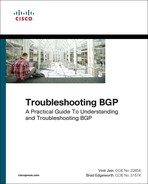
In Figure 1-5, R1, R2, and R3 are all within AS65100. R1 has an IBGP session with R2, and R2 has an IBGP session with R3. R1 advertises the 10.1.1.0/24 prefix to R2, which is processed and inserted into R2’s BGP table. R2 does not advertise the 10.1.1.0/24 NLRI to R3 because it received the prefix from an IBGP peer. To resolve this issue, R1 must form a multihop IBGP session so that R3 can receive the 10.1.1.0/24 prefix directly from R1. R1 connects to R3’s 10.1.23.3 IP address, and R3 connects to R1’s 10.1.12.1 IP address. R1 and R3 need a static route to the remote peering link, or R2 must advertise the 10.1.12.0/24 and 10.1.23.0/24 network into BGP.
Peering via Loopback Addresses
BGP sessions are sourced by the outbound interface toward the BGP peers IP address by default. Imagine three routers connected via a full mesh. In the event of a link failure on the R1-R3 link, R3’s BGP session with R1 times out and terminates. R3 loses connectivity to R1’s networks even though R1 and R3 could communicate through R2 (multihop path). The loss of connectivity occurs because IBGP does not advertise routes learned from another IBGP peer as in the previous section.
Two solutions exist to overcome the link failure:
![]() Add a second link between all routers (3 links will become 6 links) and establish two BGP sessions between each router.
Add a second link between all routers (3 links will become 6 links) and establish two BGP sessions between each router.
![]() Configure an IGP protocol on the routers’ transit links, advertise loopback interfaces into the IGP, and then configure the BGP neighbors to establish a session to the remote router’s loopback address.
Configure an IGP protocol on the routers’ transit links, advertise loopback interfaces into the IGP, and then configure the BGP neighbors to establish a session to the remote router’s loopback address.
Of the two methods, the second is more efficient and preferable.
The loopback interface is virtual and always stays up. In the event of link failure, the session remains intact while the IGP finds another path to the loopback address and, in essence, turns a single-hop IBGP session into a multihop IBGP session.
Updating the BGP configuration to set the destination of the BGP session to the remote router’s loopback IP address is not enough. The source IP address of the BGP packets will still reflect the IP address of the outbound interface. When a BGP packet is received, the router correlates the source IP address of the packet to the BGP neighbor table. If the BGP packet source does not match an entry in the neighbor table, the packet cannot be associated to a neighbor and is discarded.
The source of BGP packets can be set statically to an interface’s primary IP address with the BGP session configuration command neighbor ip-address update-source interface-type interface-number on IOS nodes. IOS XR and NX-OS devices use the command update-source interface-type interface-number under the neighbor session within the BGP router configuration.
Figure 1-6 illustrates the concept of peering using loopback addresses after the 10.1.13.0/24 network link fails. R1 and R3 still maintain BGP session connectivity while routes learned from OSPF allow BGP communication traffic between the loopbacks via R2. R1 can still forward packets to R3 via R2 because R1 performs a recursive lookup to identify R2 as the next-hop address.

Note
Sourcing BGP sessions from loopback interfaces eliminates the need to recompute the BGP best path algorithm if a peering link fails as shown in Figure 1-6. It also provides automatic load balancing if there are multiple equal cost paths via IGP to the loopback address.
EBGP
EBGP peerings are the core component of the BGP protocol on the Internet. EBGP is the exchange of network prefixes between autonomous systems. The following behaviors are different on EBGP sessions when compared to IBGP sessions:
![]() Time to Live (TTL) on BGP packets is set to one. BGP packets drop in transit if a multihop BGP session is attempted (TTL on IBGP packets is set to 255, which allows for multihop sessions).
Time to Live (TTL) on BGP packets is set to one. BGP packets drop in transit if a multihop BGP session is attempted (TTL on IBGP packets is set to 255, which allows for multihop sessions).
![]() The advertising router modifies the BGP next-hop to the IP address sourcing the BGP connection.
The advertising router modifies the BGP next-hop to the IP address sourcing the BGP connection.
![]() The advertising router prepends its ASN to the existing AS_PATH.
The advertising router prepends its ASN to the existing AS_PATH.
![]() The receiving router verifies that the AS_PATH does not contain an ASN that matches the local routers. BGP discards the NLRI if it fails the AS_PATH loop prevention check.
The receiving router verifies that the AS_PATH does not contain an ASN that matches the local routers. BGP discards the NLRI if it fails the AS_PATH loop prevention check.
The configuration for EBGP and IBGP sessions are fundamentally the same on IOS, IOS XR, and NX-OS devices, except that the ASN in the remote-as statement is different from the ASN defined in the BGP process.
Note
Different outbound (or inbound) route policies may be different from neighbor-to-neighbor, which allows for a dynamic routing-policy within an AS.
EBGP learned paths always have at least one ASN in the AS_PATH. If multiple ASs are listed in the AS_PATH, the most recent AS is always prepended (the furthest to the left). The BGP attributes for all paths to a specific network prefix can be shown with the command show bgp ipv4 unicast network on IOS, IOS XR, and NX-OS devices.
Example 1-8 displays the BGP path attributes for the remote prefix (192.168.3.3/32).
Example 1-8 BGP Prefix Attributes for Remote Prefix
R1-IOS# show bgp ipv4 unicast 192.168.3.3
BGP routing table entry for 192.168.3.3/32, version 11
Paths: (1 available, best #1, table default)
Not advertised to any peer
Refresh Epoch 1
65200 65300
10.1.12.2 from 10.1.12.2 (192.168.2.2)
Origin IGP, localpref 100, valid, external, best
Table 1-5 explains the output provided in Example 1-8 and its correlation to BGP. Some of the BGP path attributes may change depending on the BGP features used.


EBGP and IBGP Topologies
Combining EBGP sessions with IBGP sessions can cause confusion in terminology and concepts. Figure 1-6 provides a reference topology for clarification of concepts. R1 and R2 form an EBGP session, R3 and R4 form an EBGP session as well, and R2 and R3 form an IBGP session. R2 and R3 are IBGP peers and follow the rules of IBGP advertisement, even if the routes are learned from an EBGP peer.
As an EBGP prefix is advertised to an IBGP neighbor, issues may arise with the NLRI passing the validity check and the next-hop reachability check preventing advertisements to other BGP peers. The most common issue involves the failure of the next-hop accessibility. IBGP peers do not modify the next-hop address if the NLRI has a next-hop address other than 0.0.0.0. The next-hop address must be resolvable in the global RIB for it to be valid and advertised to other BGP peers.
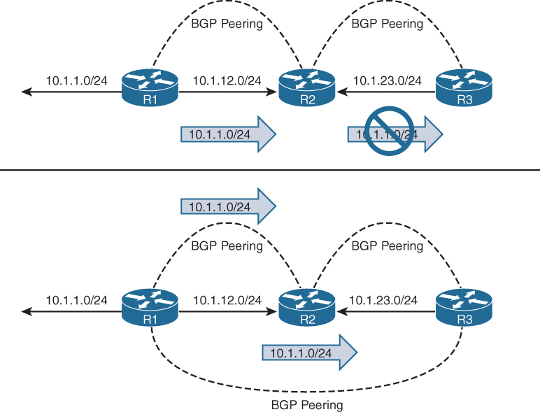
To demonstrate this concept, only R1 and R4 have advertised their loopback interfaces into BGP, 192.168.1.1/32, and 192.168.4.4/32. Figure 1-7, displays the BGP table for all four routers. Notice that the BGP best path symbol (>) is missing for the 192.168.4.4/32 prefix on R2, and for the 192.168.1.1/32 on R3.
R1’s BGP table is missing the 192.168.4.4/32 prefix because the prefix did not pass R2’s next-hop accessibility check preventing the execution of the BGP best path algorithm. R4 advertised the prefix to R3 with the next-hop address of 10.1.34.4, and R3 advertised the prefix to R2 with a next-hop address of 10.1.34.4. R2 does not have a route for the 10.1.34.4 IP address and deems the next-hop inaccessible. The same logic applies to R1’s 192.168.1.1/32 prefix when advertised toward R4.
Example 1-9 shows the BGP attributes on R3 for the 192.168.1.1/32 prefix. Notice that the prefix is not advertised to any peer because the next-hop is inaccessible.
Example 1-9 BGP Path Attributes for 192.168.1.1/32
R3-IOS# show bgp ipv4 unicast 192.168.1.1
BGP routing table entry for 192.168.1.1/32, version 2
Paths: (1 available, no best path)
Not advertised to any peer
Refresh Epoch 1
65100
10.1.12.1 (inaccessible) from 10.1.23.2 (192.168.2.2.2)
Origin IGP, metric 0, localpref 100, valid, internal
To correct the issue, the peering links, 10.1.12.0/24 and 10.1.34.0/24, need to be in both R2’s and R3’s routing table via either technique:
![]() IGP advertisement. Remember to use the passive interface to prevent an accidental adjacency from forming. Most IGPs do not provide the filtering capability like BGP.
IGP advertisement. Remember to use the passive interface to prevent an accidental adjacency from forming. Most IGPs do not provide the filtering capability like BGP.
![]() Advertising the networks into BGP.
Advertising the networks into BGP.
Both techniques allow the prefixes to pass the next-hop accessibility test.
Figure 1-8 displays the topology with both transit links advertised into BGP. Notice that this time all four prefixes are valid with a BGP best path selected.

Next-Hop Manipulation
Imagine a service provider network with 500 routers and every router containing 200 EBGP peering links. To ensure that the next-hop address is reachable to the IBGP peers requires the advertisement of 100,000 peering networks in BGP or an IGP consuming router resources.
Another technique to ensure that the next-hop address check passes without advertising peering networks into a routing protocol involves the modification of the next-hop address in the BGP advertisement. The next-hop IP address can be modified on inbound or outbound neighbor routing policies. Managing IP addresses in a route policy can be a complicated task. Configuring the next-hop-self address-family feature modifies the next-hop address in all external NLRIs using the IP address of the BGP neighbor.
The command neighbor ip-address next-hop-self [all] is used for each neighbor under the address-family configuration on IOS nodes, and the command next-hop-self is applied under the neighbor address-family configuration for IOS XR and NX-OS devices.
Figure 1-9 shows the topology and BGP routing table for all four routers. Notice that R2 and R3 advertised the EBGP routes to each other with the next-hop address as the BGP session IP address, allowing the NLRIs to pass the next-hop accessibility check.

Note
The next-hop-self feature does not modify the next-hop address for IBGP prefixes by default. IOS nodes can append the optional all keyword, which modifies the next-hop address on IBGP prefixes, too. IOS XR provides the BGP configuration command IBGP policy out enforce-modifications that will modify IBGP NLRIs in the same manner as EBGP NLRIs. NX-OS devices need to modify the next-hop address in a route-map to overcome this behavior for IBGP routes.
IBGP Scalability
The inability for BGP to advertise a prefix learned from one IBGP peer to another IBGP peer can lead to scalability issues within an AS. The formula n(n-1)/2 provides the number of sessions required where n represents the number of routers. A full mesh topology of 5 routers requires 10 sessions, and a topology of 10 routers requires 45 sessions. IBGP scalability becomes an issue for large networks.
Route Reflectors
RFC 1966 introduces the concept that an IBGP peering can be configured so that it reflects routes to another IBGP peer. The router reflecting routes is known as a route reflector (RR), and the router receiving reflected routes is a route reflector client. Three basic rules involve route reflectors and route reflection:
Rule #1: If a RR receives a NLRI from a non-RR client, the RR advertises the NLRI to a RR client. It does not advertise the NLRI to a non-route-reflector client.
Rule #2: If a RR receives a NLRI from a RR client, it advertises the NLRI to RR client(s) and non-RR client(s). Even the RR client that sent the advertisement receives a copy of the route, but it discards the NLRI because it sees itself as the route originator.
Rule #3: If a RR receives a route from an EBGP peer, it advertises the route to RR client(s) and non-RR client(s).
Figure 1-10 demonstrates the route reflector rules.

Only route reflectors are aware of this change in behavior because no additional BGP configuration is performed on route-reflector clients. BGP route reflection is specific to each address-family. The command neighbor ip-address route-reflector-client is used on IOS nodes, and the command route-reflector-client is used on IOS XR and NX-OS devices under the neighbor address-family configuration.
Loop Prevention in Route Reflectors
Removing the full mesh requirements in an IBGP topology introduces the potential for routing loops. When RFC 1966 was drafted, two other BGP route reflector specific attributes were added to prevent loops.
ORIGINATOR_ID, an optional nontransitive BGP attribute is created by the first route reflector and sets the value to the RID of the router that injected/advertised the route into the AS. If the ORIGINATOR_ID is already populated on an NLRI, it should not be overwritten.
If a router receives a NLRI with its RID in the Originator attribute, the NLRI is discarded.
CLUSTER_LIST, a nontransitive BGP attribute, is updated by the route reflector. This attribute is appended (not overwritten) by the route reflector with its cluster-id. By default this is the BGP identifier. The cluster-id can be set with the BGP configuration command bgp cluster-id cluster-id on IOS and IOS XR nodes. NX-OS devices use the command cluster-id cluster-id.
If a route reflector receives a NLRI with its cluster-id in the Cluster List attribute, the NLRI is discarded.
Example 1-10 provides sample output prefix output from a route that was reflected. Notice that the originator ID is the advertising router and that the cluster list contains two route-reflector IDs listed in the order of the last route reflector that advertised the route.
Example 1-10 Route Reflector Originator ID and Cluster List Attributes
RP/0/0/CPU0:R1-XR# show bgp ipv4 unicast 10.4.4.0/24
! Output omitted for brevity
Paths: (1 available, best #1)
Local
10.1.34.4 from 10.1.12.2 (192.168.4.4)
Origin IGP, metric 0, localpref 100, valid, internal, best, group-best
Received Path ID 0, Local Path ID 1, version 7
Originator: 192.168.4.4, Cluster list: 192.168.2.2, 192.168.3.3
Out-of-Band Route Reflectors
As explained earlier, BGP can establish multihop BGP sessions and does not change the next-hop path attribute when routes are advertised to IBGP neighbors. Some large network topologies use dedicated BGP routers for route reflection that are outside of the data path.
These out-of-band route reflectors provide control plane programming for the BGP routers that are in the data path and only require sufficient memory and processing power for the BGP routing table. Out-of-band route reflectors should not use the next-hop-self, or it will place the route reflector into the data path. Organizations that use MPLS L2VPNs, L3VPNs, and so on will use multiple out-of-band route reflectors for exchanging BGP path information.
Confederations
RFC 3065 introduced the concept of BGP confederations as an alternative solution to IBGP full mesh scalability issues shown earlier. A confederation consists of sub-ASs known as a Member-AS that combine into a larger AS known as an AS Confederation. Member ASs normally use ASNs from the private ASN range (64512-65535). EBGP peers from the confederation have no knowledge that they are peering with a confederation, and they reference the confederation identifier in their configuration.
Figure 1-11 demonstrates a BGP confederation with the confederation identifier of AS200. The Member-ASs are AS65100 and AS65200. R3 provides route reflection in Member-AS 65100.

Confederations share behaviors from both IBGP sessions and EBGP sessions. The changes are as follows:
![]() The AS_PATH attribute contains a subfield called AS_CONFED_SEQUENCE. The AS_CONFED_SEQUENCE is displayed in parentheses before any external ASNs in the AS_PATH. As the route passes from Member-AS to Member-AS, the AS_CONFED_SEQUENCE is appended to contain the Member-AS ASNs. The AS_CONFED_SEQUENCE attribute is used to prevent loops, but it is not used (counted) when choosing shortest AS_PATH.
The AS_PATH attribute contains a subfield called AS_CONFED_SEQUENCE. The AS_CONFED_SEQUENCE is displayed in parentheses before any external ASNs in the AS_PATH. As the route passes from Member-AS to Member-AS, the AS_CONFED_SEQUENCE is appended to contain the Member-AS ASNs. The AS_CONFED_SEQUENCE attribute is used to prevent loops, but it is not used (counted) when choosing shortest AS_PATH.
![]() Route reflectors can be used within the Member-AS like normal IBGP peerings.
Route reflectors can be used within the Member-AS like normal IBGP peerings.
![]() The BGP MED attribute is transitive to all other Member-ASs, but does not leave the confederation.
The BGP MED attribute is transitive to all other Member-ASs, but does not leave the confederation.
![]() The LOCAL_PREF attribute is transitive to all other Member-ASs, but does not leave the confederation.
The LOCAL_PREF attribute is transitive to all other Member-ASs, but does not leave the confederation.
![]() IOS XR nodes do not require a route policy when peering with a different Member-AS, even though the remote-as is different.
IOS XR nodes do not require a route policy when peering with a different Member-AS, even though the remote-as is different.
![]() The next-hop address for external confederation routes does not change as the route is exchanged between Member-AS to Member-AS.
The next-hop address for external confederation routes does not change as the route is exchanged between Member-AS to Member-AS.
![]() The AS_CONFED_SEQUENCE is removed from the AS_PATH when the route is advertised outside of the confederation.
The AS_CONFED_SEQUENCE is removed from the AS_PATH when the route is advertised outside of the confederation.
Configuring a BGP confederation is shown in the following steps:
Step 1. Create the BGP Routing Process. Initialize the BGP process with the global command router bgp member-asn.
Step 2. Set the BGP Confederation Identifier. Identify the BGP confederations with the command bgp confederation identifier as-number. The as-number is the BGP confederation ASN.
Step 3. Identify Peer Member-ASs. On routers that directly peer with another Member-AS, identify the peering Member-AS with the command bgp confederation peers member-asn.
Step 4. Configure BGP confederation members as normal; the remaining configuration follows normal BGP configuration guidelines.
Example 1-11 displays R1’s and R2’s BGP table. R1 resides in AS100 and does not see any of the BGP subconfederation information. R1 is not aware the AS200 is subdivided into a BGP confederation.
R2’s BGP table participates in the Member-AS 65100. Notice the next-hop address is not modified for the 10.67.1.0/24 (Network between R6 and R7) even though a Member-AS. The AS_CONFED_SEQUENCE is listed in parentheses to indicate it passed through Sub-AS 65200 in the AS200 confederation.
Example 1-11 R1’s and R2’s BGP Table
R1-IOS# show bgp ipv4 unicast
! Output omitted for brevity
Network Next Hop Metric LocPrf Weight Path
r> 10.1.12.0/24 10.1.12.2 0 0 200 i
*> 10.1.23.0/24 10.1.12.2 0 0 200 i
*> 10.1.25.0/24 10.1.12.2 0 0 200 i
*> 10.1.34.0/24 10.1.12.2 0 200 i
*> 10.1.46.0/24 10.1.12.2 0 200 i
*> 10.1.56.0/24 10.1.12.2 0 200 i
*> 10.1.67.0/24 10.1.12.2 0 200 i
R2-IOS# show bgp ipv4 unicast
! Output omitted for brevity
Network Next Hop Metric LocPrf Weight Path
*> 10.1.12.0/24 0.0.0.0 0 32768 i
* i 10.1.23.0/24 10.1.23.3 0 100 0 i
*> 0.0.0.0 0 32768 i
* 10.1.25.0/24 10.1.25.5 0 100 0 (65200) i
*> 0.0.0.0 0 32768 i
*>i 10.1.34.0/24 10.1.23.3 0 100 0 i
*>i 10.1.46.0/24 10.1.34.4 0 100 0 i
*> 10.1.56.0/24 10.1.25.5 0 100 0 (65200) i
* 10.1.67.0/24 10.1.56.6 0 100 0 (65200) i
*>i 10.1.46.6 0 100 0 (652000) i
Example 1-12 displays the NLRI information for 10.67.1.0/24 from the perspective of R2. Notice that the NLRI from within a confederation includes the option of confed-internal and confed-external for sources.
Example 1-12 Confederation NLRI
R2-IOS# show bgp ipv4 unicast 10.67.1.0/24
! Output omitted for brevity
BGP routing table entry for 10.1.67.0/24, version 8
Paths: (2 available, best #2, table default)
Advertised to update-groups:
1 3
Refresh Epoch 1
(65200)
10.56.1.6 from 10.1.25.5 (10.1.56.5)
Origin IGP, metric 0, localpref 100, valid, confed-external
rx pathid: 0, tx pathid: 0
Refresh Epoch 1
(65200)
10.46.1.6 from 10.1.23.3 (10.1.23.3)
Origin IGP, metric 0, localpref 100, valid, confed-internal, best
Originator: 10.1.34.4, Cluster list: 10.1.23.3
rx pathid: 0, tx pathid: 0x0
BGP Communities
BGP communities provide additional capability for tagging routes and for modifying BGP routing policy on upstream and downstream routers. BGP communities can be appended, removed, or modified selectively on each attribute as the route travels from router to router.
BGP communities are an optional transitive BGP attribute that can traverse from autonomous system to autonomous system. A BGP community is a 32-bit number that can be included with a route. A BGP community can be displayed as a full 32-bit number (0-4,294,967,295) or as two 16-bit numbers (0-65535):(0-65535) commonly referred to as new-format.
Private BGP communities follow the convention that the first 16-bits represent the AS of the community origination, and the second 16-bits represent a pattern defined by the originating AS. The private BGP community pattern could vary from organization to organization, do not need to be registered, and could signify geographic locations for one AS while signifying a method of route advertisement in another AS. Some organizations publish their private BGP community patterns on websites, such as http://www.onesc.net/communities/.
In 2006, RFC 4360 expanded BGP communities’ capabilities by providing an extended format. Extended BGP communities provide structure for various classes of information and are commonly used for VPN Services.
IOS XR and NX-OS devices display BGP communities in new-format by default, and IOS nodes display communities in decimal format by default. IOS nodes can display communities in new-format with the global configuration command ip bgp-community new-format.
Example 1-13 displays the BGP community in decimal format on top, and in new-format on bottom.
Example 1-13 BGP Community Formats
! DECIMAL FORMAT
R3# show bgp 192.168.1.1
! Output omitted for brevity
BGP routing table entry for 192.168.1.1/32, version 6
Community: 6553602 6577023
! New-Format
R3# show bgp 192.168.1.1
! Output omitted for brevity
BGP routing table entry for 192.168.1.1/32, version 6
Community: 100:2 100:23423
IOS and NX-OS devices do not advertise BGP communities to peers by default. Communities are enabled on a neighbor-by-neighbor basis with the BGP address-family configuration command neighbor ip-address send-community [standard | extended | both], and NX-OS devices use the command send-community [standard | extended | both] under the neighbor address-family configuration. Standard communities are sent by default, unless the optional extended or both keywords are used.
IOS XR advertises BGP communities to IBGP peers by default, but EBGP peers require the neighbor address-family configuration command send-community-ebgp for advertising standard BGP communities, and the command send-extended-community-ebgp to advertise extended BGP communities. Both commands are required if both community formats are to be sent to an EBGP peer.
Route Summarization
Summarizing prefixes conserves router resource(s) and accelerates best path calculation by reducing the size of the table. Summarization also provides the benefit(s) of stability by reducing routing churn by hiding route flaps from downstream routers. Although most ISPs do not accept prefixes larger than /24 for IPv4 (/25-/32), the Internet, at the time of this writing, still has more than 600,000 routes and continues to grow toward a million routes. Route summarization is required to reduce the size of the BGP table for Internet routers.
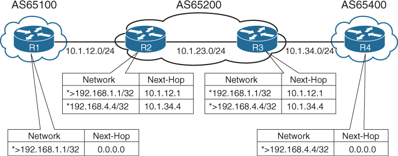
BGP route summarization on EBGP routers for nontransitive ASs reduce route computation on routers in the core of the nontransitive AS. In Figure 1-12, R3 summarizes all the EBGP routes received from AS65100 and AS65200 to reduce route computation on R4 during link flaps. In the event of a link flap on the 10.1.13.0/24 network, R3 removes all AS65100 routes learned directly from R1 and identifies the same networks via R2 with a different (longer AS_PATH). R4 processes the same changes that R3 processes and is a waste of CPU cycles because R4 receives connectivity only from R3. If R3 summarized the network range, instead of running the best-path algorithm against multiple routes, the best-path algorithm would execute only once.
The two techniques for BGP summarization are the following:
![]() Static: Create a static route to Null 0 for the prefix, and then advertise the network via a network statement. The downfall to this technique is that the summary route will always be advertised even if the networks are not available.
Static: Create a static route to Null 0 for the prefix, and then advertise the network via a network statement. The downfall to this technique is that the summary route will always be advertised even if the networks are not available.
![]() Dynamic: Configure an aggregation network range. When viable routes that match the network range enter the BGP table, an aggregate route is created. On the originating router, the aggregated prefix sets the next-hop to Null 0. The route to Null 0 is automatically created by BGP as a loop-prevention mechanism.
Dynamic: Configure an aggregation network range. When viable routes that match the network range enter the BGP table, an aggregate route is created. On the originating router, the aggregated prefix sets the next-hop to Null 0. The route to Null 0 is automatically created by BGP as a loop-prevention mechanism.
In both methods of route aggregation, a new network prefix with a shorter prefix length is advertised into BGP. Because the aggregated prefix is a new route, the summarizing router is the originator for the new aggregate route.
Aggregate-Address
Dynamic route summarization is accomplished with the BGP address-family configuration commands identified in Table 1-6.

The aggregate-address command advertises the aggregated route in addition to the original networks. Using the optional no-summary keyword suppresses the networks in the summarized network range. BGP considers aggregated addresses as local routes.
Note
Aggregate addresses are local BGP routes when modifying BGP AD.
Flexible Route Suppression
Some traffic engineering designs require “leaking” routes, which is the advertisement of a subset of more specific routes in addition to performing the summary. Leaking routes can be done at the process by explicitly stating the prefixes to suppress, or on a neighbor level by indicating which prefixes should not be suppressed.
Selective Prefix Suppression
Selective prefix suppression explicitly lists the networks that should not be advertised along with the summary route to neighbor routers.
IOS and NX-OS uses a suppress-map, which uses the keyword suppress-map route-map-name instead of using the no-summary keyword. In the referenced route-map, only the prefixes that should be suppressed are permitted. IOS XR routers use the keyword route-policy route-policy-name in lieu of the no-summary keyword. In the route policy, the action command suppress is used after conditionally matching the prefixes that should be suppressed.
Leaking Suppressed Routes
The summary-only keyword suppresses all the more specific routes of an aggregate address from being advertised. After a route is suppressed, it is still possible to advertise the suppressed route to a specific neighbor.
IOS devices use an unsuppress-map with the BGP neighbor address-family configuration command neighbor ip-address unsuppress-map route-map-name. In the referenced route-map, only the prefixes that should be leaked are permitted. IOS XR routers use an outbound route policy with the action command unsuppress to indicate which prefixes should be leaked.
Atomic Aggregate
Aggregated routes act like new BGP routes with a shorter prefix length. When a BGP router summarizes a route, it does not advertise the AS path information from before the aggregation. BGP path attributes such as AS-Path, MED, and BGP communities are not included in the new BGP advertisement. The Atomic Aggregate attribute indicates that a loss of path information has occurred.
![]() R1 and R2 are advertising the 172.16.1.0/24 and 172.16.2.0/24 networks.
R1 and R2 are advertising the 172.16.1.0/24 and 172.16.2.0/24 networks.
![]() R3 is aggregating the routes into the 172.16.0.0/22 network range, which is advertised to all of R3’s peers
R3 is aggregating the routes into the 172.16.0.0/22 network range, which is advertised to all of R3’s peers
Example 1-14 displays R3’s BGP table. R1’s BGP prefix 172.16.1.0/24 advertised to R3. Notice the AS-Path of 65100 and BGP Community of 100:100.
Example 1-14 172.16.1.0/24 BGP Path Information
R3-IOS# show bgp ipv4 unicast 172.16.1.0
BGP routing table entry for 172.16.1.0/24, version 13
Paths: (1 available, best #1, table default, Advertisements suppressed by an aggre-
gate.)
Not advertised to any peer
Refresh Epoch 1
65100
10.1.13.1 from 10.1.13.1 (192.168.1.1)
Origin IGP, metric 0, localpref 100, valid, external, best
Community: 100:100
R3’s aggregate route (summary) does not include the BGP communities (including AS-Path history) for the routes in the summarization range. R3 advertises the aggregate route to R1 and R2, and those routers install the 172.16.0.0/22 summary route because their AS-Path is not listed in the AS-Path attribute and passes the AS-Path loop check.
Example 1-15 displays the BGP path information for the 172.16.0.0/22 summary network on R1. The AS-Path of the aggregated route displays only the aggregating router, but does not include the AS-Path of the routes being summarized (AS65100 or AS65200), nor is the BGP community included in the routes being summarized. The BGP path information indicates that this is an aggregated prefix and was aggregated by R3 (192.168.3.3). The Atomic-Aggregate in the route indicates a loss of information occurred during aggregation on the aggregating router.
Example 1-15 172.16.0.0/22 BGP Path Information
R1-IOS# show bgp ipv4 unicast 172.16.0.0
BGP routing table entry for 172.16.0.0/21, version 5
Paths: (1 available, best #1, table default)
Not advertised to any peer
Refresh Epoch 1
300, (aggregated by 300 192.168.3.3)
10.1.13.3 from 10.1.13.3 (192.168.3.3)
Origin IGP, metric 0, localpref 100, valid, external, atomic-aggregate, best
Route Aggregation with AS_SET
To keep the BGP path information history, the optional as-set keyword may be used with the aggregate-address command. As the router generates the aggregate route, BGP attributes from the summarized routes are copied over to it. The AS-Path settings from the original prefixes are stored in the AS_SET portion of the AS-Path. (The AS_SET is displayed within brackets, and counts only as one hop, even if multiple ASs are listed.)
Route Aggregation with Selective Advertisement of AS-SET
Using the AS-SET feature with network aggregation combines all the attributes of the original prefixes into the aggregated prefixes. This might cause issues with your routing policy. For example, if one of the prefixes contains the No-Export BGP community, the aggregate address will not be exported. To resolve these types of problems, selectively choose the routes that the path attributes will copy to the aggregate route. The use of the advertise-map option allows for conditionally matching and denying attributes that should be permitted or denied in the aggregated route.
Default Route Advertisement
Advertising a default route into the BGP table requires the default route to exist in the RIB and the BGP configuration command default-information originate to be used. The redistribution of a default route or use of a network 0.0.0.0/0 does not work without the default-information originate command.
Default Route Advertisement per Neighbor
Some network topologies restrict the size of the BGP advertisements to a neighbor because the remote router does not have enough processing power or memory for the full BGP routing table. Connectivity is still required, so the peering routers only advertise the default route to the remote router.
A default route is advertised to a BGP peer with the BGP address-family configuration command neighbor ip-address default-originate for IOS nodes or with the BGP neighbor address-family configuration command default-originate for IOS XR and NX-OS devices. Default route advertisement to a specific neighbor does not require a default route to be present in the RIB or BGP Loc-RIB table.
Note
A behavior difference between IOS and IOS XR occurs when a default route is already present in the BGP table. IOS nodes advertise the route as if it was the originating router. (None of the existing attributes are passed to the peer.) IOS XR nodes advertise the network to the peer as it exists in the BGP table with the entire default route attributes (AS-Path, and so on).
Remove Private AS
Some organizations might not be able to meet the qualifications for obtaining their own ASN but still want to receive Internet routing tables from their service provider. In these situations, the service provider may assign the organization a private ASN for peering. Private ASNs should not be advertised by the service provider to other ISPs on the Internet.
The feature remove private AS removes the private AS of routes that are advertised to the configured peer. The router performs the following path analysis with the remove private AS feature:
![]() Removes only private ASNs on routes advertised to EBGP peers.
Removes only private ASNs on routes advertised to EBGP peers.
![]() If the AS-Path for the route has only private ASNs, the private ASNs are removed.
If the AS-Path for the route has only private ASNs, the private ASNs are removed.
![]() If the AS-Path for the route has a private ASN between public ASNs, it is assumed that this is a design choice, and the private ASN is not removed
If the AS-Path for the route has a private ASN between public ASNs, it is assumed that this is a design choice, and the private ASN is not removed
![]() If the AS-Path contains confederations (AS_CONFED_SEQ), BGP removes the private AS numbers only if they are included after the AS_CONFED_SEQ (Confederation AS-Path) of the path.
If the AS-Path contains confederations (AS_CONFED_SEQ), BGP removes the private AS numbers only if they are included after the AS_CONFED_SEQ (Confederation AS-Path) of the path.
The remove private AS feature is configured on IOS nodes with the BGP address-family configuration command neighbor ip-address remove-private-as. IOS XR and NX-OS devices use the BGP neighbor address-family configuration command remove-private-as.
Allow AS
The Allow AS feature allows for routes to be received and processed even if the router detects its own ASN in the AS-Path. A router discards BGP network prefixes if it sees its ASN in the AS-Path as a loop prevention mechanism. Some network designs use a transit AS to provide connectivity to two different locations. BGP detects the network advertisements from the remote site as a loop and discards the route. The AS-Path loop check feature needs to be disabled to maintain connectivity in scenarios such as these.
On IOS nodes, the command neighbor ip-address allowas-in is placed under the address-family. IOS XR and NX-OS nodes use the BGP neighbor address-family configuration command allowas-in.
LocalAS
When two companies merge, one of the ASNs is usually returned to the regional Internet registry (RIR). During the migration, each company needs to maintain its own ASN while changes are made with its peering neighbors to update their configuration.
The LocalAS feature is configured on a per peer basis, and allows for BGP sessions to establish using an alternate ASN than the ASN that the BGP process is running on. The LocalAS feature works only with EBGP peerings.
IOS nodes use the BGP address-family neighbor configuration command neighbor ip-address local-as alternate-as-number [no-prepend [replace-as [dual-as]]]. IOS XR and NX-OS devices use the equivalent command local-as alternate-as-number [no-prepend [replace-as [dual-as]]] under the neighbor. By default, the alternate ASN is added to the AS-Path for routes that are sent and received between these two peers.
One problem with the alternate ASN being prepended when receiving the routes is that other IBGP peers drop the network prefixes as part of a routing loop detection.
![]() To stop the alternate ASN from being prepended when receiving routes, the optional keyword no-prepend is used.
To stop the alternate ASN from being prepended when receiving routes, the optional keyword no-prepend is used.
![]() To stop the alternate ASN from being prepended when sending routes, the optional keywords no-prepend replace-as is used.
To stop the alternate ASN from being prepended when sending routes, the optional keywords no-prepend replace-as is used.
![]() If both no-prepend replace-as keywords are used, all routers see the BGP advertisements as if they were running the original AS in the BGP process.
If both no-prepend replace-as keywords are used, all routers see the BGP advertisements as if they were running the original AS in the BGP process.
After the remote peer changes the remote-as setting on the BGP configuration, the local-as commands should be removed. If the coordination of maintenance windows cannot occur during the same time, the no-prepend replace-as dual-as optional keywords allow the remote peer to user either ASN for the BGP session. The remote BGP router peers with the ASN in the router process statement, or the alternate ASN in the local-as configuration.
Summary
BGP is a powerful path vector routing protocol that provides scalability and flexibility that cannot be compared to any other routing protocol. BGP uses TCP port 179 for all BGP communication between peers, which allows BGP to establish sessions with directly attached routers or with routers that are multiple hops away.
Originally, BGP was intended for the routing of IPv4 prefixes between organizations, but over the years has had significant increase in functionality and feature enhancements. BGP has expanded from being an Internet routing protocol to other aspects of the network, including the data center.
BGP provides a scalable control-plane signaling for overlay topologies, including MPLS VPNs, IPsec SAs, and VXLAN. These overlays can provide Layer 3 services, such as L3VPNs, or Layer 2 services, such as eVPNs, across a widely used scalable control plane for everything from provider-based services to data center overlays. Every AFI / SAFI combination maintains an independent BGP table and routing policy, which makes BGP the perfect control plane application.
This chapter provided a fundamental overview of BGP from a session perspective, as well as route advertisement behaviors for IPv4 and IPv6 protocols. Networking vendors continue to use BGP for new features, and having the ability to effectively troubleshoot BGP is becoming more and more necessary.
This book provides emphasis on various BGP-related problems that are encountered in real-life deployments, which have caused major outages to the network over the years.
References
RFC 1654: A Border Gateway Protocol 4 (BGP-4), Y. Rekhter, T. Li, http://tools.ietf.org/html/rfc1654, July 1994.
RFC 1966: BGP Route Reflection, An alternative to full mesh IBGP, T. Bates, R. Chandra, http://www.ietf.org/rfc/rfc1966.txt, June 1996.
RFC 3065: Autonomous System Confederations for BGP, P. Traina et al., http://www.ietf.org/rfc/rfc3065.txt, February 2001.
RFC 4271: A Border Gateway Protocol 4 (BGP-4), Y. Rekhter et al., http://www.ietf.org/rfc/rfc4271.txt, January 2006.
RFC 4360: BGP Extended Communities Attribute, Srihari Sangli, Dan Tappan, Yakov Rekhter, IETF, http://www.ietf.org/rfc/rfc4360.txt, February 2006.
RFC 4451: BGP MULTI_EXIST_DISC (MED) Considerations, D. McPherson, V. Gill, http://www.ietf.org/rfc/rfc4451.txt, March 2006.
RFC 4893: BGP Support for Four-octet AS Number Space, Q. Vohra, E. Chen, http://www.ietf.org/rfc/rfc4893.txt, May 2007.
Edgeworth, Brad, Foss, Aaron, Garz Rios, Ramiro. IP Routing on Cisco IOS, IOS XE, and IOS XR. Indianapolis: Cisco Press: 2014.
Cisco. Cisco IOS Software Configuration Guides. http://www.cisco.com
Cisco. Cisco IOS XR Software Configuration Guides. http://www.cisco.com
Cisco. Cisco NX-OS Software Configuration Guides. http://www.cisco.com