Chapter 1
Introduction to Nexus Operating System (NX-OS)
This chapter covers the following topics:
At the time of its release in 2008, the Nexus operating system (NX-OS) and the Nexus 7000 platform provided a substantial leap forward in terms of resiliency, extensibility, virtualization, and system architecture compared to other switching products of the time. Wasteful excess capacity in bare metal server resources had already given way to the efficiency of virtual machines and now that wave was beginning to wash over to the network as well. Networks were evolving from traditional 3-Tier designs (access layer, distribution layer, core layer) to designs that required additional capacity, scale, and availability. It was no longer acceptable to have links sitting idle due to Spanning Tree Protocol blocking while that capacity could be utilized to increase the availability of the network.
As network topologies evolved, so did the market’s expectation of the network infrastructure devices that connected their hosts and network segments. Network operators were looking for platforms that were more resilient to failures, offered increased switching capacity, and allowed for additional network virtualization in their designs to better utilize physical hardware resources. Better efficiency was also needed in terms of reduced power consumption and cooling requirements as data centers grew larger with increased scale.
The Nexus 7000 series was the first platform in Cisco’s Nexus line of switches created to meet the needs of this changing data center market. NX-OS combines the functionality of Layer 2 switching, Layer 3 routing, and SAN switching into a single operating system. From the initial release, the operating system has continued to evolve, and the portfolio of Nexus switching products has expanded to include several series of switches that address the needs of a modern network. Throughout this expansion, the following four fundamental pillars of NX-OS have remained unchanged:
Resiliency
Virtualization
Efficiency
Extensibility
This chapter introduces the different types of Nexus platforms along with their placement into the modern network architecture, and the major functional components of NX-OS. In addition, some of the advanced serviceability and usability enhancements are introduced to prepare you for the troubleshooting chapters that follow. This enables you to dive into each of the troubleshooting chapters with a firm understanding of NX-OS and Nexus switching to build upon.
Nexus Platforms Overview
The Cisco Nexus switching portfolio contains the following platforms:
Nexus 2000 Series
Nexus 3000 Series
Nexus 5000 Series
Nexus 6000 Series
Nexus 7000 Series
Nexus 9000 Series
The following sections introduce each Nexus platform and provide a high-level overview of their features and placement depending on common deployment scenarios.
Nexus 2000 Series
The Nexus 2000 series is a group of devices known as a fabric extender (FEX). FEXs essentially act as a remote line card for the parent switch extending its fabric into the server access layer.
The FEX architecture provides the following benefits:
Extend the fabric to hosts without the need for spanning tree
Highly scalable architecture that is common regardless of host type
Single point of management from the parent switch
Ability to upgrade parent switch and retain the FEX hardware
The Nexus 2000 FEX products do not function as standalone devices; they require a parent switch to function as a modular system. Several models are available to meet the host port physical connectivity requirements with various options for 1 GE, 10 GE connectivity as well as Fiber Channel over Ethernet (FCoE). On the fabric side of the FEX, which connects back to the parent switch, different options exist for 1 GE, 10 GE, and 40 GE interfaces. The current FEX Models are as follows:
1 GE Fabric Extender Models: (2224TP, 2248TP, 2248TP-E)
10 GBase-T Fabric Extender Models: (2332TQ, 2348TQ, 2348TQ-E, 2232TM-E, 2232TM)
10 G SFP+ Fabric Extender Models: (2348UPQ, 2248PQ, 2232PP)
When deciding on a FEX platform, consider the host connectivity requirements, the parent switch connectivity requirements, and compatibility of the parent switch model. The expected throughput and performance of the hosts should also be a consideration because the addition of a FEX allows oversubscription of the fabric-side interfaces based on the front panel bandwidth available for hosts.
Nexus 3000 Series
The Nexus 3000 series consists of several models of high performance, low-latency, fixed configuration switches. They offer a compact 1 or 2 RU (rack unit) footprint with a high density of front panel ports ranging in speed from 1 GE, 10 GE, 40 GE, to 100GE. These switches are not only high performance but also versatile because they support a wide range of Layer 2 features as well as support for Layer 3 routing protocols and IP Multicast. The model number is a combination of the platform series, the number of ports or the total bandwidth of the ports, and the type of interfaces.
The current Nexus 3000 models are as follows:
Nexus 3000 Models: (3064X, 3064-32T, 3064T, 3048)
Nexus 3100 Models: (3132Q/3132Q-X, 3164Q, 3172PQ, 3172TQ, 31128PQ)
Nexus 3100V Models: (31108PC-V, 31108TC-V, 3132Q-V)
Nexus 3200 Models: (3232C, 3264Q)
Nexus 3500 Models: (3524/3524-X, 3548/3548-X)
Nexus 3600 Models: (36180YC-R)
Each of these models has advantages depending on the intended role. For example, the Nexus 3500 series are capable of ultra-low-latency switching (sub-250ns), which makes them popular for high-performance computing as well as high-frequency stock trading environments. The 3100-V is capable of Virtual Extensible Local Area Network (VXLAN) routing, the 3200 offers low-latency and larger buffers, while the 3000 and 3100 series are good all-around line rate Top of Rack (ToR) switches.
Note
All Nexus 3000 series, with the exception of the Nexus 3500 series, run the same NX-OS software release as the Nexus 9000 series switches.
Nexus 5000 Series
The Nexus 5000 series support a wide range of Layer 2 and Layer 3 features, which allows versatility depending on the network design requirements. The Nexus 5500 series require the installation of additional hardware and software licensing for full Layer 3 support, whereas the Nexus 5600 series offers a native Layer 3 routing engine capable of 160 Gbps performance. The Nexus 5600 also supports VXLAN and larger table sizes compared to the 5500 series.
The current Nexus 5000 models are as follows:
Nexus 5500 Models: (5548UP, 5596UP, 5596T)
Nexus 5600 Models: (5672UP, 5672UP-16G, 56128P, 5624Q, 5648Q, 5696Q)
The Nexus 5000 series is well suited as a Top of Rack (ToR) or End of Row (EoR) switch for high-density and high-scale environments. They support 1 GE, 10 GE, and 40 GE connectivity for Ethernet and FCoE. Superior port densities are achieved when used as a parent switch for FEX aggregation. The 5696Q supports 100 GE uplinks with the addition of expansion modules. The platform naming convention is the model family, then the supported number of ports at 10 GE or 40 GE depending on the model. A Nexus 5672 is a 5600 platform that supports 72 ports of 10 GE Ethernet, and the UP characters indicate the presence of 40 GE uplink ports.
The support for Layer 3 features combined with a large number of ports, FEX aggregation, and the flexibility of supporting Ethernet, FCoE, and Fibre Channel in a single platform make the Nexus 5000 series a very attractive ToR or EoR option for many environments.
Nexus 6000 Series
The Nexus 6001 and Nexus 6004 switches are suited for ToR and EoR placement in high-density data center networks. The 6001 is a 1RU chassis that supports connectivity to 1 GE to 10 GE servers, and the 6004 is a 4RU chassis suited for 10 GE to 40 GE server connectivity or FCoE. FEX aggregation is also a popular application of the Nexus 6000 series. The Nexus 6000 series offers large buffers and low latency switching to meet the needs of high-performance computing environments. They support robust Layer 2, Layer 3, and storage feature sets with the appropriate feature license installed. The Nexus 6000 series has reached end of sale in its product life cycle as of April 30, 2017. The Nexus 5600 platform is designated as the replacement platform because it offers similar benefits, density, and placement in the data center.
Nexus 7000 Series
The Nexus 7000 series first shipped nearly 10 years ago, and it continues to be a very popular option for enterprise, data center, and service provider networks around the world. There are many reasons for its success. It is a truly modular platform based on a fully distributed crossbar fabric architecture that provides a large number of features. The Nexus 7000 series is categorized into two chassis families: the 7000 and the 7700. The 7000 series chassis are available in the following configurations, where the last two digits of the platform name represent the number of slots in the chassis:
Nexus 7000 Models: (7004, 7009, 7010, 7018)
Nexus 7700 Models: (7702, 7706, 7710, 7718)
The different chassis configurations allow for optimal sizing in any environment. The 7000 series has five fabric module slots, whereas the 7700 has six fabric module slots. The 7004 and the 7702 do not use separate fabric modules because the crossbar fabric on the Input/Output (I/O) modules are sufficient for handling the platform’s requirements. Access to the fabric is controlled by a central arbiter on the supervisor. This grants access to the fabric for ingress modules to send packets toward egress modules. Virtual output queues (VOQ) are implemented on the ingress I/O modules that represent the fabric capacity of the egress I/O module. These VOQs minimize head-of-line blocking that could occur waiting for an egress card to accept packets during congestion.
The Nexus 7000 and 7700 utilize a supervisor module that is responsible for running the management and control plane of the platform as well as overseeing the platform health. The supervisor modules have increased in CPU power, memory capacity, and switching performance, with each generation starting with the Supervisor 1, then the Supervisor 2, and then the current Supervisor 2E.
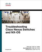
Because the Nexus 7000 is a distributed system, the I/O modules run their own software, and they are responsible for handling all the data plane traffic. All Nexus 7000 I/O modules fall into one of two families of forwarding engines: M Series or F Series. Both families of line cards have port configurations that range in speed from 1 GE, 10 GE, 40 GE, to 100 GE. They are commonly referred to by their forwarding engine generation (M1, M2, M3 and F1, F2, and F3), with each generation offering improvements in forwarding capacity and features over the previous. The M series generally has larger forwarding table capacity and larger packet buffers. Previously the M series also supported more Layer 3 features than the F series, but with the release of the F3 cards, the feature gap has closed with support for features like Locator-ID Separation Protocol (LISP) and MPLS. Figure 1-1 explains the I/O module naming convention for the Nexus 7000 series.
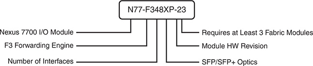
Figure 1-1 Nexus 7000 Series I/O Module Naming Convention
The Nexus 7000 is typically deployed in an aggregation or core role; however, using FEXs with the Nexus 7000 provides high-density access connectivity for hosts. The Nexus 7000 is also a popular choice for overlay technologies like MPLS, LISP, Overlay Transport Virtualization (OTV), and VXLAN due to its wide range of feature availability and performance.
Nexus 9000 Series
The Nexus 9000 Series was added to the lineup in late 2013. The Nexus 9500 is a modular switch and was the first model to ship with several innovative features. The modular chassis was designed to minimize the number of components so it does not have a mid-plane. The line-card modules interface directly to the fabric modules in the rear of the chassis. The switching capacity of the chassis is determined by adding up to six fabric modules that are designed to be full line rate, nonblocking to all ports. Recently the R-Series line cards and fabric modules were released, which feature deep buffer capabilities and increased forwarding table sizes for demanding environments. The Nexus 9500 is a modular switching platform and therefore has supervisor modules, fabric modules, and various line-card options. Two supervisor modules exist for the Nexus 9500:
Supervisor A with a 4 core 1.8 GHz CPU, 16 GB of RAM, and 64 GB of SSD storage
Supervisor B with a 6 core 2.2 GHz CPU, 24 GB of RAM, and 256 GB of SSD storage
The Nexus 9000 series uses a mix of commodity merchant switching application- specific integrated circuits (ASIC) as well as Cisco’s developed ASICs to reduce cost where appropriate. The Nexus 9500 was followed by the Nexus 9300 and Nexus 9200 series. Interface speeds of 1 GE, 10 GE, 25 GE, 40 GE, and 100 GE are possible, depending on the model, and FCoE and FEX aggregation is also supported on select models. The 9500 is flexible and modular, and it could serve as a leaf/aggregation or core/spine layer switch, depending on the size of the environment.
The 9300 and 9200 function well as high-performance ToR/EoR/leaf switches. The Nexus 9000 series varies in size from 1RU to 21RU with various module and connectivity options that match nearly any connectivity and performance requirements. The available models are as follows:
Nexus 9500 Models: (9504, 9508, 9516)
Nexus 9300 100M/1G Base-T Models: (9348GC-FXP)
Nexus 9300 10 GBaseT Models: (9372TX, 9396TX, 93108TC-FX, 93120TX, 93128TX, 93108TC-EX)
Nexus 9300 10/25 GE Fiber Models: (9372PX, 9396PX, 93180YC-FX, 93180YC-EX)
Nexus 9300 40 GE Models: (9332PQ, 9336PQ, 9364C, 93180LC-EX)
Nexus 9200 Models: (92160YC-X, 9272Q, 92304QC, 9236C, 92300YC)
The Nexus 9000 platform naming convention is explained in Figure 1-2.
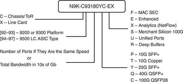
Figure 1-2 Nexus 9000 Series Naming Convention
The Nexus 9000 series is popular in a variety of network deployments because of its speed, broad feature sets, and versatility. The series is used in high-frequency trading, high-performance computing, large-scale leaf/spine architectures, and it is the most popular Cisco Nexus platform for VXLAN implementations.
Note
The Nexus 9000 series operates in standalone NX-OS mode or in application-centric infrastructure (ACI) mode, depending on what software and license is installed. This book covers only Nexus standalone configurations and troubleshooting.
The portfolio of Nexus switching products is always evolving. Check the product data sheets and documentation available on www.cisco.com for the latest information about each product.
NX-OS Architecture
Since its inception, the four fundamental pillars of NX-OS have been resiliency, virtualization, efficiency, and extensibility. The designers also wanted to provide a user interface that had an IOS-like look and feel so that customers migrating to NX-OS from legacy products feel comfortable deploying and operating them. The greatest improvements to the core operating system over IOS were in the following areas:
Process scheduling
Memory management
Process isolation
Management of feature processes
In NX-OS, feature processes are not started until they are configured by the user. This saves system resources and allows for greater scalability and efficiency. The features use their own memory and system resources, which adds stability to the operating system. Although similar in look and feel, under the hood, the NX-OS operating system has improved in many areas over Cisco’s IOS operating system.
The NX-OS modular architecture is depicted in Figure 1-3.
Figure 1-3 NX-OS Modular Architecture
Note
The next section covers some of the fundamental NX-OS components that are of the most interest. Additional NX-OS services and components are explained in the context of specific examples throughout the remainder of this book.
The Kernel
The primary responsibility of the kernel is to manage the resources of the system and interface with the system hardware components. The NX-OS operating system uses a Linux kernel to provide key benefits, such as support for symmetric-multiprocessors (SMPs) and pre-emptive multitasking. Multithreaded processes can be scheduled and distributed across multiple processors for improved scalability. Each component process of the OS was designed to be modular, self-contained, and memory protected from other component processes. This approach results in a highly resilient system where process faults are isolated and therefore easier to recover from when failure occurs. This self-contained, self-healing approach means that recovery from such a condition is possible with no or minimal interruption because individual processes are restarted and the system self-heals without requiring a reload.
Note
Historically, access to the Linux portion of NX-OS required the installation of a “debug plugin” by Cisco support personnel. However, on some platforms NX-OS now offers a feature bash-shell that allows users to access the underlying Linux portion of NX-OS.
System Manager (sysmgr)
The system manager is the NX-OS component that is responsible for the processes running on the system. That means that the system manager starts the processes and then monitors their health to ensure they are always functional. If a process fails, the system manager takes action to recover. Depending on the nature of the process, this action could be restarting the process in a stateful or stateless manner, or even initiating a system switchover (failover to the redundant supervisor) to recover the system if needed.
Processes in NX-OS are identified by a Universally Unique Identifier (UUID), which is used to identify the NX-OS service it represents. The UUID is used by NX-OS because a process ID (PID) may change, but the UUID remains consistent even if the PID changes.
The command show system internal sysmgr service all displays all the services, their UUID, and PID as shown in Example 1-1. Notice that the Netstack service has a PID of 6427 and a UUID of 0x00000221.
Example 1-1 show system internal sysmgr service all Command
count
---------------- ---------- ------ ----- --------- ------ --- ----- ---
aaa 0x000000B5 6227 111 s0009 1 N/A 0
ospf 0x41000119 13198 320 s0009 2 32 1
psshelper_gsvc 0x0000021A 6147 398 s0009 1 N/A 0
platform 0x00000018 5817 39 s0009 1 N/A 0
radius 0x000000B7 6455 113 s0009 1 N/A 0
securityd 0x0000002A 6225 55 s0009 1 N/A 0
tacacs 0x000000B6 6509 112 s0009 1 N/A 0
eigrp 0x41000130 [NA] [NA] s0075 1 N/A 1
mpls 0x00000115 6936 274 s0009 1 N/A 1
mpls_oam 0x000002EF 6935 226 s0009 1 N/A 1
mpls_te 0x00000120 6934 289 s0009 1 N/A 1
mrib 0x00000113 6825 255 s0009 1 N/A 1
netstack 0x00000221 6427 262 s0009 1 N/A 0
nfm 0x00000195 6824 306 s0009 1 N/A 1
ntp 0x00000047 6462 72 s0009 1 N/A 0
obfl 0x0000012A 6228 1018 s0009 1 N/A 0
Additional details about a service, such as its current state, how many times it has restarted, and how many times it has crashed is viewed by using the UUID obtained in the output of the previous command. The syntax for the command is show system internal sysmgr service uuid uuid as demonstrated in Example 1-2.
Example 1-2 show system internal sysmgr service Command
UUID = 0x221.
Service "netstack" ("netstack", 182):
UUID = 0x221, PID = 6427, SAP = 262
State: SRV_STATE_HANDSHAKED (entered at time Fri Feb 17 23:56:39 2017).
Restart count: 1
Time of last restart: Fri Feb 17 23:56:39 2017.
The service never crashed since the last reboot.
Tag = N/A
Plugin ID: 0
Note
If a service has crashed, the process name, PID, and date/time of the event is found in the output of show cores.
For NX-OS platforms with redundant supervisor modules, another important role of the system manager is to coordinate state between services on the active and standby supervisors. The system manager ensures synchronization in the event the active fails and the standby needs to take over.
Messages and Transactional Services
The modular and self-contained nature of NX-OS services necessitates that processes have a way for messages and data to be exchanged between processes while maintaining the self-contained architecture mentioned previously. The operating system component responsible for this service-to-service communication is the Messages and Transactional Services (MTS).
As the name implies, MTS is used for interprocess communication in NX-OS. This is facilitated using service access points (SAP) to allow services to exchange messages. To use an analogy, if the MTS is the postal service, think of the SAP as a post office box for a process. Messages are sent and received by a process using its SAP over MTS.
The system manager table output referenced previously is used again to reference a service name and find its UUID, PID, and the SAP. This SAP number is then used to get details from MTS on the number of messages exchanged and what the state of the MTS buffers are for this service. To illustrate this, an OSPF process is configured with a process tag of 32. Example 1-3 shows the OSPF process in the output of show system internal sysmgr service all. This output is used to locate the UUID 0x41000119, the PID of 13198, and the SAP of 320.
Example 1-3 Locate the UUID for a Service Name
---------------- ---------- ------ ----- --------- ------ --- ----- ---
aaa 0x000000B5 6227 111 s0009 1 N/A 0
platform 0x00000018 5817 39 s0009 1 N/A 0
In Example 1-4, the show system internal mts sup sap sap-id [description | uuid | stats] command is used to obtain details about a particular SAP. To examine a particular SAP, first confirm that the service name and UUID match the values from the show system internal sysmgr services all command. This is a sanity check to ensure the correct SAP is being investigated. The output of show system internal mts sup sap sap-id [description] should match the service name, and the output of show system internal mts sup sap sap-id [UUID] should match the UUID in the sysmgr output. Next examine the MTS statistics for the SAP. This output is useful to determine what the maximum value of the MTS queue was (high-water mark), as well as examining the number of messages this service has exchanged. If the max_q_size ever reached is equal to the hard_q_limit it is possible that MTS has dropped messages for that service.
Example 1-4 Examining the MTS Queue for a SAP
Below shows sap on default-VDC, to show saps on non-default VDC, run
show system internal mts node sup-<vnode-id> sap ...
Below shows sap on default-VDC, to show saps on non-default VDC, run
show system internal mts node sup-<vnode-id> sap ...
Below shows sap on default-VDC, to show saps on non-default VDC, run
show system internal mts node sup-<vnode-id> sap ...
msg tx: 40
byte tx: 6829
msg rx: 20
byte rx: 2910
opc sent to myself: 32768
max_q_size q_len limit (soft q limit): 1024
max_q_size q_bytes limit (soft q limit): 50%
max_q_size ever reached: 13
max_fast_q_size (hard q limit): 4096
rebind count: 0
Waiting for response: none
buf in transit: 40
bytes in transit: 6829
NX-1# hex 1090519321
0x41000119
NX-1# dec 0x41000119
1090519321
Note
In the output of Example 1-4, the UUID is displayed as a decimal value, whereas in the output from the system manager it is given as hexadecimal. NX-OS has a built-in utility to do the conversion using the hex value or dec value command.
The NX-OS MTS service is covered in more detail in Chapter 3, “Troubleshooting Nexus Platform Issues,” along with additional troubleshooting examples.
Persistent Storage Services
To achieve the level of resilience desired for NX-OS, its designers needed a way for services to be recovered by the system with minimal disruption. This necessitates a way of not only monitoring and restarting a failed service, but also restoring its run-time state so the restarted service can resume functioning after a restart or failure. The system manager, MTS, and the Persistent Storage Service (PSS) provide the NX-OS infrastructure requirements to achieve high availability. The system manager is responsible for starting, stopping, and monitoring heartbeats from services to ensure they are functioning correctly. The PSS service provides a way of storing run-time data so that it is available during recovery of a failed or restarted process.
The PSS provides reliable and persistent storage for NX-OS services in a lightweight key/value pair database. Two types of storage are offered by PSS, volatile and nonvolatile. The volatile storage is in RAM and is used to store service state that needs to survive a process restart or crash. The second type is nonvolatile, which is stored in flash. Nonvolatile PSS is used to store service state that needs to survive a system reload. Example 1-5 uses the show system internal flash command to examine the flash file system and demonstrates how to verify the current available space for the nonvolatile PSS.
Example 1-5 Verify the Size and Location of PSS in the Flash File System
Mount-on 1K-blocks Used Available Use% Filesystem
/ 409600 65624 343976 17 /dev/root
/proc 0 0 0 0 proc
/sys 0 0 0 0 none
/isan 1572864 679068 893796 44 none
/var 51200 488 50712 1 none
/etc 5120 1856 3264 37 none
/nxos/tmp 102400 2496 99904 3 none
/var/log 51200 1032 50168 3 none
/var/home 5120 36 5084 1 none
/var/tmp 307200 744 306456 1 none
/var/sysmgr 3670016 664 3669352 1 none
/var/sysmgr/ftp 819200 219536 599664 27 none
/var/sysmgr/srv_logs 102400 0 102400 0 none
/var/sysmgr/ftp/debug_logs 10240 0 10240 0 none
/dev/shm 3145728 964468 2181260 31 none
/volatile 512000 0 512000 0 none
/debug 5120 32 5088 1 none
/dev/mqueue 0 0 0 0 none
/debugfs 0 0 0 0 nodev
/mnt/plog 242342 5908 223921 3 /dev/sdc1
/mnt/fwimg 121171 4127 110788 4 /dev/sdc3
/mnt/cfg/0 75917 5580 66417 8 /dev/md5
/mnt/cfg/1 75415 5580 65941 8 /dev/md6
/bootflash 1773912 1046944 636856 63 /dev/md3
/cgroup 0 0 0 0 vdccontrol
/var/sysmgr/startup-cfg 409600 15276 394324 4 none
/dev/pts 0 0 0 0 devpts
/fwimg_tmp 131072 508 130564 1 tmpfs
An NX-OS service utilizes volatile and nonvolatile PSS to checkpoint its run-time data as needed. Consistent with the modular nature of NX-OS, PSS does not dictate what is stored in which type of PSS and leaves that decision to the service. PSS simply provides the infrastructure to allow services to store and retrieve their data.
Feature Manager
Features in NX-OS are enabled on-demand and only consume system resources such as memory, CPU time, MTS queues, and PSS when they have been enabled. If a feature is in use and is then later shut down by the operator, the resources associated with that feature are freed and reclaimed by the system. The task of enabling or disabling features is handled by the NX-OS infrastructure component known as the feature manager. The feature manager is also responsible for maintaining and tracking the operational state of all features in the system.
To better understand the role of the feature manager and its interaction with other services, let’s review a specific example. An operator wants to enable BGP on a particular Nexus switch. Because services in NX-OS are not started until they are enabled, the user must first enter the feature bgp command in configuration mode. The feature manager acts on this request by ensuring the proper license is in place for the feature, and then feature manager sends a message to the system manager to start the service. When the BGP service is started, it binds to an MTS SAP, creates its PSS entries to store run-time state, and then informs the system manager. The BGP service then registers itself with the feature manager where the operational state is changed to enabled.
When a feature is disabled by a user, a similar set of events occur in reverse order. The feature manager asks the service to disable itself. The feature empties its MTS buffers and destroys its PSS data and then communicates with the system manager and feature manager, which sets the operational state to disabled.
It is important to note that some services have dependencies on other services. If a service is started and its dependencies are not satisfied, additional services are started so the feature operates correctly. An example of this is the BGP feature that depends on the route policy manager (RPM). The most important concept to understand from this is that services implement one or multiple features and dependencies exist. Except for the fact that a user must enable features, the rest of this is transparent to the user, and NX-OS takes care of the dependencies automatically.
Certain complex features require the user to specifically install a feature set before the associated feature is enabled. MPLS, FEX, and Fabricpath are a few examples. To enable these features, the user must first install the feature set with the install feature-set [feature] command. The feature set is then enabled with the feature-set [feature] command.
Note
The license manager tracks all the feature licenses on the system. When a license expires, the license manager notifies the feature manager to shut down the feature.
In Example 1-6, the current state of a feature is verified using the show system internal feature-mgr feature state command. The output is provided in a table format that lists the feature name, along with its UUID, state, and reason for the current state. In Example 1-6, several features have been enabled successfully by the feature manager, including two instances of EIGRP. The output also displays instances of a feature that have not yet been enabled, such as EIGRP instance 3 through 16.
Example 1-6 Checking the Feature Manager State for a Feature
-------------------- ---------- -------- --------------------
bfd 0x000002c2 enabled SUCCESS
bfd_app 0x000002c9 enabled SUCCESS
bgp 0x0000011b disabled feature never enabled
cts 0x0000021e disabled feature never enabled
dhcp 0x000001ba enabled SUCCESS
dot1x 0x0000017d disabled feature never enabled
__inst_4__eigrp 0x44000130 disabled feature never enabled
__inst_5__eigrp 0x45000130 disabled feature never enabled
__inst_6__eigrp 0x46000130 disabled feature never enabled
__inst_7__eigrp 0x47000130 disabled feature never enabled
__inst_8__eigrp 0x48000130 disabled feature never enabled
__inst_9__eigrp 0x49000130 disabled feature never enabled
__inst_10__eigrp 0x4a000130 disabled feature never enabled
__inst_11__eigrp 0x4b000130 disabled feature never enabled
__inst_12__eigrp 0x4c000130 disabled feature never enabled
__inst_13__eigrp 0x4d000130 disabled feature never enabled
__inst_14__eigrp 0x4e000130 disabled feature never enabled
__inst_15__eigrp 0x4f000130 disabled feature never enabled
__inst_16__eigrp 0x50000130 disabled feature never enabled
..
Although problems with feature manager are not common, NX-OS does provide a way to verify whether errors have occurred using the command-line interface (CLI). Although no error codes are present in this output, Example 1-7 shows how to obtain an error code for a specific feature if it existed, using the show system internal feature-mgr feature action command.
Example 1-7 Check for Feature Manager Errors
Feature Action Status Error-code
-------------------- -------- -------- --------------------
tacacs none none SUCCESS
scheduler none none SUCCESS
bgp none none SUCCESS
pim enable none SUCCESS
msdp none none SUCCESS
pim6 none none SUCCESS
__inst_4__eigrp none none SUCCESS
__inst_5__eigrp none none SUCCESS
__inst_6__eigrp none none SUCCESS
__inst_7__eigrp none none SUCCESS
__inst_8__eigrp none none SUCCESS
__inst_9__eigrp none none SUCCESS
__inst_10__eigrp none none SUCCESS
__inst_11__eigrp none none SUCCESS
__inst_12__eigrp none none SUCCESS
__inst_13__eigrp none none SUCCESS
__inst_14__eigrp none none SUCCESS
__inst_15__eigrp none none SUCCESS
__inst_16__eigrp none none SUCCESS
lacp none none SUCCESS
dot1x none none SUCCESS
glbp none none SUCCESS
Note
NX-OS maintains a running log of events for many features and services referred to as event history logs, which are discussed later in this chapter and referenced throughout this book. Feature manager provides two event history logs (errors and messages) that provide additional detail for troubleshooting purposes. The output is obtained using the show system internal feature-mgr event-history [msgs | errors] command.
NX-OS Line Card Microcode
Distributed line cards run a microcode version of the NX-OS operating system, as depicted in Figure 1-4. The modular architecture of NX-OS allows the foundational concepts and components of the software to be applied consistently to the line card as well as the system overall.
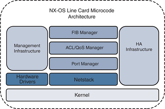
Figure 1-4 NX-OS Modular Line Card Microcode Architecture
During system boot, or if a card is inserted into the chassis, the supervisor decides if it should power on the card or not. This is done by checking the card type and verifying that the required power, software, and hardware resources are in place for the card to operate correctly. If so, the decision to power on the card is made. From that point, the line card powers on and executes its Basic Input/Output System (BIOS), power-on self-tests, and starts its system manager. Next, all the line card services are started that are required for normal operation. Communication and messaging channels are established to the supervisor that allow the supervisor to push the configuration and line card software upgrades as needed. Additional services are started for local handling of exception logging, management of environmental sensors, the card LEDs, health monitoring, and so on. After the critical system services are started, the individual ASICs are started, which allow the card to forward traffic.
In the operational state packets are forwarded and communications occur as needed with the supervisor to update counters, statistics, and environmental data. The line card has local storage for PSS as well as for On-Board Failure Logging (OBFL). The OBFL data is stored in nonvolatile memory so that it can survive reloads and is an excellent source of data for troubleshooting problems specific to the line card. Information such as exception history, card boot history, environmental history and much more is stored in the OBFL storage.
For day-to-day operations, there is typically no need to enter the line card CLI. The NX-OS operating system and distributed platforms are designed to be configured and managed from the supervisor module. There are some instances where direct access to the CLI of a line card is required. Typically, these scenarios also involve working with Cisco TAC to collect data and troubleshoot the various line card subsystems. In Example 1-8, the line card CLI is entered from the supervisor module using the attach module command. Notice that the prompt changes to indicate which module the user is currently connected to. After the user has entered the line card CLI, the show hardware internal dev-port-map command is issued, which displays the mapping of front panel ports to the various ASICs of the card on this Nexus 7000 M2 series card.
Example 1-8 Use of the attach module CLI from the Supervisor
Attaching to module 10 ...
To exit type 'exit', to abort type '$.'
module-10# show hardware internal dev-port-map
--------------------------------------------------------------
CARD_TYPE: 24 port 10G
>Front Panel ports:24
--------------------------------------------------------------
Device name Dev role Abbr num_inst:
--------------------------------------------------------------
> Skytrain DEV_QUEUEING QUEUE 4
> Valkyrie DEV_REWRITE RWR_0 4
> Eureka DEV_LAYER_2_LOOKUP L2LKP 2
> Lamira DEV_LAYER_3_LOOKUP L3LKP 2
> Garuda DEV_ETHERNET_MAC MAC_0 2
> EDC DEV_PHY PHYS 6
> Sacramento Xbar ASIC DEV_SWITCH_FABRIC SWICHF 1
+-----------------------------------------------------------------------+
+----------------+++FRONT PANEL PORT TO ASIC INSTANCE MAP+++------------+
+-----------------------------------------------------------------------+
FP port | PHYS | SECUR | MAC_0 | RWR_0 | L2LKP | L3LKP | QUEUE |SWICHF
1 0 0 0 0,1 0 0 0,1 0
2 0 0 0 0,1 0 0 0,1 0
3 0 0 0 0,1 0 0 0,1 0
4 0 0 0 0,1 0 0 0,1 0
5 1 0 0 0,1 0 0 0,1 0
6 1 0 0 0,1 0 0 0,1 0
7 1 0 0 0,1 0 0 0,1 0
8 1 0 0 0,1 0 0 0,1 0
9 2 0 0 0,1 0 0 0,1 0
10 2 0 0 0,1 0 0 0,1 0
11 2 0 0 0,1 0 0 0,1 0
12 2 0 0 0,1 0 0 0,1 0
13 3 1 1 2,3 1 1 2,3 0
14 3 1 1 2,3 1 1 2,3 0
15 3 1 1 2,3 1 1 2,3 0
16 3 1 1 2,3 1 1 2,3 0
17 4 1 1 2,3 1 1 2,3 0
18 4 1 1 2,3 1 1 2,3 0
19 4 1 1 2,3 1 1 2,3 0
20 4 1 1 2,3 1 1 2,3 0
21 5 1 1 2,3 1 1 2,3 0
22 5 1 1 2,3 1 1 2,3 0
23 5 1 1 2,3 1 1 2,3 0
24 5 1 1 2,3 1 1 2,3 0
+-----------------------------------------------------------------------+
+-----------------------------------------------------------------------+
Note
A common reason to access a line card’s CLI is to run embedded logic analyzer module (ELAM) packet captures on the local forwarding engine. ELAM is a tool used to troubleshoot data plane forwarding and hardware forwarding table programming problems. ELAM capture is outside the scope of this book.
File Systems
The file system is a vital component of any operating system, and NX-OS is no exception. The file system contains the directories and files needed by the operating system to boot, log events, and store data generated by the user, such as support files, debug outputs, and scripts. It is also used to store the configuration and any data that services store in nonvolatile PSS, which aids in system recovery after a failure.
Working with the NX-OS file system is similar to working with files in Cisco’s IOS, with some improvements. Files and directories are created and deleted from bootflash: or the external USB memory referred to as slot0:. Archive files are created and compress large files, like show techs, to save space. Table 1-1 provides a list of file system commands that are needed to manage and troubleshoot an NX-OS switch.
Table 1-1 File System Commands
Command |
Purpose |
pwd |
Displays the name of the current directory |
cd {directory | filesystem:[//module/][directory]} |
Changes to a new current directory |
dir [directory | filesystem:[//module/][directory]] |
Displays the directory contents |
mkdir [filesystem:[//module/]]directory |
Creates a new directory |
rmdir [filesystem :[//module/]]directory |
Deletes a directory |
move [filesystem:[//module/][directory /] | directory/]source-filename {{filesystem:[//module/][directory /] | directory/}[target-filename] | target-filename} |
Moves a file |
copy [filesystem:[//module/][directory/] | directory/]source-filename | {filesystem:[//module/][directory/]] | directory/}[target-filename] |
Copies a file |
delete {filesystem:[//module/][directory/] | directory/}filename |
Deletes a file |
show file [filesystem:[//module/]][directory/]filename |
Displays the contents of a file |
gzip [filesystem:[//module/][directory/] | directory/]filename |
Compresses a file |
gunzip [filesystem:[//module/] [directory/] | directory/]filename.gz |
Uncompresses a file |
tar create {bootflash: | volatile:}archive-filename [absolute] [bz2-compress] [gz-compress] [remove] [uncompressed] [verbose] filename-list |
Creates an archive file and adds files to it |
tar append {bootflash: | volatile:}archive-filename [absolute] [remove] [verbose] filename-list |
Adds files to an existing archive |
tar extract {bootflash: | volatile:}archive-filename [keep-old] [screen] [to {bootflash: | volatile:} [/directory-name]] [verbose] |
Extracts files from an existing archive |
Note
The gzip and tar options are useful when working with data collected during troubleshooting. Multiple files are combined into an archive and compressed for easy export to a central server for analysis.
Flash File System
The flash file system is used to store the system image and user-generated files. To see the contents of a directory in the file system, use the dir [directory | filesystem:[//module/][directory]] command. In Example 1-9, notice the NX-OS image files are present in the bootflash: directory.
Example 1-9 Output of the dir bootflash: Command
4096 May 02 18:57:24 2017 .patch/
7334 Jan 26 00:57:28 2017 LDP.txt
1135 Mar 02 02:00:38 2016 MDS201309060745595990.lic
580 Mar 02 02:00:12 2016 MDS201309060748159200.lic
584 Mar 02 01:59:01 2016 MDS201309060749036210.lic
552 Mar 02 01:56:02 2016 MDS201309071119059040.lic
1558 Apr 21 05:21:39 2017 eigrp_route_clear.txt
4096 Apr 29 09:37:44 2017 lost+found/
425228450 Jun 30 01:27:40 2017 n7000-s2-dk9.6.2.12.bin
580426199 Apr 06 20:08:12 2017 n7000-s2-dk9.7.3.1.D1.1.bin
67492267 Dec 06 02:00:13 2016 n7000-s2-epld.6.2.14.img
36633088 Jun 30 01:29:42 2017 n7000-s2-kickstart.6.2.12.bin
36708352 May 24 01:43:48 2017 n7000-s2-kickstart.6.2.18.bin
37997056 Apr 18 22:37:46 2017 n7000-s2-kickstart.7.2.2.D1.2.bin
46800896 Apr 06 20:07:20 2017 n7000-s2-kickstart.7.3.1.D1.1.bin
3028 Jun 13 00:06:22 2017 netflow_cap.pcap
0 Apr 21 02:11:19 2017 script_out.log
13 Apr 21 03:15:32 2017 script_output.txt
4096 Apr 18 19:35:28 2016 scripts/
17755 Mar 20 05:36:52 2016 startup-config-defaultconfig-DONOTDELETE
4096 Nov 11 00:30:10 2016 vdc_2/
4096 Apr 21 02:25:04 2017 vdc_3/
4096 Dec 05 19:07:18 2016 vdc_4/
4096 Apr 03 04:31:36 2016 vdc_5/
4096 Apr 12 22:26:42 2013 vdc_6/
4096 Apr 12 22:26:42 2013 vdc_7/
4096 Apr 12 22:26:42 2013 vdc_8/
4096 Apr 12 22:26:42 2013 vdc_9/
4096 Apr 18 19:33:57 2016 virtual-instance/
4096 Apr 18 20:36:58 2016 virtual-instance-stby-sync/
664 Jun 30 02:17:45 2017 vlan.dat
45137 Jun 30 01:33:45 2017 vtp_debug.log
Usage for bootflash://sup-local
1370902528 bytes used
445583360 bytes free
1816485888 bytes total
This provides the list of files and subdirectories on the currently active supervisor. For platforms with redundant supervisors, directories of the standby supervisor are accessed as demonstrated in Example 1-10 by appending //sup-standby/ to the directory path.
Example 1-10 Listing the Files on the Standby Supervisor
4096 Jun 12 20:31:56 2017 .patch/
1135 Mar 03 00:07:58 2016 MDS201309060745595990.lic
580 Mar 03 00:08:09 2016 MDS201309060748159200.lic
584 Mar 03 00:08:20 2016 MDS201309060749036210.lic
552 Mar 03 00:08:32 2016 MDS201309071119059040.lic
4096 May 24 01:27:09 2017 lost+found/
580426199 Apr 14 20:53:14 2017 n7000-s2-dk9.7.3.1.D1.1.bin
579340490 Jun 13 19:40:12 2017 n7000-s2-dk9.8.0.1.bin
36633088 Jun 30 01:49:14 2017 n7000-s2-kickstart.6.2.12.bin
36708352 May 24 01:17:23 2017 n7000-s2-kickstart.6.2.18.bin
37997056 Apr 18 22:37:46 2017 n7000-s2-kickstart.7.2.2.D1.2.bin
46800896 Apr 14 20:50:38 2017 n7000-s2-kickstart.7.3.1.D1.1.bin
8556 May 05 10:57:35 2017 pim-2nd.pcap
0 May 05 10:05:45 2017 pim-first
3184 May 05 10:12:24 2017 pim-first.pcap
4096 Apr 18 20:28:05 2016 scripts/
4096 May 19 22:42:12 2017 vdc_2/
4096 Jul 18 21:22:15 2016 vdc_3/
4096 Jul 18 21:22:49 2016 vdc_4/
4096 Mar 02 08:23:14 2016 vdc_5/
4096 Nov 28 05:52:06 2014 vdc_6/
4096 Nov 28 05:52:06 2014 vdc_7/
4096 Nov 28 05:52:06 2014 vdc_8/
4096 Nov 28 05:52:06 2014 vdc_9/
4096 Apr 18 19:46:52 2016 virtual-instance/
4096 Apr 18 20:40:29 2016 virtual-instance-stby-sync/
664 Jun 30 02:17:45 2017 vlan.dat
12888 Jun 12 20:34:40 2017 vtp_debug.log
Usage for bootflash://sup-standby
1458462720 bytes used
315793408 bytes free
1774256128 bytes total
Onboard Failure Logging
Onboard failure logging (OBFL) is a persistent storage available on Nexus platforms and is used to store operational information local to the card. Example 1-11 displays the different options that are enabled by default on a Nexus 7000 platform for an M2 I/O module. Having this persistent historical information is extremely useful for troubleshooting a module problem.
Example 1-11 Confirm OBFL Is Enabled on a Module
----------------------------
OBFL Status
----------------------------
Switch OBFL Log: Enabled
Module: 10 OBFL Log: Enabled
counter-stats Enabled
cpu-hog Enabled
credit-loss Enabled
environmental-history Enabled
error-stats Enabled
exception-log Enabled
interrupt-stats Enabled
mem-leak Enabled
miscellaneous-error Enabled
obfl-log (boot-uptime/device-version/obfl-history) Enabled
register-log Enabled
request-timeout Enabled
system-health Enabled
stack-trace Enabled
Note
The output in Example 1-11 is from a distributed platform; however, OBFL data is available for nondistributed platforms as well. The items enabled depend on the platform. Configure the OBFL options using the hw-module logging onboard configuration command with various subcommand options. There is typically no reason to disable OBFL.
Logflash
Logflash is a persistent storage location used to store system logs, syslog messages, debug output, and core files. On some Nexus platforms the logflash is an external compact flash or USB that may have not been installed, or was removed at some point. The system prints a periodic message indicating the logflash is missing to alert the operator about this condition so that it can be corrected. It is recommended to have the logflash mounted and available for use by the system so that any operational data is stored there. In the event of a problem, the persistent nature of logflash means that this data is available for analysis. Example 1-12 uses the show system internal flash to verify that logflash: is mounted and how much free space is available.
Example 1-12 Verifying the State and Available Space for the logflash:
Filesystem 1K-blocks Used Available Use% Mounted on
/dev/sda7 8256952 164288 7673236 3% /logflash
The contents of the logflash directory is examined using the dir logflash: as shown in Example 1-13.
Example 1-13 Verifying the Contents of the logflash: Directory
4096 Jun 05 17:43:10 2017 ISSU_debug_logs/
4096 May 19 13:00:36 2017 controller/
4096 Mar 30 14:03:38 2017 core/
4096 Mar 30 14:03:38 2017 debug/
4096 Jul 10 16:43:33 2017 debug_logs/
413807 Mar 30 14:02:21 2017 dme.log.2017.03.30.21.02.21.tar.gz
148751 Mar 31 12:21:01 2017 dme.log.2017.03.31.19.21.01.tar.gz
144588 May 19 12:58:31 2017 dme.log.2017.05.19.19.58.31.tar.gz
4096 Mar 30 14:03:38 2017 generic/
4096 Mar 30 13:58:28 2017 log/
16384 Mar 30 13:57:52 2017 lost+found/
4096 Jun 13 21:29:33 2017 vdc_1/
Usage for logflash://sup-local
597725184 bytes used
7857393664 bytes free
8455118848 bytes total
Example 1-14 demonstrates using the show file command to print the contents of a file in logflash:.
Example 1-14 Viewing the Contents of a Specific File in logflash:
2017 Mar 30 20:58:30 %VDC_MGR-5-VDC_STATE_CHANGE:
vdc 1 state changed to create in progress
2017 Mar 30 20:58:30 %VDC_MGR-5-VDC_STATE_CHANGE:
vdc 1 state changed to create pending
2017 Mar 30 20:58:31 Mar 30 20:58:30 %KERN-3-SYSTEM_MSG: [ 2726.358042]
biosinfo checksum failed expected ff Got 8 - kernel
2017 Mar 30 20:58:31 Mar 30 20:58:30 %KERN-3-SYSTEM_MSG: [ 2726.358044]
read_from_biosinfo: No Valid biosinfo - kernel
2017 Mar 30 20:58:31 %VMAN-2-INSTALL_STATE: Installing virtual service
'guestshell+'
2017 Mar 30 20:58:33 netstack: Registration with cli server complete
2017 Mar 30 20:58:48 %USER-2-SYSTEM_MSG:
ssnmgr_app_init called on ssnmgr up - aclmgr
2017 Mar 30 20:58:54 %USER-0-SYSTEM_MSG: end of default policer - copp
2017 Mar 30 20:58:54 %COPP-2-COPP_NO_POLICY: Control-plane is unprotected.
2017 Mar 30 20:58:56 %CARDCLIENT-2-FPGA_BOOT_PRIMARY: IOFPGA booted from Primary
2017 Mar 30 20:58:56 %CARDCLIENT-2-FPGA_BOOT_PRIMARY: MIFPGA booted from Primary
Understanding NX-OS Software Releases and Packaging
The publishing of a new NX-OS software version is categorized into one of three types of releases (Major/Minor/Maintenance). In general:
Major releases introduce significant new features, functions, and platforms.
Minor releases enhance the features and functions of an existing major release.
Maintenance releases address product defects in a minor release.
Depending on the Nexus platform and release, the naming convention of the software version varies. In early versions of NX-OS, each platform was built on its own NX-OS operating system code base. Today the majority of platforms use a NX-OS common base operating system. This common base code is then modified or augmented as needed to meet the feature requirements or hardware support of a specific platform. The advantage of this approach is that fixes for software defects in the platform independent base code are now incorporated back into the common base, and all platforms benefit from those fixes.
Figure 1-5 explains how to interpret the NX-OS software naming convention to recognize the Major/Minor/Maintenance release portions of the image name for a 6.2 release of NX-OS for the Nexus 7000 platform.
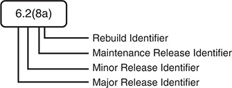
Figure 1-5 NX-OS Software Naming Convention
Figure 1-6 explains how to interpret the NX-OS software naming convention with the common platform independent base code and platform dependent release details for the Nexus 7000 platform.
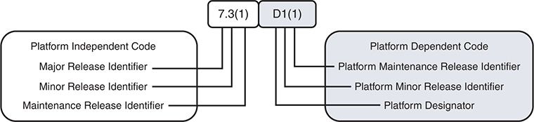
Figure 1-6 NX-OS Software Naming Convention with Platform Designator
The current NX-OS Platform Designators are as follows:
I—Nexus 9000 and 3000 common code base
D—Nexus 7000/7700
N—Nexus 5000/6000
U—Nexus 3000 for releases before the common code base
A—Nexus 3548
Note
The Nexus 3000 and Nexus 9000 series platforms now share a common platform-dependent software base, and the image name begins with nxos; for example, nxos.7.0.3.I6.1.bin.
In addition to the Major/Minor/Maintenance designation, releases are also classified as long-lived or short-lived releases, which describe their development life cycle. Long-lived releases are typically recommended over short-lived releases for most deployments when the required features and hardware are supported. Long-lived releases typically have more maintenance rebuilds that harden the software and add bug fixes with each new rebuild. Short-lived releases introduce new hardware or software features and receive maintenance releases as needed. Short-lived releases do not receive the same duration of support and have fewer maintenance rebuilds when compared with long-lived releases. The recommendation is to migrate away from a short-lived release when the feature requirements and hardware support are available in a long-lived release.
The NX-OS operating system is available on www.cisco.com; it consists of a kickstart image and a system image. Exceptions are the Nexus 9000 and Nexus 3000, which use a single system image file. For platforms that utilize the kickstart image, the kickstart image is booted first by the BIOS, and then the kickstart image loads the system image. For Nexus 3000 and Nexus 9000 platforms, a single binary file is booted directly.
Upgrading the Erasable Programmable Logic Device (EPLD) image is also possible on some platforms. The EPLD image is packaged separately from the NX-OS operating system. The EPLD image upgrades firmware on the hardware components of the I/O modules or line cards to offer new hardware functionality or to resolve known problems without having to replace the hardware.
Note
Not every NX-OS system upgrade requires an EPLD upgrade. The procedure for installing NX-OS software and EPLD images are documented with examples for each Nexus platform on www.cisco.com. Refer to the Software Upgrade and Installation Guides for more details.
Software Maintenance Upgrades
A recent addition to NX-OS is the capability to apply specific bug fixes as a patch to the currently installed software. This concept is familiar to those with experience on the Cisco IOS-XR platforms. NX-OS uses the same terminology.
The Software Maintenance Upgrade (SMU) feature allows network operators to apply a specific bug fix to their Nexus switch without requiring a system reload or in-service software upgrade (ISSU). Critical network environments do not upgrade software without extensive qualification testing specific to their architecture and configured features.
Previously if a bug fix was needed, a new maintenance release of NX-OS had to undergo qualification testing and then be rolled out to the network. This obviously adds delay waiting for the fix to be released in a maintenance release of NX-OS, as well as the delay accrued during qualification testing before the network was finally patched to eliminate the problem. This delay is solved with the SMU concept because only the SMU changes are applied to the already qualified base image. The SMU installation procedure leverages process restart or ISSU when possible to minimize impact to the network during installation. The Nexus switch then runs with the SMU applied until the specific bug fix is available in a qualified NX-OS maintenance release on Cisco.com.
Note
An SMU is valid only for the image it was created for. If the NX-OS software is upgraded to another release, the SMU is deactivated. It is critical to ensure any applicable software defects are fixed in the new version of software before performing an upgrade.
The SMU files are packaged as a binary and a README.txt that detail the associated bugs that are addressed by the SMU. The naming convention of the SMU file is platform-package_type.release_version.Bug_ID.file_type. For example, n7700-s2-dk9.7.3.1.D1.1.CSCvc44582.bin. The general procedure for installing a SMU follows:
Step 1. Copy the package file or files to a local storage device or file server.
Step 2. Add the package or packages on the device using the install add command.
Step 3. Activate the package or packages on the device using the install activate command.
Step 4. Commit the current set of packages using the install commit command. However, in case of the reload or ISSU SMU, commit the packages after the reload or ISSU.
Step 5. (Optional) Deactivate and remove the package, when desired.
Note
Before attempting the installation of an SMU, please review the detailed examples on www.cisco.com for the platform.
Licensing
NX-OS requires that the operator obtain and install appropriate license files for the features being enabled. Typically, Nexus platforms support a base feature set with no additional license requirements. This includes most Layer 2 functionality and generally some form of Layer 3 routing support. To enable advanced features, such as MPLS, OTV, FabricPath, FCoE, advanced routing, or VXLAN, additional licenses may need to be installed depending on the platform. In addition to feature licenses, several Nexus platforms also offer licenses to provide additional hardware capabilities. For example, SCALEABLE_SERVICES_PKT on the Nexus 7000 series enables XL-capable I/O modules to operate in XL mode and take full advantage of their larger table sizes. Another example is the port upgrade licenses available for some Nexus 3000 platforms.
License enforcement is built in to the NX-OS operating system by the feature manager, which disables services if the appropriate licenses are not present. If a specific feature is not configurable, the most likely culprit is a missing license. Cisco does allow for feature testing without a license by configuring the license grace-period in global configuration, which allows features to function for up to 120 days without the license installed. This does not cover all feature licenses on all platforms, however. Most notably the Nexus 9000 and Nexus 3000 do not support license grace-period.
License files are downloaded from www.cisco.com. To obtain a license file you need the serial number that is found with the show license host-id command. Next, use the product authorization key (PAK) from your software license claim to retrieve the license file and copy it to your switch. Installation of a license is a nondisruptive task and is accomplished with the install license command. For platforms that support virtual device contexts (VDC) the license is installed and managed on the default VDC and applies for all VDCs present on the chassis. The license installation is verified with the show license command.
NX-OS High-Availability Infrastructure
The system manager, MTS, and PSS infrastructure components that were described previously in this chapter provide NX-OS with the core of its high-availability infrastructure. This high-availability infrastructure enables NX-OS to seamlessly recover from most failure scenarios, such as a supervisor switchover or a process restart.
NX-OS is capable of restarting a service to recover and resume normal operation while minimizing impact to the data plane traffic being forwarded. This process restart event is either stateful or stateless and occurs when initiated by the user, or automatically when the system manager identifies a process failure.
In the event of a stateless restart, all the run-time data structures associated with the failed process are lost, and the system manager quickly spawns a new process to replace the one that failed. A stateful restart means that a portion of the run-time data is used to recover and seamlessly resume functioning where the previous process left off after a process failure or restart. Stateful restart is possible because the service updates its state in PSS while active and then recovers the important run-time data structures from PSS after a failure. Persistent MTS messages left in the process queue are picked up by the restarted service to allow a seamless recovery. The capability to resume processing persistent messages in the MTS queue means the service restart is transparent to other services that were communicating with the failed process.
NX-OS provides the infrastructure to the individual processes so that they can choose the type of recovery mechanism to implement. In some cases, a stateful recovery does not make sense, because a recovery mechanism is built in to the higher layers of a protocol. Consider a routing protocol process, such as OSPF or BGP, that has a protocol level graceful restart or nonstop forwarding implementation. For those protocols, it does not make sense to checkpoint the routing updates into the PSS infrastructure because they are recovered by the protocol.
Note
The reason for a reset is reviewed in the output of show system reset-reason. Process crash or restart details are viewed with the show processes log pid and show cores commands.
Supervisor Redundancy
Nexus platforms with redundant supervisor modules operate in an Active/Standby redundancy mode. This means that only one of the supervisors is active at a time, and the standby is ready and waiting to take over when a fatal failure of the active occurs. Active/Standby supervisor redundancy provides a fully redundant control plane for the device and allows for stateful switchover (SSO) and in-service software upgrades (ISSU). The current redundancy state and which supervisor is active is viewed in the output of show module, as well as the output of show system redundancy status, as shown in Example 1-15.
Example 1-15 Determining the Current Supervisor Redundancy State
Redundancy mode
---------------
administrative: HA
operational: HA
This supervisor (sup-1)
-----------------------
Redundancy state: Active
Supervisor state: Active
Internal state: Active with HA standby
Other supervisor (sup-2)
------------------------
Redundancy state: Standby
Supervisor state: HA standby
Internal state: HA standby
NX-1# show module
Mod Ports Module-Type Model Status
--- ----- ----------------------------------- ------------------ ----------
3 32 10 Gbps Ethernet Module N7K-M132XP-12 ok
5 0 Supervisor Module-2 N7K-SUP2E active *
6 0 Supervisor Module-2 N7K-SUP2E ha-standby
8 48 1000 Mbps Optical Ethernet Module N7K-M148GS-11 ok
9 48 1/10 Gbps Ethernet Module N7K-F248XP-25E ok
10 24 10 Gbps Ethernet Module N7K-M224XP-23L ok
When a redundant supervisor boots, the following events occur:
The Supervisor Active/Standby election is done.
The system manager process on the standby announces itself to the system manager process of the active.
The system manager of the standby synchronizes the startup configuration from the active and starts all services on the standby to mirror the active.
The services on the standby synchronize state with a snapshot of the services state on the active.
MTS messages from the services on the active are copied to the standby.
Services on the standby are now in sync with the active.
Process events are now copied to the standby so the services on both supervisors remain in sync during normal operation (event-based synchronization).
In the event of a supervisor switchover, services on the standby supervisor are notified by the system manager to recover state and prepare to take over the active role. Because the process events are synchronized to the standby by MTS during normal operation, the recovery occurs quickly. After the switchover is complete, the supervisor that was previously active is restarted, and it undergoes normal boot diagnostic tests. If diagnostic tests pass, and it boots successfully, it synchronizes using the same procedure previously outlined to synchronize with the current active supervisor. Figure 1-7 shows the relationship of the NX-OS services that make up the supervisor redundancy model.
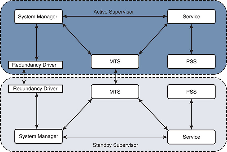
Figure 1-7 Supervisor Redundancy Model
In rare circumstances, the standby supervisor may fail to reach the HA Standby state. One possible reason is that a service on the standby is not able to synchronize state with the active. To check for this condition, verify the sysmgr state on the active and standby supervisor to confirm which service is not able to synchronize state. If multiple VDCs are configured, perform this verification for each VDC. To verify the synchronization state of the supervisors, use the show system internal sysmgr state command, as shown in Example 1-16.
Example 1-16 Confirm the Redundancy and Synchronization State
The master System Manager has PID 4862 and UUID 0x1.
Last time System Manager was gracefully shutdown.
The state is SRV_STATE_MASTER_ACTIVE_HOTSTDBY entered at time Fri Jun 30
01:48:40 2017.
The '-b' option (disable heartbeat) is currently disabled.
The '-n' (don't use rlimit) option is currently disabled.
Hap-reset is currently enabled.
Watchdog checking is currently enabled.
Watchdog kgdb setting is currently disabled.
Debugging info:
The trace mask is 0x00000000, the syslog priority enabled is 3.
The '-d' option is currently disabled.
The statistics generation is currently enabled.
HA info:
slotid = 5 supid = 0
cardstate = SYSMGR_CARDSTATE_ACTIVE .
cardstate = SYSMGR_CARDSTATE_ACTIVE (hot switchover is configured enabled).
Configured to use the real platform manager.
Configured to use the real redundancy driver.
Remote addresses: MTS - 0x00000601/3 IP - 127.1.1.6
MSYNC done.
Remote MSYNC not done.
Module online notification received.
Switchovers within threshold interval: 0
Last switchover time: 0 seconds after system start time
Cumulative time between last 0 switchovers: 0
Start done received for 1 plugins, Total number of plugins = 1
Statistics:
Message count: 0
Total latency: 0 Max latency: 0
Total exec: 0 Max exec: 0
The show system internal sysmgr gsync-pending command is used to verify that synchronization is complete. Any services that are still pending synchronization are listed in the output. Example 1-17 confirms that no services are pending synchronization on the active supervisor.
Example 1-17 Verify There Are No Services Pending Synchronization
The sysmgr output confirms that the superstate is stable for both supervisors, which indicates there is no problem currently. If there was a problem, the superstate displays as unstable. The superstate on the standby supervisor is verified by attaching to the standby supervisor module, as shown in Example 1-18.
Example 1-18 Verifying the Sysmgr State on the Standby Supervisor
Attaching to module 6 ...
The master System Manager has PID 4708 and UUID 0x1.
Last time System Manager was gracefully shutdown.
The state is SRV_STATE_MASTER_HOTSTDBY entered at time Fri Jun 30 01:49:50 2017.
The '-b' option (disable heartbeat) is currently disabled.
The '-n' (don't use rlimit) option is currently disabled.
Hap-reset is currently enabled.
Watchdog checking is currently enabled.
Watchdog kgdb setting is currently disabled.
Debugging info:
The trace mask is 0x00000000, the syslog priority enabled is 3.
The '-d' option is currently disabled.
The statistics generation is currently enabled.
HA info:
slotid = 6 supid = 0
cardstate = SYSMGR_CARDSTATE_STANDBY .
cardstate = SYSMGR_CARDSTATE_STANDBY (hot switchover is configured enabled).
Configured to use the real platform manager.
Configured to use the real redundancy driver.
Remote addresses: MTS - 0x00000501/3 IP - 127.1.1.5
MSYNC done.
Remote MSYNC done.
Module online notification received.
Switchovers within threshold interval: 0
Last switchover time: 0 seconds after system start time
Cumulative time between last 0 switchovers: 0
Start done received for 1 plugins, Total number of plugins = 1
Statistics:
Message count: 0
Total latency: 0 Max latency: 0
Total exec: 0 Max exec: 0
The superstate is stable, and the redundancy register indicates that this supervisor is redundancy state standby (RDN_ST_SB). Verify there are no services pending synchronization on the standby, as shown in Example 1-19.
Example 1-19 Verify There Are No Services Pending Synchronization
If a service that was pending synchronization was found in this output, the next step in the investigation is to verify the MTS queues for that particular service. An example of verifying the MTS queues for a service was demonstrated earlier in this chapter and is also shown in Chapter 3. If the MTS queue had messages pending for the service, further investigation into why those messages are pending is the next step in solving the problem. Network or device instability could be causing frequent MTS updates to the service that is preventing the synchronization from completing.
ISSU
NX-OS allows for in-service software upgrade (ISSU) as a high-availability feature. ISSU makes use of the NX-OS stateful switchover (SSO) capability with redundant supervisors and allows the system software to be updated without an impact to data traffic. During an ISSU, all components of the chassis are upgraded.
ISSU is initiated using the install all command, which performs the following steps to upgrade the system.
Step 1. Determines whether the upgrade is disruptive and asks if you want to continue
Step 2. Ensure that enough space is available in the standby bootflash
Step 3. Copies the kickstart and system images to the standby supervisor module
Step 4. Sets the KICKSTART and SYSTEM boot variables
Step 5. Reloads the standby supervisor module with the new Cisco NX-OS software
Step 6. Reloads the active supervisor module with the new Cisco NX-OS software, which causes a switchover to the newly upgraded standby supervisor module
Step 7. Upgrades the line cards
Step 8. The Connectivity Management Processor (CMP) on both supervisors get upgraded (Sup1 on Nexus 7000 only)
For platforms that do not have a redundant supervisor, such as the Nexus 5000 series, a different method is used to achieve ISSU. The control plane becomes inactive while the data plane continues to forward packets. This allows the supervisor CPU to reset without causing a traffic disruption and load the new NX-OS software version. After the CPU is booted on the new software release, the control plane is restored from the previous configuration and run-time state. The switch then synchronizes the control plane state to the data plane.
Nexus 9000 and Nexus 3000 platforms introduced an enhanced ISSU feature beginning in release 7.0(3)I5(1). Normally the NX-OS software runs directly on the hardware. However, with enhanced ISSU, the NX-OS software runs inside of a separate Linux container (LXC) for the supervisor and line cards. During enhanced ISSU, a third container is created to act as the standby supervisor so that the primary supervisor and line cards are upgraded without disruption to data traffic. This feature is enabled with the boot mode lxc configuration command on supported platforms.
Note
ISSU has restrictions on some platforms, and ISSU may not be supported between certain releases of NX-OS. Please reference the documentation on www.cisco.com to ensure ISSU is supported before attempting an upgrade with this method.
NX-OS Virtualization Features
As a modern data center class operating system, NX-OS and the Nexus switch platforms must provide support for virtualization of hardware and software resources to meet the demands of today’s network architectures. These features are introduced in this section and are explained in additional detail throughout this book.
Virtual Device Contexts
The Nexus 7000 platform allows the operator to partition a physical switch into multiple virtual switches known as Virtual Device Contexts (VDC). VDCs are an important virtualization feature where a physical switch is divided into multiple logical switches, and each logical switch serves a different role in the topology.
A common use case for VDC is with OTV or LISP, where a dedicated VDC is configured for the overlay encapsulation protocol, and another VDC serves to function as a distribution layer switch performing traditional Layer 2 and Layer 3 functions. Another popular use of the VDC concept is to have a production VDC and a test/development VDC to allow separation of these different environments in a single chassis. After appropriate planning and VDC creation, operators allocate ports to each VDC and then interconnect those ports to allow control plane protocols and data plane traffic to be exchanged between the VDCs.
The VDC architecture inherently means that some resources are global to the switch; other resources are shared between VDCs or dedicated to a specific VDC. For example, an OSPF process in VDC-1 is independent of an OSPF process in VDC-2, although they share the common CPU resources of the switch. The management Ethernet on the supervisor is shared among all VDCs. Specific ports on an I/O module are dedicated to a VDC, whereas the NX-OS kernel is global to the switch.
The logical separation between VDCs extends to the protocol stack; however, all VDCs on the switch share the same kernel resources and infrastructure. The system infrastructure is designed to allow fair resource allocation of shared resources, as well as the control plane queues from the kernel to the protocol stack of each VDC. Other resources are dedicated to a particular VDC, such as VLANs and routing table space. Figure 1-8 provides a visual representation of the VDC architecture of the Nexus 7000 series.
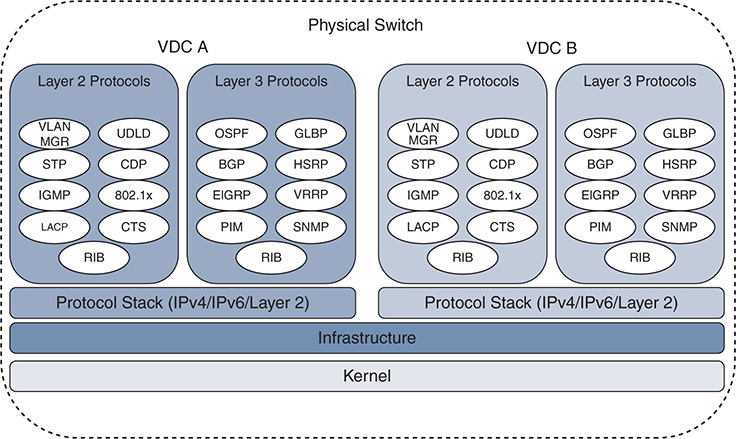
Figure 1-8 Nexus 7000 VDC Architecture
With appropriate licenses, the Supervisor 1 and Supervisor 2 allow for four VDCs plus an admin VDC. The Supervisor 2E allows for eight VDCs plus an admin VDC. The admin VDC does not handle any data plane traffic and serves only switch management functions. In the context of operating or troubleshooting in a VDC environment, note that certain tasks can be performed only from the default VDC.
In-service software upgrade/downgrade (ISSU/ISSD)
Erasable programmable logic devices (EPLD) upgrades
Control-plane policing (CoPP) configuration
Licensing operations
VDC configuration, including creation, suspension, deletion, and resource allocation
Systemwide QoS policy and port channel load-balancing configuration
Generic online diagnostics (GOLD) configuration
Ethanalyzer captures
Although VDCs allow additional versatility, some restrictions exist. For instance, all VDCs run on the same NX-OS version and kernel. Restrictions also exist on which I/O modules can be in the same VDC, and which ports of a line card can be allocated to a VDC based on the hardware application-specific integrated circuit (ASIC) architecture of the I/O module and forwarding engine. Before attempting to create VDCs, check the documentation for the specific supervisor and I/O modules that are installed in the switch so that any limitations are dealt with in the design and planning phase.
Note
At the time of this writing, multiple VDCs are supported only on the Nexus 7000 series.
Virtual Routing and Forwarding
Virtual Routing and Forwarding (VRF) instances have proven very useful for logical separation of network resources. The purpose of a VRF is to allow multiple instances of control plane and data plane forwarding tables to operate simultaneously on a single device while remaining logically separated.
The concept of VRF-lite defines multiple routing and forwarding tables with logical separation on a single device without a Multiprotocol Label Switching (MPLS) transport. MPLS VPNs use VRFs on provider edge (PE) nodes to separate multiple routing and forwarding tables logically with an MPLS transport between PEs.
NX-OS supports both VRF-lite and MPLS VPN for virtualization and separation of routing tables and forwarding state. Importing and exporting routes between VRF contexts is supported, as well as import and export from the global routing table to a VRF table. In addition to the user-defined VRFs, NX-OS puts the management Ethernet interface of the switch into its own management VRF by default. This provides a desirable separation of data plane and management plane services.
In the virtualization hierarchy, a VRF exists locally within a VDC, and multiple VDCs can exist in a physical switch. If VRFs configured in different VDCs need to communicate, a control plane routing protocol is required to exchange information between the VRFs in different VDCs. This is done in the same manner as routing between VDCs using the default VRF. Routing traffic between VRFs is achieved with a control plane protocol to exchange routing information, or if the VRFs exist in the same VDC, route leaking is used to exchange routes between them.
Note
Support for MPLS VPN is dependent upon the capabilities of the platform and the installed feature licenses.
Virtual Port Channel
Virtual port channels (vPC) allow a pair of peer switches to connect to a third device and appear as a single switch. The only requirement for the third device is that it must support IEEE 802.3ad port channels. No special configuration is needed to operate with a vPC switch pair, which makes this technology a very attractive option to remove STP blocking ports from the access layer. When two switches are configured as a vPC pair, one switch is elected primary (lowest priority wins). The primary role comes into play for STP, as well as during certain failure scenarios.
Figure 1-9 is an example of a vPC-enabled switch pair connected with two additional switches using vPC.
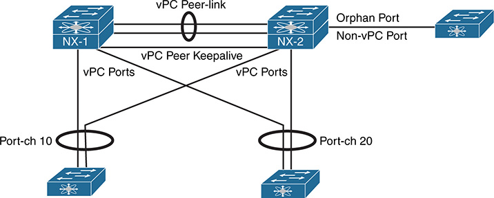
Figure 1-9 The vPC Architecture
In Figure 1-9, the vPC pair is using vPC Port-channel 10 and vPC Port-channel 20 to connect with two access switches. A third access switch to the right of NX-2 is not connected in vPC mode. This non-vPC enabled interface is known as an orphan port in vPC terminology. Each of the vPC terms in Figure 1-9 are as follows:
vPC Peer-link is configured to carry all user-defined VLANs. It is also used to forward BPDUs, HSRP hellos, and CFS (Cisco Fabric Services) protocol packets between vPC peer switches. It should be a port channel with member links on different modules for redundancy purposes.
vPC Peer Keepalive link should be a separate path from the peer-link. It does not have to be a point-to-point link and can traverse a routed infrastructure. The peer keepalive link is used to ensure liveness of the vPC peer switch.
Orphan Port is a non-vPC port connected to a device in the vPC topology.
vPC Port (vPC member ports) are ports assigned to a vPC Port-channel group. The ports of the vPC are split between the vPC peers.
Because all links are up and forwarding in vPC, the decision of which vPC member-link interface to forward a packet on is made by the port-channel load-balance hash of the device sending the packet. The sending switch looks at the frame source and destination addresses of a traffic flow and feeds these details into an algorithm. The algorithm performs a hash function and returns a selected member port of the port-channel for the frame to exit on. This allows all member link interfaces of the port-channel to share the load of traffic.
Historically, routing protocol adjacencies had limitations when configured to operate over a vPC topology. Recent versions of NX-OS have made changes that allow dynamic unicast routing protocols to operate over vPC without the limitations that existed previously. Check the vPC configuration guide of the platform to ensure support exists before attempting this configuration.
With each vPC peer making independent frame forwarding decisions, there is a need for state synchronization between the peers. CFS is the protocol that is used to synchronize Layer 2 (L2) state. It operates over the peer-link and is enabled automatically. Its role is to ensure compatibility of the vPC member ports between vPC peers. It is also used to synchronize mac address tables and IGMP snooping state between vPC peers so that any table entries exist on both vPC peers. Layer 3 (L3) forwarding tables and protocol state are independent on each vPC peer.
Note
vPC is introduced here as a virtualization concept and is covered in detail later in this book.
Management and Operations Capabilities
The following section introduces some of the operational, serviceability, and usability features of the Nexus switching platforms. These features were designed to improve the user experience and ease operational tasks associated with configuring, troubleshooting, and performing maintenance on Nexus switches.
NX-OS Advanced CLI
The NX-OS CLI was originally designed to have an IOS-like look and feel. At a high level the two CLI interfaces are very similar. IOS and NX-OS both have the concept of an executive mode, different user privileges, a running configuration, and a startup configuration, to name a few. NX-OS and IOS show commands and debugs are in many cases the same from one operating system to the other. However, NX-OS includes additional command-line enhancements and utilities that make operating and troubleshooting easier and more productive on NX-OS.
During the process of investigating a problem, data is often collected for offline analysis. This means that the user needs to execute commands, capture the output, and then transfer that output from the device to somewhere else for review. NX-OS provides the > and >> operators, as shown in Example 1-20, which allow output to be redirected to a new file or appended to an existing file, respectively. This is especially useful when collecting a lengthy show tech support file.
Example 1-20 show Command Output Redirection
NX-1# dir bootflash: | inc netstack
23144888 Jul 13 16:09:09 2017 tech_netstack.txt
The use of the parsing utilities (i.e. “| count” and “| wc”) provide a way of counting the number of lines or words in the show command being executed. Example 1-21 shows how to use this for situations where a simple count provides verification of the current state; for example, comparing the number of lines in show ip ospf neighbor before and after a configuration change.
Example 1-21 Using the Count or WC Utilities
There are many troubleshooting scenarios where command output needs to be taken multiple times and compared to see what has changed or which counters have incremented since the previous execution. Example 1-22 demonstrates the use of the diff utility. Do not use this for large outputs such as show tech, because it consumes system resources while retaining the output for comparison. It is better to compare large outputs after transferring the data off-box.
22,24c22,24
< 30 seconds input rate 360 bits/sec, 0 packets/sec
< 30 seconds output rate 112 bits/sec, 0 packets/sec
< input rate 360 bps, 0 pps; output rate 112 bps, 0 pps
---
> 30 seconds input rate 336 bits/sec, 0 packets/sec
> 30 seconds output rate 72 bits/sec, 0 packets/sec
> input rate 336 bps, 0 pps; output rate 72 bps, 0 pps
34,35c34,35
< 468 unicast packets 183033 multicast packets 1 broadcast packets
< 183506 input packets 18852532 bytes
---
> 468 unicast packets 183034 multicast packets 1 broadcast packets
> 183507 input packets 18852610 bytes
In some cases it is desirable to obtain only the last few lines of a command instead of paging through the output or using an include/exclude utility option. The last count utility displays the last few entries and is used when parsing the accounting log, system log buffer, or event history logs. Example 1-23 shows how to print only the last line in the log buffer.
2017 Jul 13 21:57:15 F340-35-02-N7K-7009-A %VSHD-5-VSHD_SYSLOG_CONFIG_I:
Configured from vty by admin on console0
Another nice feature is the “,” utility, which is used to execute a command with multiple arguments. Example 1-24 shows how this is useful for checking the interface rate simultaneously on two different ports when combined with egrep.
Example 1-24 Executing a Command with Multiple Arguments
Load-Interval #1: 30 seconds
30 seconds input rate 64680 bits/sec, 11 packets/sec
30 seconds output rate 67304 bits/sec, 11 packets/sec
Load-Interval #1: 30 seconds
30 seconds input rate 66288 bits/sec, 11 packets/sec
30 seconds output rate 64931 bits/sec, 11 packets/sec
The egrep and grep utilities are extremely useful for removing clutter in a command output to show only the character pattern of interest. Example 1-25 demonstrates a common use for egrep, which is to review an event history log and look for a specific event. In this example, egrep is used to find each time OSPF has run its shortest path first (SPF) algorithm. The prev 1 option is used so that the line previous to the pattern match is printed, which indicates a full or partial SPF run. The next option is used to get lines after the egrep pattern match.
Example 1-25 Using Egrep to Parse an Event History
2017 Jul 9 23:46:00.646652 ospf 12 [16161]: : Examining summaries
2017 Jul 9 23:46:00.646644 ospf 12 [16161]: : SPF run 12 STARTED with flags
0x4, vpn superbackbone changed flag is FALSE
--
2017 Jul 9 23:44:05.194089 ospf 12 [16161]: : This is a full SPF
2017 Jul 9 23:44:05.194087 ospf 12 [16161]: : SPF run 11 STARTED with flags
0x1, vpn superbackbone changed flag is FALSE
--
2017 Jul 9 23:44:00.094088 ospf 12 [16161]: : This is a full SPF
2017 Jul 9 23:44:00.094085 ospf 12 [16161]: : SPF run 10 STARTED with flags
0x1, vpn superbackbone changed flag is FALSE
--
2017 Jul 9 23:43:56.074094 ospf 12 [16161]: : This is a full SPF
2017 Jul 9 23:43:56.074091 ospf 12 [16161]: : SPF run 9 STARTED with flags
0x1, vpn superbackbone changed flag is FALSE
--
Egrep has several other useful options that you should become familiar with. They are count, which returns a count of the number of matches, invert-match, which prints only lines that do not match the pattern, and line-number, which appends the line number of the match to each line.
Table 1-2 provides information on additional command utilities available in NX-OS.
Table 1-2 Additional Command Utilities
Utility |
Purpose |
no-more |
Command output pages without the need to press return or space when the terminal length is reached. |
json |
Command output is printed as JSON. This is useful when data will be collected and then consumed by a script or software application because the output is structured data. |
xml |
Prints the output in XML format. |
Command output is sent via email. |
|
include |
Only lines that match the pattern are printed. |
exclude |
Only lines that do not match the pattern are printed. |
section |
The section of output containing the pattern is printed. |
Example 1-26 demonstrates show cli list [string], which returns all CLI commands that match the given string input. This saves time over using the “?” to figure out which commands exist.
Example 1-26 Using show cli list Command
show logging level ospf
show tech-support ospf brief
show tech-support ospf
show ip ospf <str> vrf <str>
show ip ospf <str> vrf <str>
show ip ospf <str> vrf all
show ip ospf <str>
show ip ospf <str> neighbors <if> <ip>
show ip ospf <str> neighbors <if> <str>
show ip ospf <str> neighbors <if>
show ip ospf <str> neighbors <ip> vrf <str>
show ip ospf <str> neighbors <ip> vrf <str>
show ip ospf <str> neighbors <ip> vrf all
Complementary to the previous example, the syntax for the identified CLI commands are available with the show cli syntax [string] command, as shown in Example 1-27.
Example 1-27 Using show cli syntax Command
(0) show logging level ospf
(1) show tech-support ospf [ brief ]
(2) show ip ospf [ <tag> ] [ vrf { <vrf-name> | <vrf-known-name> | all } ] [ ]
(3) show ip ospf [ <tag> ] ha [ vrf { <vrf-name> | <vrf-known-name> | all } ] [ ]
(4) show ip ospf [ <tag> ] neighbors [ { { <interface> [ <neighbor> | <neighbor-
name> ] } | { [ <neighbor> | <neighbor-name> ] [ vrf { <vrf-
name> | <vrf-known-name> | all } ] } } ] [ ]
The show running-config diff command is useful to quickly compare the running-configuration and the startup-configuration of the switch. In Example 1-28 a logging logfile was configured and is highlighted with the “!” in the output as a changed line between the two files.
Example 1-28 Using show running-config diff
*** Startup-config
--- Running-config
***************
*** 318,328 ****
boot kickstart bootflash:/n7000-s2-kickstart.7.2.2.D1.2.gbin sup-2
boot system bootflash:/n7000-s2-dk9.7.2.2.D1.2.gbin sup-2
mpls ldp configuration
router-id Lo0 force
no system auto-upgrade epld
router ospf 12
router-id 172.16.0.1
--- 317,327 ----
boot kickstart bootflash:/n7000-s2-kickstart.7.2.2.D1.2.gbin sup-2
boot system bootflash:/n7000-s2-dk9.7.2.2.D1.2.gbin sup-2
mpls ldp configuration
router-id Lo0 force
no system auto-upgrade epld
router ospf 12
router-id 172.16.0.1
Cisco IOS requires that you prepend any user or exec level command with do while in the configuration mode. NX-OS eliminates the need for the do command because it allows the execution of exec level commands from within the configuration mode.
Technical Support Files
The concept of a show tech-support CLI command is likely familiar to anyone who has worked on Cisco router or switch platforms. The general idea of a show tech support file is to capture common outputs related to a problem for offline analysis. NX-OS offers a very useful show tech support hierarchy. At the top level is the show tech details, which obtains and aggregates many commonly needed feature show tech files, event histories, and internal data structures with a single CLI command. Another useful command is the tac-pac, which collects the show tech details output and automatically stores it as a compressed file in bootflash:.
Each feature enabled in NX-OS has the capability to provide a tech-support file that obtains the most useful information about that specific feature. The show tech-support [feature] obtains the feature configuration, show commands, data structures, and event histories needed for offline analysis of a problem with a specific feature. Be aware of feature dependencies when performing data collection so that all relevant information about the problem is gathered.
For example, a unicast routing problem with OSPF as the routing protocol requires you to collect show tech-support ospf, but for a complete analysis the output of show tech-support routing ip unicast is also needed to get Unicast Routing Information Base (URIB) events. Feature dependency and what to collect is determined on a case-by-case basis, depending on the problem under investigation. Many feature show tech-support outputs do not include a full show running-config.
It is always a good idea to collect the full show running-config along with any specific feature show techs that are needed. Example 1-29 shows the collection of show tech-support commands and the running-configuration to investigate a unicast routing problem with OSPF.
Example 1-29 Collecting Show Tech-Support to Investigate an OSPF Problem
NX-1# show tech-support routing ip unicast > tech_routing.txt
NX-1# show tech-support ospf > tech_ospf.txt
NX-1# show running-config > bootflash:running-config
NX-1# tar create bootflash:routing-issue-data bootflash:tech_l3_unicast.txt bootflash:tech_ospf.txt
bootflash:tech_routing.txt bootflash:running-config
NX-1# dir | inc routing|tech|running
578819 Jul 13 00:15:24 2017 routing-issue-data.tar.gz
2743 Jul 13 00:12:38 2017 running-config
8357805 Jul 12 23:57:46 2017 tech_l3_unicast.txt
151081 Jul 12 23:58:04 2017 tech_ospf.txt
396743 Jul 12 23:58:39 2017 tech_routing.txt
Notice that each show tech is collected as an individual file by redirecting the output to bootflash: with the “>” operator. After collecting all the relevant feature show techs, they are combined into an archive using the tar command, which makes the data easy to copy from the switch for later analysis.
Note
In addition to the show tech-support [feature], NX-OS also provides show running-config [feature], which prints only the running-configuration of the given feature.
Accounting Log
NX-OS keeps a history of all configuration changes made to the device in the accounting log. This is a useful piece of information to determine what has changed in a switch, and by whom. Typically, problems are investigated based on the time when they started to occur, and the accounting log can answer the question, What has changed? An example of reviewing the accounting log is shown in Example 1-30. Because only the last few lines are of interest, the start-seqnum option is used to jump to the end of the list.
Example 1-30 Examining the Accounting Log
<CR>
<0-250000> Log Size(in bytes)
> Redirect it to a file
>> Redirect it to a file in append mode
all Display accounting log including show commands (Use <terminal
log-all> to enable show command accounting)
last-index Show accounting log last index information
nvram Present in nvram
start-seqnum Show messages starting from a given sequence number
start-time Show messages from a given start-time
| Pipe command output to filter
NX-01# show accounting log last-index
Last Log cleared/wrapped time is : Fri Sep 9 10:14:48 2016
25709:Thu Jul 13 00:04:41 2017:update:console0:admin:switchto ; dir | inc routin
g|tech (SUCCESS)
25710:Thu Jul 13 00:13:30 2017:update:console0:admin:switchto ; dir | inc routin
g|tech|running (SUCCESS)
25711:Thu Jul 13 00:15:24 2017:update:console0:admin:switchto ; tar create bootf
lash:/routing-issue-data bootflash:/tech_l3_unicast.txt bootflash:/tech_ospf.txt
bootflash:/tech_routing.txt bootflash:/running-config (SUCCESS)
25712:Thu Jul 13 00:15:30 2017:update:console0:admin:switchto ; dir | inc routin
g|tech|running (SUCCESS)
The accounting log is stored persistently in logflash: so that it is available even if the switch is reloaded.
Note
The terminal log-all configuration command enables the logging of show commands in the accounting log.
Feature Event-History
One very useful serviceability feature of NX-OS is that it keeps circular event-history buffers for each configured feature. The event-history is similar in many ways to an always-on debug for the feature that does not have any negative CPU impact on the switch. The granularity of events stored in the event-history depends on the individual feature, but many are equivalent to the output that is obtained with debugging. In many cases, the event-history contains enough data to determine what sequence of events has occurred for the feature without the need for additional debug logs, which makes them a great troubleshooting resource.
Event-history buffers are circular, which means that the possibility exists for events to be overwritten by the time a problem condition is recognized, leaving no event history evidence to investigate. For some features, the event-history size is configurable as [small | medium | large]. If a problem with a particular feature is occurring regularly, increase the event-history size to improve the chance of catching the problem sequence in the buffer. Most feature event-histories are viewed with the show {feature} internal event-history command, as shown in Example 1-31.
Example 1-31 Reviewing the OSPF Adjacency Event History
event EXCHDONE
2017 Jul 12 23:30:55.816386 ospf 1 [5817]: : seqnr 0x385a2ae7, dbdbits 0, mtu
1500, options 0x42
2017 Jul 12 23:30:55.816381 ospf 1 [5817]: : Got DBD from 192.168.1.2 with 0
entries
2017 Jul 12 23:30:55.816372 ospf 1 [5817]: : seqnr 0x385a2ae7, dbdbits 0, mtu
1500, options 0x42
2017 Jul 12 23:30:55.816366 ospf 1 [5817]: : Got DBD from 192.168.1.2 with 0 ent ries
2017 Jul 12 23:30:55.814575 ospf 1 [5817]: : mtu 1500, opts: 0x42, ddbits: 0x1,
seq: 0x385a2ae7
2017 Jul 12 23:30:55.814572 ospf 1 [5817]: : Sent DBD with 0 entries to
192.168.1.2 on Vlan2
2017 Jul 12 23:30:55.814567 ospf 1 [5817]: : Sending DBD to 192.168.1.2 on Vlan2
Note
Troubleshooting scenarios may require a periodic dump of the feature tech support file. This is done with Embedded Event Manager (EEM), or another method of scripting the data collection. bloggerd is another tool for such scenarios, but it is recommended for use only under guidance from Cisco Technical Assistance Center (TAC).
Debug Options: Log File and Filters
If a feature’s event history is not granular enough to troubleshoot a problem, or if you are not able to capture the event history before the relevant events are lost due to roll over, feature-specific debugs can be used. Debugs are enabled with filters and logged to a debug log file. Example 1-32 demonstrates a debug filter and debug log file to filter the output for only a particular OSPF neighbor.
Example 1-32 Debug Log File and Debug Filter
NX-1# debug logfile ospf-debug-log
NX-1# debug ip ospf adjacency detail
NX-1# dir log: | inc ospf
1792 Jul 13 00:49:40 2017 ospf-debug-log
NX-1# show debug logfile ospf-debug-log
2017 Jul 13 00:49:14.896199 ospf: 1 [5817] (default) Nbr 192.168.1.2
FSM start: old state FULL, event HELLORCVD
2017 Jul 13 00:49:14.896376 ospf: 1 [5817] (default) Nbr 192.168.1.2:
FULL --> FULL, event HELLORCVD
2017 Jul 13 00:49:14.896404 ospf: 1 [5817] (default) Nbr 192.168.1.2
FSM start: old state FULL, event TWOWAYRCVD
2017 Jul 13 00:49:14.896431 ospf: 1 [5817] (default) Nbr 192.168.1.2:
FULL --> FULL, event TWOWAYRCVD
Configuration Checkpoint and Rollback
NX-OS supports the capability to create configuration checkpoints. These checkpoints are a way of storing a known good configuration for the system so that if a configuration change is made that introduces an undesirable behavior, it is quickly rolled back to a known good configuration without a system reload. This approach removes the error-prone human element and saves you from having to copy and paste the previous configuration back into the device. There are four types of configuration rollback.
Atomic: Perform the rollback only if no errors occur. This is the default option.
Best-effort: Perform the rollback and skip any errors.
Stop-at-first-failure: Perform the rollback but stop if an error occurs.
Verbose mode: Shows the detailed execution log during the rollback operation.
When performing a configuration rollback, the changes to be applied are viewed with the show diff rollback-patch checkpoint command. This allows a checkpoint file to be compared to another checkpoint file, or to the running configuration. During a rollback, if an error is encountered, you need to decide to cancel or continue. If the rollback is canceled, a list of changes that were applied is provided, and those changes need to be backed out manually to return to the pre-rollback configuration. Example 1-33 provides an example of a configuration checkpoint and rollback operation.
Example 1-33 Configuration Checkpoint and Rollback
...............Done
NX-1# show diff rollback-patch checkpoint known_good running-config
Collecting Running-Config
#Generating Rollback Patch
Enter configuration commands, one per line. End with CNTL/Z.
NX-1(config)# no router ospfv3 1
NX-1(config)# end
NX-1# show diff rollback-patch checkpoint known_good running-config
Collecting Running-Config
#Generating Rollback Patch
!!
Note: Applying config parallelly may fail Rollback verification
Collecting Running-Config
#Generating Rollback Patch
Executing Rollback Patch
Generating Running-config for verification
Generating Patch for verification
Verification is Successful.
Collecting Running-Config
#Generating Rollback Patch
In Example 1-33, an OSPFv3 process was deleted after creating the initial configuration checkpoint. The difference between the checkpoint and the running configuration was highlighted with the show diff rollback-patch checkpoint command. The configuration change was then rolled back successfully and the OSPFv3 process was restored.
Consistency Checkers
Consistency checkers are an example of how NX-OS platforms are improving serviceability in each release. Certain software bugs or race conditions may result in a mismatch of state between the control plane, data plane, or forwarding ASICs. Finding these problems is nontrivial and usually requires in-depth knowledge of the platform. Consistency checkers were introduced to deal with these situations, and they are the result of feedback from TAC and customers. Example 1-34 shows the usage of the forwarding consistency checker on a Nexus 3172 platform.
Example 1-34 Executing the Consistency Checker
NX-1# show consistency-checker forwarding ipv4
IPV4 Consistency check : table_id(0x1)
Execution time : 73 ms ()
The type of consistency checkers that are available vary by platform. In addition, the capabilities are continuing to evolve, and support is being added for new protocols and platforms with each release. Consistency checkers are run on-demand while investigating a problem that has been isolated to the specific device. They quickly validate that a problem is not caused by a state mismatch in the platform.
Feature Scheduler, EEM, and Python
NX-OS supports a scheduler feature that allows commands or scripts to be executed in a non-interactive mode at a defined start time and frequency. The scheduler does not require any special license to run.
The scheduler is a useful feature for backing up configurations, copying files, or collecting data at a specified time interval. The scheduler feature can be combined with the NX-OS python or Embedded Event Manager (EEM) to provide a powerful method of automating tasks. In Example 1-35, a scheduler job is defined that executes a python script every day at midnight. The scheduler configuration requires that feature scheduler is enabled. The job and schedule for the job is then configured to determine when the job executes.
Example 1-35 Configuring a Scheduler Job
feature scheduler
scheduler job name run_script
source /bootflash/scripts/snapshot_compare.py
end-job
scheduler schedule name at_midnight
job name run_script
time daily 00:00
NX-OS provides access to the python interpreter from the exec mode CLI by using the python command, as shown in Example 1-36.
Example 1-36 NX-OS Python Interpreter
Python 2.7.5 (default, Jun 3 2016, 03:57:06)
[GCC 4.6.3] on linux2
Type "help", "copyright", "credits" or "license" for more information.
In addition to python, NX-OS also supports EEM, which is another way of automating tasks such as data collection, or dynamically modifying the configuration if a defined event has occurred.
Note
Chapter 15, “Programmability and Automation,” covers the programming and automation capabilities of NX-OS in more detail.
Bash Shell
A recent addition to NX-OS is the bash shell feature. After feature bash-shell is enabled, the user can enter the Linux bash shell of the NX-OS operating system. Example 1-37 shows how to access the bash shell from the exec prompt.
Example 1-37 Entering the Bash Shell
bash-4.2$ pwd
/bootflash/home/admin
bash-4.2$ uname -srvo
Linux 3.4.43-WR5.0.1.13_standard #1 SMP Thu Apr 7 08:39:09 PDT 2016 GNU/Linux
bash-4.2$
To gain access to the bash shell, your user account must be associated to the dev-ops or network-admin role. Bash commands can also be run from the exec mode CLI of the switch with the run bash [command] option. This command takes the command argument specified, runs it in the bash shell, and returns the output. Python scripts can run from within the bash shell as well. It is recommended to use caution while utilizing the bash shell to manage the device.
Summary
NX-OS is a powerful, feature-rich network operating system that is deployed in thousands of networks around the world. For the past 10 years, it has remained under constant development to meet the needs of those networks as they evolve over time. The modular architecture allows for rapid feature development and source code sharing between the different Nexus switching platforms. NX-OS and Nexus switches are designed for resilience of both the hardware and software to allow for uninterrupted service even in the event of a component failure.
The important management and operational features of NX-OS were introduced in this chapter. That foundational knowledge enables you to apply the troubleshooting techniques from the remaining chapters to your own network environment.
References
Fuller, Ron. “Virtual Device Context (VDC) Design and Implementation” (presented at Cisco Live, San Francisco 2014).
Fuller, Ron. “Cisco NX-OS Software Architecture” (presented at Cisco Live, Orlando 2013).
Esau, Matthew and Souvik Ghosh. “Advanced Troubleshooting Cisco 7000 Series” (presented at Cisco Live, Las Vegas 2017).
Fuller, Ron, David Jansen, and Matthew McPherson. NX-OS and Cisco Nexus Switching. Indianapolis: Cisco Press, 2013.
Cisco. Cisco Nexus Platform Product Data Sheets, www.cisco.com.
Cisco. Cisco Nexus Platform Configuration Guides, www.cisco.com.
Cisco. Cisco Nexus Platform Software Upgrade and Installation Guides, www.cisco.com.