
In this chapter
Object diagrams model the instances of things contained in class diagrams. An object diagram shows a set of objects and their relationships at a point in time.
You use object diagrams to model the static design view or static process view of a system. This involves modeling a snapshot of the system at a moment in time and rendering a set of objects, their state, and their relationships.
Object diagrams are not only important for visualizing, specifying, and documenting structural models, but also for constructing the static aspects of systems through forward and reverse engineering.
If you are not used to the game, soccer looks like a terribly simple sport—an unruly mob of people madly running about a field chasing a white ball. Looking at the blurred image of bodies in motion, there hardly seems to be any subtlety or style to it.
Freeze the motion for a moment, then classify the individual players, and a very different picture of the game emerges. No longer just a mass of humanity, you'll be able to distinguish the forwards, halfbacks, and fullbacks. Dig a bit deeper and you'll understand how these players collaborate: following strategies for goal-tending, moving the ball, stealing the ball, and attacking. In a winning team, you won't find players placed randomly around the field.
Instead, at every moment of the game, you'll find their placement on the field and their relationship to other players well calculated.
Trying to visualize, specify, construct, or document a software-intensive system is similar. If you were to trace the control flow of a running system, you'd quickly lose sight of the bigger picture for how the system's parts are organized, especially if you have multiple threads of control. Similarly, if you have a complex data structure, just looking at the state of one object at a time doesn't help much. Rather, you need to study a snapshot of the object, its neighbors, and its relationships to these neighbors. In all but the simplest object-oriented systems, you'd find a multitude of objects present, each standing in precise relationship with others. In fact, when an object-oriented system breaks, it's typically not because of a failure in logic, but because of broken connections among objects or a mangled state in individual objects.
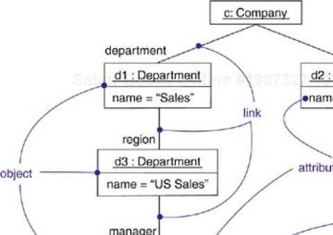
With the UML, you use class diagrams to visualize the static aspects of your system's building blocks. You use interaction diagrams to visualize the dynamic aspects of your system, consisting of instances of these building blocks and messages dispatched among them. An object diagram covers a set of instances of the things found in a class diagram. An object diagram, therefore, expresses the static part of an interaction, consisting of the objects that collaborate but without any of the messages passed among them. In both cases, an object diagram freezes a moment in time, as in Figure 14-1.
An object diagram is a diagram that shows a set of objects and their relationships at a point in time. Graphically, an object diagram is a collection of vertices and arcs.
An object diagram is a special kind of diagram and shares the same common properties as all other diagrams—that is, a name and graphical contents that are a projection into a model. What distinguishes an object diagram from all other kinds of diagrams is its particular content.
Object diagrams commonly contain
Like all other diagrams, object diagrams may contain notes and constraints.
Sometimes you'll want to place classes in your object diagrams as well, especially when you want to visualize the classes behind each instance.
Note
An object diagram correlates with a class diagram: The class diagram describes the general situation, and the instance diagram describes specific instances derived from the class diagram.An object diagram contains primarily objects and links. Deployment diagrams may also occur in generic and instance forms: General deployment diagrams describe node types, and instance deployment diagrams describe a concrete configuration of node instances described by those types.
You use object diagrams to model the static design view or static process view of a system just as you do with class diagrams, but from the perspective of real or prototypical instances. This view primarily supports the functional requirements of a system—that is, the services the system should provide to its end users. Object diagrams let you model static data structures.
When you model the static design view or static interaction view of a system, you typically use object diagrams to model object structures.
Modeling object structures involves taking a snapshot of the objects in a system at a given moment in time. An object diagram represents one static frame in the dynamic storyboard represented by an interaction diagram. You use object diagrams to visualize, specify, construct, and document the existence of certain instances in your system, together with their relationships to one another. You can show dynamic behavior and execution as a sequence of frames.
When you construct a class diagram, a component diagram, or a deployment diagram, what you are really doing is capturing a set of abstractions that are interesting to you as a group and, in that context, exposing their semantics and their relationships to other abstractions in the group. These diagrams show only potentiality. If class A has a one-to-many association to class B, then for one instance of A there might be five instances of B; for another instance of A there might be only one instance of B. Furthermore, at a given moment in time, that instance of A, along with the related instances of B, will each have certain values for their attributes and state machines.
If you freeze a running system or just imagine a moment of time in a modeled system, you'll find a set of objects, each in a specific state and each in a particular relationship to other objects. You can use object diagrams to visualize, specify, construct, and document the structure of these snapshots. Object diagrams are especially useful for modeling complex data structures.
When you model your system's design view, a set of class diagrams can be used to completely specify the semantics of your abstractions and their relationships. With object diagrams, however, you cannot completely specify the object structure of your system. For an individual class, there may be a multitude of possible instances, and for a set of classes in relationship to one another, there may be many times more possible configurations of these objects. Therefore, when you use object diagrams, you can only meaningfully expose interesting sets of concrete or prototypical objects. This is what it means to model an object structure—an object diagram shows one set of objects in relation to one another at one moment in time.
To model an object structure,
Identify the mechanism you'd like to model. A mechanism represents some function or behavior of the part of the system you are modeling that results from the interaction of a society of classes, interfaces, and other things.
Create a collaboration to describe a mechanism.
For each mechanism, identify the classes, interfaces, and other elements that participate in this collaboration; identify the relationships among these things as well.
Consider one scenario that walks through this mechanism. Freeze that scenario at a moment in time, and render each object that participates in the mechanism.
Expose the state and attribute values of each such object, as necessary, to understand the scenario.
Similarly, expose the links among these objects, representing instances of associations among them.
For example, Figure 14-2 shows a set of objects drawn from the implementation of an autonomous robot. This figure focuses on some of the objects involved in the mechanism used by the robot to calculate a model of the world in which it moves. There are many more objects involved in a running system, but this diagram focuses on only those abstractions that are directly involved in creating this world view.
As this figure indicates, one object represents the robot itself (r, an instance of Robot), and r is currently in the state marked moving. This object has a link to w, an instance of World, which represents an abstraction of the robot's world model.
At this moment in time, w is linked to two instances of Area. One of them (a2) is shown with its own links to three Wall objects and one Door object. Each of these walls is marked with its current width, and each is shown linked to its neighboring walls. As this object diagram suggests, the robot has recognized this enclosed area, which has walls on three sides and a door on the fourth.
Reverse engineering (the creation of a model from code) an object diagram can be useful. In fact, while you are debugging your system, this is something that you or your tools will do all the time. For example, if you are chasing down a dangling link, you'll want to literally or mentally draw an object diagram of the affected objects to see where, at a given moment in time, an object's state or its relationship to other objects is broken.
To reverse engineer an object diagram,
Chose the target you want to reverse engineer. Typically, you'll set your context inside an operation or relative to an instance of one particular class.
Using a tool or simply walking through a scenario, stop execution at a certain moment in time.
Identify the set of interesting objects that collaborate in that context and render them in an object diagram.
As necessary to understand their semantics, expose these object's states.
As necessary to understand their semantics, identify the links that exist among these objects.
If your diagram ends up overly complicated, prune it by eliminating objects that are not germane to the questions about the scenario you need answered. If your diagram is too simplistic, expand the neighbors of certain interesting objects and expose each object's state more deeply.
You will usually have to manually add or label structure that is not explicit in the target code. The missing information supplies the design intent that is only implicit in the final code.
When you create object diagrams in the UML, remember that every object diagram is just a graphical representation of the static design view or static interaction view of a system. This means that no single object diagram need capture everything about a system's design or process view. In fact, for all but trivial systems, you'll encounter hundreds if not thousands of objects, most of them anonymous. So it's impossible to completely specify all the objects of a system or all the ways in which these objects may be associated. Consequently, object diagrams reflect some of the concrete or prototypical objects that live in the running system.
A well-structured object diagram
Is focused on communicating one aspect of a system's static design view or static process view.
Represents one frame in the dynamic storyboard represented by an interaction diagram.
Contains only those elements that are essential to understanding that aspect.
Provides detail consistent with its level of abstraction; you should expose only those attribute values and other adornments that are essential to understanding.
Is not so minimalist as to misinform the reader about semantics that are important.
When you draw an object diagram,
Give it a name that communicates its purpose.
Lay out its elements to minimize lines that cross.
Organize its elements spatially so that things that are semantically close are laid out to be physically close.
Use notes and color as visual cues to draw attention to important features of your diagram.
Include the values and state of each object as necessary to communicate your intent.