In this chapter
Creating well-structured algorithms
In every interesting system, objects don't just sit idle; they interact with one another by passing messages. An interaction is a behavior that comprises a set of messages exchanged among a set of objects within a context to accomplish a purpose.
You use interactions to model the dynamic aspect of collaborations, representing societies of objects playing specific roles, all working together to carry out some behavior that's bigger than the sum of the elements. These roles represent prototypical instances of classes, interfaces, components, nodes, and use cases. Their dynamic aspects are visualized, specified, constructed, and documented as flows of control that may encompass simple, sequential threads through a system, as well as more-complex flows that involve branching, looping, recursion, and concurrency. You can model each interaction in two ways: by emphasizing its time ordering of messages or by emphasizing its sequencing of messages in the context of some structural organization of objects.
Well-structured interactions are like well-structured algorithms—efficient, simple, adaptable, and understandable.
A building is a living thing. Although every building is constructed of static stuff, such as bricks, mortar, lumber, plastic, glass, and steel, those things work together dynamically to carry out behavior that is useful to those who use the building. Doors and windows open and close. Lights turn on and off. A building's furnace, air conditioner, thermostat, and ventilation ducts work together to regulate the building's temperature. In intelligent buildings, sensors detect the presence or absence of activity and adjust lighting, heating, cooling, and music as conditions change. Buildings are laid out to facilitate the flow of people and materials from place to place. More subtly, buildings are designed to adapt to changes in temperature, expanding and contracting during the day and night and across the seasons. All well-structured buildings are designed to react to dynamic forces, such as wind, earthquakes, and the movement of its occupants, in ways that keep the building in equilibrium.
Software-intensive systems are the same way. An airline system might manage many terabytes of information that sit untouched on some disk most of the time, only to be brought to life by outside events, such as the booking of a reservation, the movement of an aircraft, or the scheduling of a flight. In reactive systems, such as those found on the computer in a microwave oven, objects spring to life and work gets carried out when the system is stimulated by such events as a user pushing a button or by the passage of time.
In the UML, you model the static aspects of a system by using such elements as class diagrams and object diagrams. These diagrams let you visualize, specify, construct, and document the things that live in your system, including classes, interfaces, components, nodes, and use cases and their instances, together with the way those things sit in relationship to one another.
In the UML, you model the dynamic aspects of a system by using interactions. Like an object diagram, an interaction statically sets the stage for its behavior by introducing all the objects that work together to carry out some action. Going beyond object diagrams, however, interactions also introduce messages that are dispatched from object to object. Most often, messages involve the invocation of an operation or the sending of a signal; messages may also encompass the creation and destruction of other objects.
You use interactions to model the flow of control within an operation, a class, a component, a use case, or the system as a whole. Using interaction diagrams, you can reason about these flows in two ways. First, you can focus on how messages are dispatched across time. Second, you can focus on the structural relationships among the objects in an interaction and then consider how messages are passed within the context of that structure.
The UML provides a graphical representation of messages, as Figure 16-1 shows. This notation permits you to visualize a message in a way that lets you emphasize its most important parts: its name, parameters (if any), and sequence. Graphically, a message is rendered as a directed line and almost always includes the name of its operation.
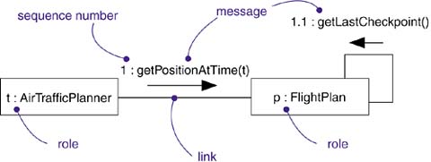
An interaction is a behavior that comprises a set of messages exchanged among objects in a set of roles within a context to accomplish a purpose. A message is a specification of a communication between objects that conveys information with the expectation that activity will ensue.
You may find an interaction wherever objects are linked to one another. You'll find interactions in the collaboration of objects that exist in the context of your system or subsystem. You will also find interactions in the context of an operation. Finally, you'll find interactions in the context of a class.
Most often, you'll find interactions in the collaboration of objects that exist in the context of your system or subsystem as a whole. For example, in a system for Web commerce, you'll find objects on the client (such as instances of the classes BookOrder and OrderForm) interacting with one another. You'll also find objects on the client (again, such as instances of BookOrder) interacting with objects on the server (such as instances of BackOrderManager). These interactions therefore not only involve localized collaborations of objects (such as the interactions surrounding OrderForm), but they may also cut across many conceptual levels of your system (such as the interactions surrounding BackOrderManager).
You'll also find interactions among objects in the implementation of an operation. The parameters of an operation, any variables local to the operation, and any objects global to the operation (but still visible to the operation) may interact with one another to carry out the algorithm of that operation's implementation. For example, the operation moveToPosition(p : Position) defined for a class in a mobile robot will involve the interaction of a parameter (p), an object global to the operation (such as the object currentPosition), and possibly several local objects (such as local variables used by the operation to calculate intermediate points in a path to the new position).
Finally, you will find interactions in the context of a class. You can use interactions to visualize, specify, construct, and document the semantics of a class. For example, to understand the meaning of a class RayTraceAgent, you might create interactions that show how the attributes of that class collaborate with one another (and with objects global to instances of the class and with parameters defined in the class's operations).
The objects that participate in an interaction are either concrete things or prototypical things. As a concrete thing, an object represents something in the real world. For example, p, an instance of the class Person, might denote a particular human. Alternately, as a prototypical thing, p might represent any instance of Person.
Note
In a collaboration, the interactors are usually prototypical things that play particular roles, not specific objects in the real world, although it is sometimes useful to describe collaborations among particular objects.
In the context of an interaction, you may find instances of classes, components, nodes, and use cases. Although abstract classes and interfaces, by definition, may not have any direct instances, you may represent instances of these things in an interaction. Such instances do not represent direct instances of the abstract class or of the interface, but may represent, respectively, indirect (or prototypical) instances of any concrete children of the abstract class of some concrete class that realizes that interface.
You can think of an object diagram as a representation of the static aspect of an interaction, setting the stage for the interaction by specifying all the objects that work together. An interaction goes further by introducing a dynamic sequence of messages that may pass along the links that connect these objects.
A link is a semantic connection among objects. In general, a link is an instance of an association. As Figure 16-2 shows, wherever a class has an association to another class, there may be a link between the instances of the two classes; wherever there is a link between two objects, one object can send a message to the other object.

A link specifies a path along which one object can dispatch a message to another (or the same) object. Most of the time it is sufficient to specify that such a path exists. If you need to be more precise about how that path exists, you can adorn the appropriate end of the link with one of the following constraints:
Specifies that the corresponding object is visible by association | |
Specifies that the corresponding object is visible because it is the dispatcher of the operation | |
Specifies that the corresponding object is visible because it is in an enclosing scope | |
Specifies that the corresponding object is visible because it is in a local scope | |
Specifies that the corresponding object is visible because it is a parameter |
Note
As an instance of an association, a link may be rendered with most of the adornments appropriate to associations, such as a name, association role name, navigation, and aggregation. Multiplicity, however, does not apply to links, since they are instances of an association.
In most models, we are more interested in prototypical objects and links within some context rather than individual objects and links. A prototypical object is called a role; a prototypical link is called a connector; the context is a collaboration or the internal structure of a classifier. The multiplicity of roles and connectors are defined relative to their enclosing context. For example, a multiplicity of 1 on a role means one object represents the role for each object that represents the context. A collaboration or internal structure can be used many times, just like a class declaration; each use is bound to a separate set of objects and links for the context, roles, and links.
Figure 16-2 shows an example. The top of the figure shows a class diagram that declares classes Person and Company and the many-to-many employee-employer association between them. The middle shows the contents of a collaboration WorkAssignment that assigns an employee to a job. It has two roles and a connector between them. The bottom shows an instance of this collaboration, in which there are objects and links bound to the roles and connectors. A concrete message in the bottom represents the prototypical message declaration in the collaboration.
Suppose you have a set of objects and a set of links that connect those objects. If that's all you have, then you have a completely static model that can be represented by an object diagram. Object diagrams model the state of a society of objects at a given moment in time and are useful when you want to visualize, specify, construct, or document a static object structure.
Suppose you want to model the changing state of a society of objects over a period of time. Think of it as taking a motion picture of a set of objects, each frame representing a successive moment in time. If these objects are not totally idle, you'll see objects passing messages to other objects, sending events, and invoking operations. In addition, at each frame you can explicitly visualize the current state and role of individual instances.
A message is the specification of a communication among objects that conveys information with the expectation that activity will ensue. The receipt of a message instance may be considered an occurrence of an event. (An occurrence is the UML name for an instance of an event.)
When you pass a message, an action usually results on its receipt. An action may result in a change in state of the target object and objects accessible from it.
In the UML, you can model several kinds of messages.
Invokes an operation on an object; an object may send a message to itself, resulting in the local invocation of an operation | |
Returns a value to the caller | |
Sends a signal to an object | |
Creates an object | |
Destroys an object; an object may commit suicide by destroying itself |
Note
You can model complex actions in the UML as well. In addition to the five basic kinds of messages listed above, you can include actions on individual objects. The UML does not specify the syntax or semantics of such actions; it is expected that tools will supply various actions languages or use the syntax of programming languages.
The UML provides a visual distinction among these kinds of messages, as Figure 16-3 shows.
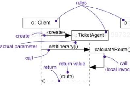
The most common kind of message you'll model is the call, in which one object invokes an operation of another (or the same) object. An object can't just call any random operation. If an object, such as c in the example above, calls the operation setItinerary on an instance of the class TicketAgent, the operation setItinerary must not only be defined for the class TicketAgent (that is, it must be declared in the class TicketAgent or one of its parents), it must also be visible to the caller c.
Note
Languages such as C++ are statically typed (although polymorphic), meaning that the legality of a call is checked at compilation time. Languages such as Smalltalk, however, are dynamically typed, meaning that you can't determine if an object can properly receive a message until execution time. In the UML, a well-formed model can in general be checked statically by a tool because, at modeling time, the developer typically knows the intent of the operation.
When an object calls an operation or sends a signal to another object, you can provide actual parameters to the message. Similarly, when an object returns control to another object, you can model the return value as well.
Messages can also correspond to the sending of signals. A signal is an object value communicated to a target object asynchronously. After sending a signal, the sending object continues its own execution. When the target object receives the signal message, it independently decides what to do about it. Usually signals trigger transitions in the state machine of the target object. Firing a transition causes the target object to execute actions and change to a new state. In an asynchronous message-passing system, communicating objects execute concurrently and independently. They share values only by passing messages, so there is no danger of conflict over shared memory.
Note
You can also qualify an operation by the class or interface in which it is declared. For example, invoking the operation register upon an instance of Student would polymorphically invoke whatever operation matches that name in the Student class hierarchy; invoking IMember::register would invoke the operation specified in the interface IMember (and realized by some suitable class, also in the Student class hierarchy).
When an object passes a message to another object (in effect, delegating some action to the receiver), the receiving object might in turn send a message to another object, which might send a message to yet a different object, and so on. This stream of messages forms a sequence. Any sequence must have a beginning; the start of every sequence is rooted in some process or thread. Furthermore, any sequence will continue as long as the process or thread that owns it lives. A nonstop system, such as you might find in real time device control, will continue to execute as long as the node it runs on is up.
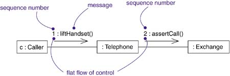
Each process and thread within a system defines a distinct flow of control, and within each flow, messages are ordered in sequence by time. To better visualize the sequence of a message, you can explicitly model the order of the message relative to the start of the sequence by prefixing the message with a sequence number set apart by a colon separator.
A communication diagram shows message flow between roles within a collaboration. Messages flow along connections of the collaboration, as in Figure 16-4.
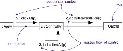
Most commonly, you can specify a procedural or nested flow of control, rendered using a filled solid arrowhead, as Figure 16-4 shows. In this case, the message findAt is specified as the first message nested in the second message of the sequence (2.1).
Less common but also possible, as Figure 16-5 shows, you can specify a flat flow of control, rendered using a stick arrowhead, to model the nonprocedural progression of control from step to step. In this case, the message assertCall is specified as the second message in the sequence.
Note
The distinction between asynchronous and procedural sequences is important in the modern concurrent computing world. To show the overall behavior of a system of concurrent objects, use asynchronous message passing. This is the most general case. When the calling object is able to make a request and wait for a respond, you can use procedural flow of control. Procedural flow of control is familiar from traditional programming languages, but keep in mind that a series of nested procedure calls results in a stack of blocked objects that are temporarily unable to do anything, so it is not very useful if they represent servers or shared resources.
When you are modeling interactions that involve multiple flows of control, it's especially important to identify the process or thread that sent a particular message. In the UML, you can distinguish one flow of control from another by prefixing a message's sequence number with the name of the process or thread that sits at the root of the sequence. For example, the expression
D5 : ejectHatch(3)
specifies that the operation ejectHatch is dispatched (with the actual argument 3) as the fifth message in the sequence rooted by the process or thread named D.
Not only can you show the actual arguments sent along with an operation or a signal in the context of an interaction, you can show the return values of a function as well. As the following expression shows, the value p is returned from the operation find, dispatched with the actual parameter "Rachelle". This is a nested sequence, dispatched as the second message nested in the third message nested in the first message of the sequence. In the same diagram, p can then be used as an actual parameter in subsequent messages.
1.3.2 : p := find("Rachelle")
Note
In the UML, you can also model more-complex forms of sequencing, such as iteration, branching, and guarded messages. In addition, to model timing constraints such as you might find in real time systems, you can associate timing marks with a sequence. Other, more exotic forms of messaging, such as balking and time out, can be modeled by defining an appropriate message stereotype.
Most of the time the objects you show participating in an interaction exist for the entire duration of the interaction. However, in some interactions objects may be created (specified by a create message) and destroyed (specified by a destroy message). The same is true of links: The relationships among objects may come and go. To specify if an object or link enters and/or leaves during an interaction, you can attach a note to its role within a communication diagram.
During an interaction, an object typically changes the values of its attributes, its state, or its roles. You can represent the modification of an object in a sequence diagram by showing the state or the values on the lifeline.
Within a sequence diagram, the lifetime, creation, and destruction of objects or roles are explicitly shown by the vertical extent of their lifelines. Within a communication diagram, creation and destruction must be indicated using notes. Use sequence diagrams if object lifetimes are important to show.
When you model an interaction, you typically include both roles (each one representing objects that appear in an instance of the interaction) and messages (each one representing the communication between objects, with some resulting action).
You can visualize those roles and messages involved in an interaction in two ways: by emphasizing the time ordering of its messages, and by emphasizing the structural organization of the roles that send and receive messages. In the UML, the first kind of representation is called a sequence diagram; the second kind of representation is called a communication diagram. Both sequence diagrams and communication diagrams are kinds of interaction diagrams. (UML also has a more specialized kind of interaction diagram called a timing diagram, which shows the exact times at which messages are exchanged by roles. This diagram is not covered in this book. See the UML Reference Manual for more information.)
Sequence diagrams and communication diagrams are similar, meaning that you can take one and transform it into the other, although they often show different information, so it may not be so useful to go back and forth. There are some visual differences. First, sequence diagrams permit you to model the lifeline of an object. An object's lifeline represents the existence of the object at a particular time, possibly covering the object's creation and destruction. Second, communication diagrams permit you to model the structural links that may exist among the objects in an interaction.
The most common purpose for which you'll use interactions is to model the flow of control that characterizes the behavior of a system as a whole, including use cases, patterns, mechanisms, and frameworks, or the behavior of a class or an individual operation. Whereas classes, interfaces, components, nodes, and their relationships model the static aspects of your system, interactions model its dynamic aspects.
When you model an interaction, you essentially build a storyboard of the actions that take place among a set of objects. Techniques such as CRC cards are particularly useful in helping you to discover and think about such interactions.
To model a flow of control,
Set the context for the interaction, whether it is the system as a whole, a class, or an individual operation.
Set the stage for the interaction by identifying which objects play a role; set their initial properties, including their attribute values, state, and role. Name the roles.
If your model emphasizes the structural organization of these objects, identify the links that connect them, relevant to the paths of communication that take place in this interaction. Specify the nature of the links using the UML's standard stereotypes and constraints, as necessary.
In time order, specify the messages that pass from object to object. As necessary, distinguish the different kinds of messages; include parameters and return values to convey the necessary detail of this interaction.
Also to convey the necessary detail of this interaction, adorn each object at every moment in time with its state and role.
For example, Figure 16-6 shows a set of roles that interact in the context of a publish and subscribe mechanism (an instance of the observer design pattern). This figure includes three roles: p (a StockQuotePublisher), s1, and s2 (both instances of StockQuoteSubscriber). This figure is an example of a sequence diagram, which emphasizes the time order of messages.
Figure 16-7 is semantically equivalent to the previous one, but it is drawn as a communication diagram, which emphasizes the structural organization of the objects. This figure shows the same flow of control, but it also provides a visualization of the links among these objects.

When you model interactions in the UML, remember that every interaction represents the dynamic aspect of a society of objects. A well-structured interaction
Is simple and should encompass only those objects that work together to carry out some behavior bigger than the sum of all these elements.
Has a clear context and may represent the interaction of objects in the context of an operation, a class, or the system as a whole.
Is efficient and should carry out its behavior with an optimal balance of time and resources.
Is adaptable, and elements of an interaction that are likely to change should be isolated so that they can be easily modified.
Is understandable and should be straightforward, involving no hacks, hidden side effects, or obscure semantics.
When you draw an interaction in the UML,
Choose an emphasis for the interaction. You can emphasize either the ordering of messages over time or the sequencing of messages in the context of some structural organization of objects. You can't do both at the same time.
Note that events in separate subsequences are only partially ordered. Each subsequence is ordered but the relative times of events in different subsequences is not fixed.
Show only those properties of each object (such as attribute values, role, and state) that are important to understanding the interaction in its context.
Show only those properties of each message (such as its parameters, concurrency semantics, and return value) that are important to understanding the interaction in its context.