In this chapter
Collaborations, realizations, and interactions
Reifying interactions
In the context of a systems architecture, a collaboration allows you to name a conceptual chunk that encompasses both static and dynamic aspects. A collaboration names a society of classes, interfaces, and other elements that work together to provide some cooperative behavior that's bigger than the sum of all its parts.
You use collaborations to specify the realization of use cases and operations, and to model the architecturally significant mechanisms of your system.
Think about the most beautiful building you've even seen—perhaps the Taj Mahal or Notre Dame. Both structures exhibit a quality that's hard to name. In many ways, both structures are architecturally simple, yet they are also profoundly deep. In each, you can immediately recognize a consistent symmetry. Look harder, and you'll see details that are themselves beautiful and that work together to produce a beauty and functionality that's greater than the individual parts.
Now think about the ugliest building you've even seen—perhaps your local fast food outlet. You'll find a visual cacophony of architectural styles—a touch of modernism combined with a Georgian roof line, all decorated in a jarring fashion, with bold colors that assault the eye. Usually these buildings are pure manipulation, with narrow function and hardly any form.
What's the difference between these two kinds of civil architecture? First, in buildings of quality, you'll find a harmony of design that's lacking in the others. Quality architecture uses a small set of architectural styles applied in a consistent fashion. For example, the Taj Mahal uses complex, symmetrical, and balanced geometric elements throughout. Second, in buildings of quality, you'll find common patterns that transcend the building's individual elements. For example, in Notre Dame, certain walls are load bearing and serve to support the cathedral's dome. Yet some of these same walls, along with other architectural details, serve as part of the building's system for diverting water and waste.
So it is with software. A quality software-intensive system is not only functionally sound, but it also exhibits a harmony and balance of design that makes it resilient to change. This harmony and balance most often come from the fact that all well-structured object-oriented systems are full of patterns. Look at any quality object-oriented system and you'll see elements that work together in common ways to provide some cooperative behavior that's bigger than the sum of all its parts. In a well-structured system, many of the elements, in various combinations, will participate in different mechanisms.
Note
A pattern provides a good solution to a common problem in some context. In any well-structured system, you'll find a spectrum of patterns, including idioms (representing common ways of programming), mechanisms (design patterns that represent conceptual chunks of a system's architecture), and frameworks (architectural patterns that provide extensible templates for applications within a domain).
In the UML, you model mechanisms using collaborations. A collaboration gives a name to the interacting building blocks of your system, encompassing both structural and behavioral elements. For example, you might have a distributed management information system whose databases are spread across several nodes. From the user's perspective, updating information looks atomic; from the inside perspective, it's not so simple, because such an action has to touch multiple machines. To give the illusion of simplicity, you'd want to devise a transaction mechanism with which a client could name what looks like a single, atomic transaction, even across various databases. Such a mechanism would span multiple classes working together to carry out a transaction. Many of these classes would be involved in other mechanisms as well, such as mechanisms for making information persistent. This collection of classes (the structural part), together with their interactions (the behavioral part), forms a mechanism, which, in the UML, you can represent as a collaboration.
Collaborations not only name a system's mechanisms, they also serve as the realization of use cases and operations.
The UML provides a graphical representation for collaborations, as Figure 28-1 shows. This notation permits you to visualize the structural and behavioral building blocks of a system, especially as they may overlap the classes, interfaces, and other elements of the system.
Note
This notation lets you visualize a collaboration from the outside as one chunk. What's often more interesting is what's inside this notation. Zoom into a collaboration and you'll be led to other diagrams—most notably, class diagrams (for the collaboration's structural part) and interaction diagrams (for the collaboration's behavioral part).
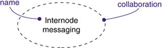
A collaboration is a society of classes, interfaces, and other elements that work together to provide some cooperative behavior that's bigger than the sum of all its parts. A collaboration is also the specification of how an element, such as a classifier (including a class, interface, component, node, or use case) or an operation, is realized by a set of classifiers and associations playing specific roles used in a specific way. Graphically, a collaboration is rendered as an ellipse with dashed lines.
Every collaboration must have a name that distinguishes it from other collaborations. A name is a textual string. That name alone is known as a simple name; a qualified name is the collaboration name prefixed by the name of the package in which that collaboration lives. Typically, a collaboration is drawn showing only its name, as in the previous figure.
Note
A collaboration name may be text consisting of any number of letters, numbers, and certain punctuation marks (except for marks such as the colon, which is used to separate a collaboration name and the name of its enclosing package) and may continue over several lines. In practice, collaboration names are short nouns or noun phrases drawn from the vocabulary of the system you are modeling. Typically, you capitalize the first letter of a collaboration name, as in Transaction or Chain of responsibility.
Collaborations have two aspects: a structural part that specifies the classes, interfaces, and other elements that work together to carry out the named collaboration; and a behavioral part that specifies the dynamics of how those elements interact.
The structural part of a collaboration is an internal (composite) structure that may include any combination of classifiers, such as classes, interfaces, components, and nodes. Within a collaboration, these classifiers may be organized using all the usual UML relationships, including associations, generalizations, and dependencies. In fact, the structural aspects of a collaboration may use the full range of the UML's structural modeling facilities.
However, unlike a structured class, a collaboration does not own its structural elements. Rather, a collaboration simply references or uses the classes, interfaces, components, nodes, and other structural elements that are declared elsewhere. That's why a collaboration names a conceptual chunk—not a physical chunk—of a system's architecture. A collaboration may cut across many levels of a system. Furthermore, the same element may appear in more than one collaboration (and some elements will not be named as part of any collaboration at all).
For example, given a Web-based retail system described by a dozen or so use cases (such as Purchase Items, Return Items, and Query Order), each use case will be realized by a single collaboration. In addition, each of these collaborations will share some of the same structural elements (such as the classes Customer and Order), but they will be organized in different ways. You'll also find collaborations deeper inside the system, which represent architecturally significant mechanisms. For example, in this same retail system, you might have a collaboration called Internode messaging that specifies the details of secure messaging among nodes.
Given a collaboration that names a conceptual chunk of a system, you can zoom inside that collaboration to expose the structural details of its parts. For example, Figure 28-2 illustrates how zooming inside the collaboration Internode messaging might reveal the following set of classes, rendered in a class diagram.

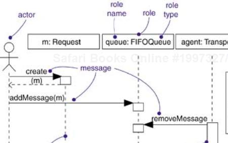
Whereas the structural part of a collaboration is typically rendered using a composite structure diagram, the behavioral part of a collaboration is typically rendered using an interaction diagram. An interaction diagram specifies an interaction that represents a behavior comprised of a set of messages that are exchanged among a set of objects within a context to accomplish a specific purpose. An interaction's context is provided by its enclosing collaboration, which establishes the classes, interfaces, components, nodes, and other structural elements whose instances may participate in that interaction.
The behavioral part of a collaboration may be specified by one or more interaction diagrams. If you want to emphasize the time ordering of messages, use a sequence diagram. If you want to emphasize the structural relationships among these objects as they collaborate, use a collaboration diagram. Either diagram is appropriate because, for most purposes, they are semantically equivalent.
This means that when you model a society of classes by naming their interaction as a collaboration, you can zoom inside that collaboration to expose the details of their behavior. For example, zooming inside the collaboration named Internode messaging might reveal the interaction diagram shown in Figure 28-3.
Note
The behavioral parts of a collaboration must be consistent with its structural parts. This means that the roles found in a collaboration's interactions must match the roles found in its internal structure. Similarly, the messages named in an interaction must relate to operations visible in the collaboration's structural part. You can have more than one interaction associated with a collaboration, each of which may show a different—but consistent—aspect of its behavior.
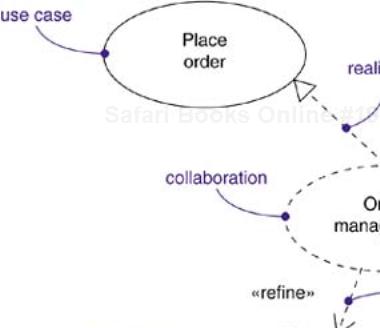
The heart of a system's architecture is found in its collaborations, because the mechanisms that shape a system represent significant design decisions. All well-structured object-oriented systems are composed of a modestly sized and regular set of such collaborations, so it's important for you to organize your collaborations well. There are two kinds of relationships concerning collaborations that you'll need to consider.
First, there is the relationship between a collaboration and the thing it realizes. A collaboration may realize either a classifier or an operation, which means that the collaboration specifies the structural and behavioral realization of that classifier or operation. For example, a use case (which names a set of sequences of actions that a system performs) may be realized by a collaboration. That use case, including its associated actors and neighboring use cases, provides a context for the collaboration. Similarly, an operation (which names the implementation of a service) may be realized by a collaboration. That operation, including its parameters and possible return value, also provides a context for the collaboration. The relationship between a use case or an operation and the collaboration that realizes it is modeled as a realization relationship.
Note
A collaboration may realize any kind of classifier, including classes, use cases, interfaces, and components. A collaboration that models a mechanism of the system may also stand alone, therefore its context is the system as a whole.
Second, there is the relationship among collaborations. Collaborations may refine other collaborations, and you also model this relationship as a refinement. The refinement relationships among collaborations typically mirror the refinement relationships among the use cases they represent.
Figure 28-4 illustrates these two kinds of relationships.
Objects represent single individuals in a situation or execution. They are useful within concrete examples, but most of the time we want to show general parts within some context. A part within a context is called a role. Perhaps the most important thing for which you'll use roles is to model the dynamic interactions. When you model such interactions, you are generally not modeling concrete instances that exist in the real world. Instead, you are modeling roles within a reusable pattern, within which the roles are essentially proxies or stand-ins for objects that will appear within individual instances of the pattern. For example, if you want to model the ways objects in a windowing application react to a mouse event, you'd draw an interaction diagram containing roles whose types include windows, events, and handlers.
To model roles,
Identify a context within which several objects interact.
Identify those roles necessary and sufficient to visualize, specify, construct, or document the context you are modeling.
Render these roles in the UML as roles in a structured context. Where possible, give each role a name. If there is no meaningful name for the role, render it as an anonymous role.
Expose the properties of each role necessary and sufficient to model your context.
Render these roles and their relationships in an interaction diagram or a class diagram.
Note
The semantic difference between concrete objects and roles is subtle but not difficult. To be precise, a UML role is a predefined part of a structured classifier, such as a structured class or a collaboration. A role is not an object, but a description; a role is bound to a value within each instance of a structured classifier. A role therefore corresponds to many possible values, just as an attribute does. Concrete objects appear in specific examples, such as object diagrams, component diagrams, and deployment diagrams. Roles appear in generic descriptions as interaction diagrams and activity diagrams.
Figure 28-5 shows an interaction diagram illustrating a partial scenario for initiating a phone call in the context of a switch. There are four roles: a (a CallingAgent), c (a Connection), and t1 and t2 (both instances of Terminal). All four of these roles represent conceptual proxies for concrete objects that may exist in the real world.

Note
This example is a collaboration, which represents a society of objects and other elements that work together to provide some cooperative behavior that's bigger than the sum of all the elements. Collaborations have two aspects—one structural (representing the classifier roles and their relationships) and one dynamic (representing the interactions among those prototypical instances).
One of the purposes for which you'll use collaborations is to model the realization of a use case. You'll typically drive the analysis of your system by identifying your system's use cases, but when you finally turn to implementation, you'll need to realize these use cases with concrete structures and behaviors. In general, every use case should be realized by one or more collaborations. For the system as a whole, the classifiers involved in a given collaboration that is linked to a use case will participate in other collaborations as well. In this way, the structural contents of collaborations tend to overlap one another.
To model the realization of a use case,
Identify those structural elements necessary and sufficient to carry out the semantics of the use case.
Capture the organization of these structural elements in class diagrams.
Consider the individual scenarios that represent this use case. Each scenario represents a specific path through the use case.
Capture the dynamics of these scenarios in interaction diagrams. Use sequence diagrams if you want to emphasize the time ordering of messages. Use communication diagrams if you want to emphasize the structural relationships among these objects as they collaborate.
Organize these structural and behavioral elements as a collaboration that you can connect to the use case via realization.
For example, Figure 28-6 shows a set of use cases drawn from a credit card validation system, including the primary use cases Place order and Generate bill, together with two other subordinate use cases, Detect card fraud and Validate transaction. Although most of the time you won't need to model this relationship explicitly (but will leave it up to your tools), this figure explicitly models the realization of Place order by the collaboration Order management. In turn, this collaboration can be further expanded into its structural and behavioral aspects, leading you to class diagrams and interaction diagrams. It is through the realization relationship that you connect a use case to its scenarios.
In most cases, you won't need to model the relationship between a use case and the collaboration that realizes it explicitly. Instead, you'll tend to leave that in the backplane of your model. Then let tools use that connection to help you navigate between a use case and its realization.
Another purpose for which you'll use collaborations is to model the realization of an operation. In many cases, you can specify the realization of an operation by going straight to code. However, for those operations that require the collaboration of a number of objects, it's better to model their implementation via collaborations before you dive into code.
The parameters, return value, and objects local to an operation provide the context for its realization. Therefore, these elements are visible to the structural aspect of the collaboration that realizes the operation, just as actors are visible to the structural aspect of a collaboration that realizes a use case. You can model the relationship among these parts using a composite structure diagram that specifies the structural part of a collaboration.
To model the implementation of an operation,
Identify the parameters, return value, and other objects visible to the operation. These become roles of the collaboration.
If the operation is trivial, represent its implementation directly in code, which you can keep in the backplane of your model, or explicitly visualize it in a note.
If the operation is algorithmically intensive, model its realization using an activity diagram.
If the operation is complex or otherwise requires some detailed design work, represent its implementation as a collaboration. You can further expand the structural and behavioral parts of this collaboration using class and interaction diagrams, respectively.
For example, Figure 28-7 shows the active class RenderFrame with three of its operations exposed. The function progress is simple enough to be implemented directly in code, as specified in the attached note. However, the operation render is much more complicated, so its implementation is realized by the collaboration Ray trace. Although not shown here, you could zoom inside the collaboration to see its structural and behavioral aspects.
Note
You can also model an operation using activity diagrams. Activity diagrams are essentially flowcharts. So for those algorithmically intensive operations that you want to model explicitly, activity diagrams are usually the best choice. However, if your operation requires the participation of many objects, you'll want to use collaborations, because they let you model the structural, as well as behavioral, aspects of an operation.
In all well-structured object-oriented systems, you'll find a spectrum of patterns. At one end, you'll find idioms that represent patterns of use of the implementation language. At the other end, you'll find architectural patterns and frameworks that shape the system as a whole and impose a particular style. In the middle, you'll find mechanisms that represent common design patterns by which the things in the system interact with one another in common ways. You can represent a mechanism in the UML as a collaboration.
Mechanisms are collaborations that stand alone; their context is not a single use case or an operation but, rather, the system as a whole. Any element visible in that part of the system is a candidate for participation in a mechanism.
Mechanisms such as these represent architecturally significant design decisions and should not be treated lightly. Typically, your system's architect will devise its mechanisms, and you'll evolve these mechanisms with each new release. At the end, you'll find your system simple (because these mechanisms reify common interactions), understandable (because you can approach the system from its mechanisms), and resilient (by tuning each mechanism, you tune the system as a whole).
To model a mechanism,
Identify the major mechanisms that shape your system's architecture. These mechanisms are driven by the overall architectural style you choose to impose on your implementation, along with the style appropriate to your problem domain.
Represent each of these mechanisms as a collaboration.
Expand on the structural and behavioral part of each collaboration. Look for sharing, where possible.
Validate these mechanisms early in the development lifecycle (they are of strategic importance), but evolve them with each new release, as you learn more about the details of your implementation.
When you model collaborations in the UML, remember that every collaboration should represent either the realization of a use case or operation or should stand alone as a mechanism of the system. A well-structured collaboration
Consists of both structural and behavioral aspects.
Provides a crisp abstraction of some identifiable interaction in the system.
Is rarely completely independent, but will overlap with the structural elements of other collaborations.
Is understandable and simple.
When you draw a collaboration in the UML,
Explicitly render a collaboration only when it's necessary to understand its relationship to other collaborations, classifiers, operations, or the system as a whole. Otherwise, use collaborations, but keep them in the backplane.
Organize collaborations according to the classifier or operation they represent, or in packages associated with the system as a whole.