In this chapter
Wiring subcomponents together
A component is a logical, replaceable part of a system that conforms to and provides the realization of a set of interfaces.
Good components define crisp abstractions with well-defined interfaces, making it possible to easily replace older components with newer, compatible ones.
Interfaces bridge your logical and design models. For example, you may specify an interface for a class in a logical model, and that same interface will carry over to some design component that realizes it.
Interfaces allow you to build the implementation of a component using smaller components by wiring ports on the components together.
When you are building a house, you may choose to install a home entertainment system. It is possible to buy a single unit that includes everything: television screen, tuner, VCR, DVD player, and speakers. Such a system is easy to install and works great if it meets your needs. A one-piece unit is not very flexible, however. You have to take the combination of features that the manufacturer provides. You probably won't be able to get high-quality speakers. If you want to install a new high-definition television screen, you have to throw away the entire unit and replace it, including the VCR and DVD player that may still be working fine. If you have a collection of records (some of you readers may remember what those are), you are out of luck.
A more flexible approach is to build your entertainment system out of individual components, each focused on a single functionality. A monitor displays the picture; individual speakers play the sound, and they can be placed wherever your room and ears allow; the tuner, VCR, and DVD player are each separate units, their capabilities adjusted to your videophile requirements and your budget. Instead of being locked together in a rigid fashion, you place each component where you want and hook them together with cables. Each cable has a specific kind of plug that fits into a matching port on a component, so you can't plug a speaker wire into a video output. You can hook up your old turntable if you want. When you want to upgrade your system, you can replace one component at a time without trashing the entire system and starting over. Components provide more flexibility and permit you to obtain higher quality, if you want it and can afford it.
Software is similar. You can construct an application as a large, monolithic unit, but it will be rigid and difficult to modify as needs change. In addition, you can't take advantage of existing capabilities. Even if an existing system has much of the functionality you need, it may also have a lot of other parts that you don't want, and they are difficult or impossible to remove. The solution for software systems is the same as for electronics systems: Build them from well defined components that can be wired together flexibly and replaced individually as requirements change.
An interface is a collection of operations that specify a service that is provided by or requested from a class or component.
A component is a replaceable part of a system that conforms to and provides the realization of a set of interfaces.
A port is a specific window into an encapsulated component accepting messages to and from the component conforming to specified interfaces.
Internal structure is the implementation of a component by means of a set of parts that are connected together in a specific way.
A part is the specification of a role that composes part of the implementation of a component. In an instance of the component, there is an instance corresponding to the part.
A connector is a communication relationship between two parts or ports within the context of a component.
An interface is a collection of operations that are used to specify a service of a class or a component. The relationship between component and interface is important. All the most common component-based operating system facilities (such as COM+, CORBA, and Enterprise Java Beans) use interfaces as the glue that binds components together.
To construct a system based on components, you decompose your system by specifying interfaces that represent the major seams in the system. You then provide components that realize the interfaces, along with other components that access the services through their interfaces. This mechanism permits you to deploy a system whose services are somewhat location-independent and, as discussed in the next section, replaceable.
An interface that a component realizes is called a provided interface, meaning an interface that the component provides as a service to other components. A component may declare many provided interfaces. The interface that a component uses is called a required interface, meaning an interface that the component conforms to when requesting services from other components. A component may conform to many required interfaces. Also, a component may both provide and require interfaces.
As Figure 15-1 indicates, a component is shown as a rectangle with a small two-pronged icon in its upper right corner. The name of the component appears in the rectangle. A component can have attributes and operations, but these are often elided in diagrams. A component can show a network of internal structure, as described later in this chapter.

You can show the relationship between a component and its interfaces in one of two ways. The first (and most common) style renders the interface in its elided, iconic form. A provided interface is shown as a circle attached to the component by a line (a “lollipop”). A required interface is shown as a semicircle attached to the component by a line (a “socket”). In both cases, the name of the interface is placed next to the symbol. The second style renders the interface in its expanded form, perhaps revealing its operations. The component that realizes the interface is connected to the interface using a full realization relationship. The component that accesses the services of the other component through the interface is connected to the interface using a dependency relationship.
A given interface may be provided by one component and required by another. The fact that this interface lies between the two components breaks the direct dependency between the components. A component that uses a given interface will function properly no matter what component realizes that interface. Of course, a component can be used in a context if and only if all its required interfaces are realized as provided interfaces of other components.
The basic intent of every component-based operating system facility is to permit the assembly of systems from binary replaceable artifacts. This means that you can design a system using components and then implement those components using artifacts. You can then evolve that system by adding new components and replacing old ones, without rebuilding the system. Interfaces are the key to making this happen. In the executable system, you can use any artifacts that implement a component conforming to or providing that interface. You can extend the system by making the components provide new services through other interfaces, which, in turn, other components can discover and use. These semantics explain the intent behind the definition of components in the UML. A component conforms to and provides the realization of a set of interfaces and enables substitutability both in the logical design and in the physical implementation based on it.
A component is replaceable. A component is substitutable—it is possible to replace a component with another that conforms to the same interfaces. At design time, you choose a different component. Typically, the mechanism of inserting or replacing an artifact in a run time system is transparent to the component user and is enabled by object models (such as COM+ and Enterprise Java Beans) that require little or no intervening transformation or by tools that automate the mechanism.
A component is part of a system. A component rarely stands alone. Rather, a given component collaborates with other components and in so doing exists in the architectural or technology context in which it is intended to be used. A component is logically and physically cohesive and thus denotes a meaningful structural and/or behavioral chunk of a larger system. A component may be reused across many systems. Therefore, a component represents a fundamental building block on which systems can be designed and composed. This definition is recursive—a system at one level of abstraction may simply be a component at a higher level of abstraction.
Finally, as discussed in the previous section, a component conforms to and provides the realization of a set of interfaces.
You can organize components by grouping them in packages in the same manner in which you organize classes.
You can also organize components by specifying dependency, generalization, association (including aggregation), and realization relationships among them.
Components can be built from other components. See the discussion on internal structure later in this chapter.
Interfaces are useful in declaring the overall behavior of a component, but they have no individual identity; the implementation of the component must merely ensure that all the operations in all of the provided interfaces are implemented. To have greater control over the implementation, ports can be used.
A port is an explicit window into an encapsulated component. In an encapsulated component, all of the interactions into and out of the component pass through ports. The externally visible behavior of the component is the sum of its ports, no more and no less. In addition, a port has identity. Another component can communicate with the component through a specific port. The communications are described completely by the interfaces that the port supports, even if the component supports other interfaces. In the implementation, the internal parts of the component may interact through a specific external port, so that each part can be independent of the requirements of the other parts. Ports permit the interfaces of a component to be divided into discrete packets and used independently. The encapsulation and independence provided by ports permit a much greater degree of encapsulation and substitutability.
A port is shown as a small square straddling the border of a component—it represents a hole through the encapsulation boundary of the component. Both provided and required interfaces may be attached to the port symbol. A provided interface represents a service that can be requested through that port. A required interface represents a service that the port needs to obtain from some other component. Each port has a name so that it can be uniquely identified given the component and the port name. The port name can be used by internal parts of the component to identify the port through which to send and receive messages. The component name and port name together uniquely identify a specific port in a specific component for use by other components.
Ports are part of a component. Instances of ports are created and destroyed along with the instance of the component to which they belong. Ports may also have multiplicity; this indicates the possible number of instances of a particular port within an instance of the component. Each port on a component instance has an array of port instances. Although the port instances in an array all satisfy the same interface and accept the same kinds of requests, they may have different states and data values. For example, each instance in an array might have a different priority level, with the higher-priority port instances being served first.
Figure 15-2 shows the model of a Ticket Seller component with ports. Each port has a name and, optionally, a type to tell what kind of a port it is. The component has ports for ticket sales, attractions, and credit card charging.
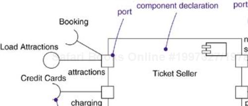
There are two ports for ticket sales, one for normal customers and one for priority customers. They both have the same provided interface of type Ticket Sales. The credit card processing port has a required interface; any component that provides the specified services can satisfy it. The attractions port has both provided and required interfaces. Using the Load Attractions interface, a theater can enter shows and other attractions into the ticket database for sale. Using the Booking interface, the ticket seller component can query the theaters for the availability of tickets and actually buy the tickets.
A component can be implemented as a single piece of code, but in larger systems it is desirable to be able to build large components using smaller components as building blocks. The internal structure of a component is the parts that compose the implementation of the component together with the connections among them. In many cases, the internal parts can be instances of smaller components that are wired together statically through ports to provide the necessary behavior without the need for the modeler to specify extra logic.
A part is a unit of the implementation of a component. A part has a name and a type. In an instance of the component, there is one or more instance corresponding to each part having the type specified by the part. A part has a multiplicity within its component. If the multiplicity of the part is greater than one, there may be more than one part instance in a given component instance. If the multiplicity is something other than a single integer, the number of part instances may vary from one instance of the component to another. A component instance is created with the minimum number of parts; additional parts can be added later. An attribute of a class is a kind of part: it has a type and a multiplicity, and each instance of the class has one or more instance of the given type.
Figure 15-3 shows a compiler component built from four kinds of parts. There is a lexical analyzer, a parser, a code generator, and one to three optimizers. More complete versions of the compiler can be configured with different levels of optimization; within a given version, the appropriate optimizer can be selected at run time.

Note that a part is not the same as a class. Each part is potentially distinguishable by its name, just like each attribute in a class is distinguishable. There can be more than one part of the same type, but you can tell them apart by their names, and presumably they have distinct functions within the component. For example, in Figure 15-4 an Air Ticket Sales component might have separate Sales parts for frequent fliers and for regular customers; they both work the same, but the frequent-flier part is available only to special customers and involves less chance of waiting in line and may provide additional perks. Because these components have the same type, they must have names to distinguish them. The other two components of types SeatAssignment and InventoryManagement do not require names because there is only one of each type within the Air Ticket Sales component.
If the parts are components with ports, you can wire them together through their ports. The rule is simple: Two ports can be connected together if one provides a given interface and the other requires the interface. Connecting the ports means that the requiring port will invoke the providing port to obtain services. The advantage of ports and interfaces is that nothing else needs to be known; if the interfaces are compatible, the ports can be connected. A tool could automatically generate calling code from one component to another. They can also be reconnected to other components that provide the same interfaces, if new components become available. A wire between two ports is called a connector. In an instance of the overall component, it represents a link or a transient link. A link is an instance of an ordinary association. A transient link represents a usage relationship between two components. Instead of an ordinary association, it might be supplied by a procedure parameter or a local variable that serves as the target of an operation. The advantage of ports and interfaces is that the two components don't have to know about each other at design time, as long as their interfaces are compatible.
You can show connectors in two ways (Figure 15-5). If two components are explicitly wired together, either directly or through ports, just draw a line between them or their ports. On the other hand, if two components are connected because they have compatible interfaces, you can use a ball-and-socket notation to show that there is no inherent relationship between the components, although they are connected inside this component. You could substitute some other component that satisfies the interface.

You can also wire internal ports to external ports of the overall component. This is called a delegation connector, because messages on the external port are delegated to the internal port. This is shown by an arrow from an internal port to an external port. You can think of this in two ways, whichever you prefer: In the first approach, the internal port is the same as the external port; it has been moved to the boundary and allowed to peek through. In the second approach, any message to the external port is transmitted immediately to the internal port, and vice versa. It really doesn't matter; the behavior is the same in either case.
Figure 15-5 shows an example with internal ports and different kinds of connectors. External requests on the OrderEntry port are delegated to the internal port of the OrderTaking subcomponent. This component in turn sends its output to its OrderHandoff port. This port is connected by a ball-and-socket symbol to the OrderHandling subcomponent. This kind of connection implies that there is no special knowledge between the two components; the output could be connected to any component that obeys the OrderHandoff interface. The OrderHandling component communicates with the Inventory component to find the items in stock. This is shown as a direct connector; because no interfaces are shown, this tends to suggest that the connection is more tightly coupled. Once the items are found in stock, the OrderHandling component accesses an external Credit service; this is shown by the delegation connector to the external port called changing. Once the external credit service responds, the OrderHandling component communicates with a different port ShipItems on the Inventory component to prepare the order for shipment. The Inventory component accesses an external Fulfillment service to actually perform the shipment.
Note that the component diagram shows the structure and potential message paths of the component. The component diagram itself does not show the sequencing of messages through the component. Sequencing and other kinds of dynamic information can be shown using interaction diagrams.
Note
Internal structure, including ports, parts, and connectors, can be used as the implementation of any class, not just components. There really isn't much of a semantic distinction between classes and components. It is often useful, however, to use the convention that components are used for encapsulated concepts with internal structure, particularly those concepts that do not map directly to a single class in the implementation.
A structured class can be used to model data structures in which the parts have contextual connections that apply only within the class. Ordinary attributes or associations can define composite parts of a class, but the parts cannot be related to each other on a plain class diagram. A class whose internal structure is shown with parts and connectors avoids this problem.
To model a structured class,
Identify the internal parts of the class and their types.
Give each part a name that indicates its purpose in the structured class, not its generic type.
Draw connectors between parts that communicate or have contextual relationships.
Feel free to use other structured classes as the types of parts, but remember that you can't make connections to parts inside another structured class; connect to its external ports.
Figure 15-6 shows the design of the structured class TicketOrder. This class has four parts and one ordinary attribute, price. The customer is a Person object. The customer may or may not have a priority status, so the priority part is shown with multiplicity 0..1; the connector from customer to priority also has the same multiplicity. There are one or more seats reserved; seat has a multiplicity value. It is unnecessary to show a connector from customer to seats because they are in the same structured class anyway. Notice that Attraction is drawn with a dashed border. This means that the part is a reference to an object that is not owned by the structured class. The reference is created and destroyed with an instance of the TicketOrder class, but instances of Attraction are independent of the TicketOrder class. The seat part is connected to the attraction reference because the order may include seats for more than one attraction, and each seat reservation must be connected to a specific attraction. We see from the multiplicity on the connector that each Seat reservation is connected to exactly one Attraction object.
If you are a developer who's assembling a system from component parts, you'll often want to see the application programming interfaces (APIs) that you use to glue these parts together. APIs represent the programmatic seams in your system, which you can model using interfaces and components.
An API is essentially an interface that is realized by one or more components. As a developer, you'll really care only about the interface itself; which component realizes an interface's operations is not relevant as long as some component realizes it. From a system configuration management perspective, though, these realizations are important because you need to ensure that when you publish an API, there's some realization available that carries out the API's obligations. Fortunately, with the UML, you can model both perspectives.
The operations associated with any semantically rich API will be fairly extensive, so most of the time you won't need to visualize all these operations at once. Instead, you'll tend to keep the operations in the backplane of your models and use interfaces as handles with which you can find these sets of operations. If you want to construct executable systems against these APIs, you will need to add enough detail so that your development tools can compile against the properties of your interfaces. Along with the signatures of each operation, you'll probably also want to include uses cases that explain how to use each interface.
Identify the seams in your system and model each seam as an interface, collecting the attributes and operations that form this edge.
Expose only those properties of the interface that are important to visualize in the given context; otherwise, hide these properties, keeping them in the interface's specification for reference, as necessary.
Model the realization of each API only insofar as it is important to show the configuration of a specific implementation.
Figure 15-7 exposes the APIs of an animation component. You'll see four interfaces that form the API: IApplication, IModels, IRendering, and IScripts. Other components can use one or more of these interfaces as needed.
Components allow you to encapsulate the parts of your system to reduce dependencies, make them explicit, and enhance replaceability and flexibility when the system must be changed in the future. A good component:
Encapsulates a service that has a well-defined interface and boundary.
Has enough internal structure to be worth describing.
Does not combine unrelated functionality into a single unit.
Organizes its external behavior using a few interfaces and ports.
Interacts only through declared ports.
If you choose to show the implementation of a component using nested subcomponents:
Use a moderate number of subcomponents. If there are too many to show comfortably on one page, use additional levels of decomposition in some of the subcomponents.
Ensure that the subcomponents interact only through defined ports and connectors.
Determine which subcomponents interact directly with the external world and model them with delegation connectors.
When you draw a component in the UML:
Give it a name that clearly indicates its purpose. Name interfaces in the same way.
Name subcomponents and ports if their meaning is not clear from their types or if there are multiple parts of the same type.
Hide unnecessary detail. You don't have to show every detail of the implementation on the component diagram.
Show the dynamics of a component using interaction diagrams.