
Chapter 13: Robot Joint Setup and Skinning in Blender
In the previous chapter, we completed a very simple skeleton for the Alien Plant. Now, we can move on to something a bit more complex. The robot character has more independently moving parts, and it also has an arm that will need a better control system than just rotating joints when we come to the rigging and animation parts later in this book. Creating the skeleton for our robot will be very similar to what we did in the previous chapter; however, here, we need to pay a bit more attention to our joint orientations and local axes of our bones/joints. This will be explained in more detail later in this chapter.
The robot is a rigid metal body, so the way we will do the skinning will be a bit different from the previous chapter, but in some ways much simpler.
In this chapter, we will cover the following topics:
- Creating a skeleton for the robot
- Checking and editing the local joint orientations of the joints
- Skinning the robot to the skeleton in a rigid way
Technical requirements
You need to have Blender installed, which can you get for free at https://www.blender.org/ (at the time of writing). The Blender version that's being used in this chapter is 3.1.2, but some older and newer versions will also work.
You also need to have a basic understanding of how to navigate the 3D user interface. If you've skipped ahead, then please go back to Chapter 1, An Introduction to Blender's 3D Modeling and Sculpting Tools. If you want further tutorials on how to use Blender, then https://www.blender.org/support/tutorials/ is a great resource.
Finally, you should have completed Chapter 12, Alien Plant Skinning in Blender.
The files related to this chapter are placed at https://github.com/PacktPublishing/Unreal-Engine-5-Character-Creation-Animation-and-Cinematics/tree/main/Chapter13
Creating a skeleton for the robot
To create a skeleton for the robot, we will begin where we began in the previous chapter when we worked with the Alien Plant model.
Opening, positioning, and scaling the robot
Open the Blender file of the robot you created in Chapter 2, Modeling a Robot Drone Character. If you didn't do this, open the completed robot model file that accompanies this book: https://github.com/PacktPublishing/Unreal-Engine-5-Character-Creation-Animation-and-Cinematics/blob/main/Chapter13/RobotDrone_Blender_File.blend. Check that the scale and positioning of the model are correct and that the model is in the center of the scene. We want a model that is around 40-50 cm tall for our final scene, so use the Measuring tool to check this. If you have any trouble remembering how to do this, please refer to Chapter 11, Alien Plant Joint Setup in Blender, the Positioning and scaling the Alien Plant section, as shown in the following screenshot:

Figure 13.1 – Robot scale
To tidy things up even further, even if the robot is correctly scaled and positioned, select all the parts of the robot and use Object | Apply | All Transforms to reset all the pivots to the origin of the scene. This means that if you need all the separate parts to line up again after you move it, all you need to do is type in 0, 0, 0 in the Transforms section and 1, 1, 1 in the Scale section. This also makes it cleaner for skinning later, as shown in the following screenshot:
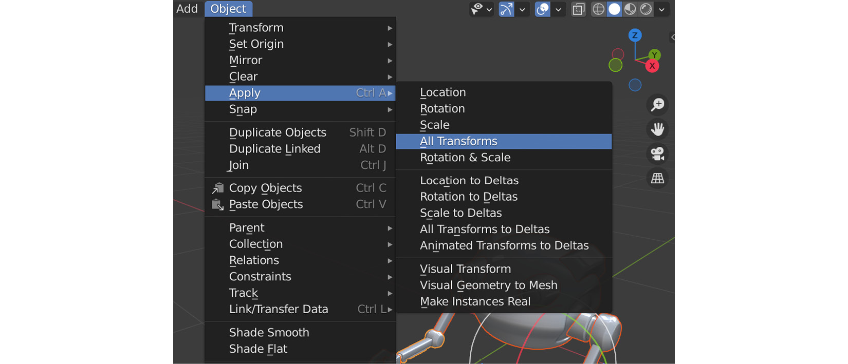
Figure 13.2 – Apply | All Transforms
Everything is now in place for the next step.
Body and left arm bones
Now, let's create the skeleton for our robot:
- In the Perspective view, go to Add | Armature, as shown in the following screenshot:
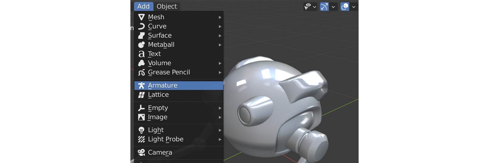
Figure 13.3 – Armature
- With the armature still selected (the Add Armature dialogue at the bottom left will disappear if you deselect it), set Radius to 0.2 m and make sure that, under Viewport Display, the In Front and Axes boxes have been checked, as shown in the following screenshot:
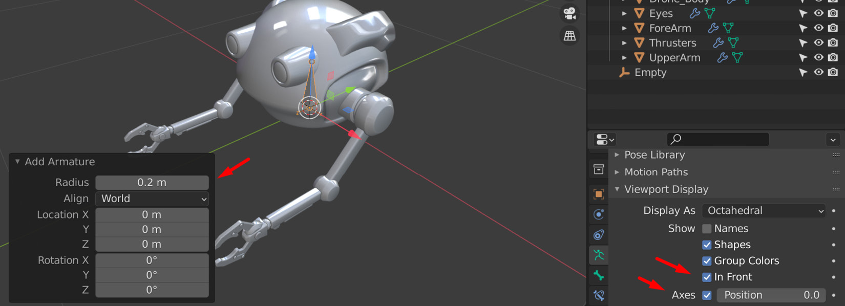
Figure 13.4 – Add Armature
Note
If the armature doesn't appear at the origin of the scene, you probably need to reset the 3D cursor back to the world origin. The armature will be created on the cursor just like other objects. To do this, go to Object | Snap | Cursor To World Origin.
- Switch to the Right Orthographic view and Edit Mode, as shown in the following screenshot.
- Select Bone and then click Armature | Duplicate, as shown in the following screenshot:
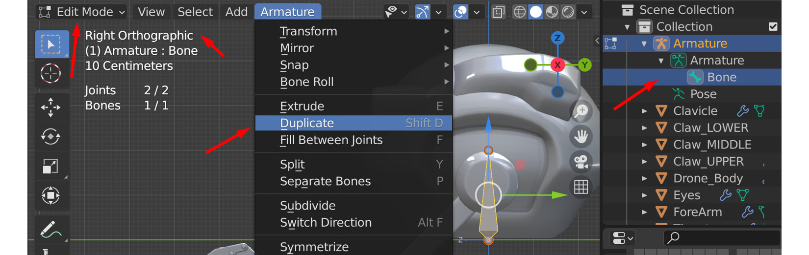
Figure 13.5 – Duplicating the Bone object
- Place the new Bone.001 in the middle of the mass of the body of the robot. Set X and Y in the dialogue to 0 m – you can round off the Z property if you want to get the closest cm, but this isn't essential:
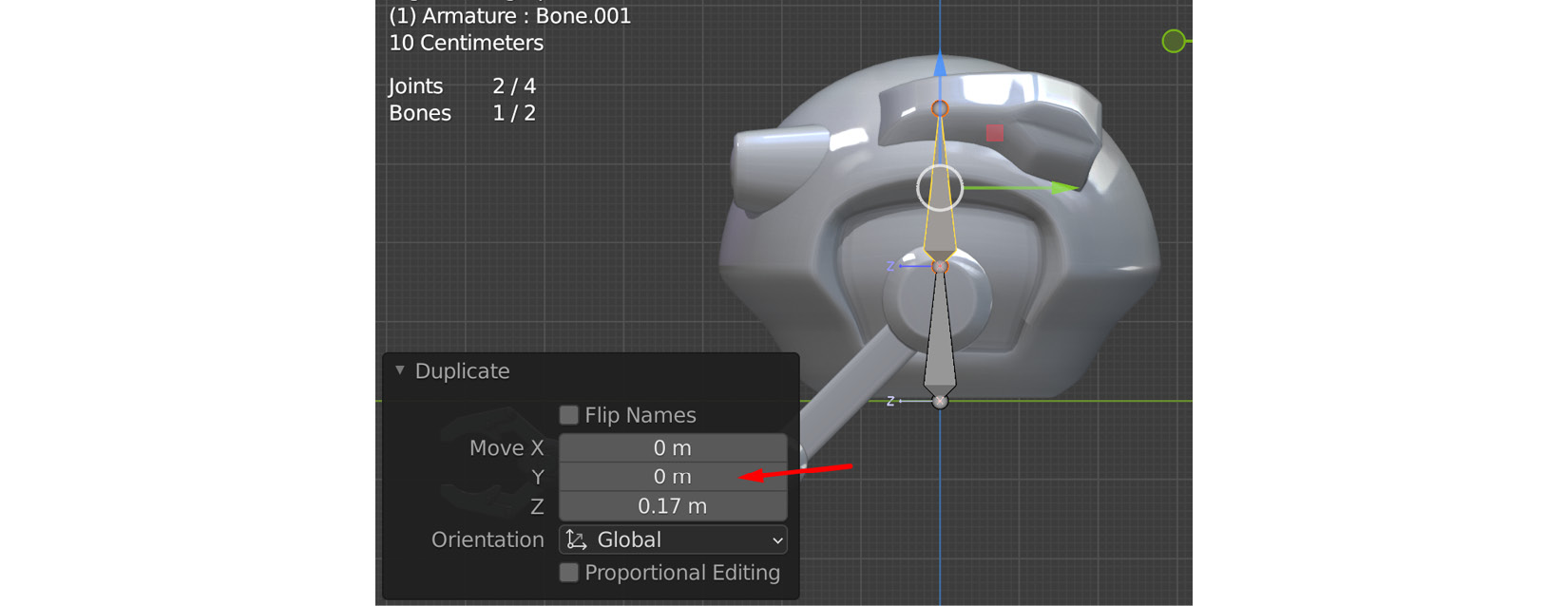
Figure 13.6 – Placing Bone.001
- Switch to the Front Viewport option and while Bone.001 is still selected, select Armature | Duplicate to duplicate it again. This time, position the new Bone.002 where the shoulder joint would be and in the middle of the arm from the front view, as shown in the following screenshot:
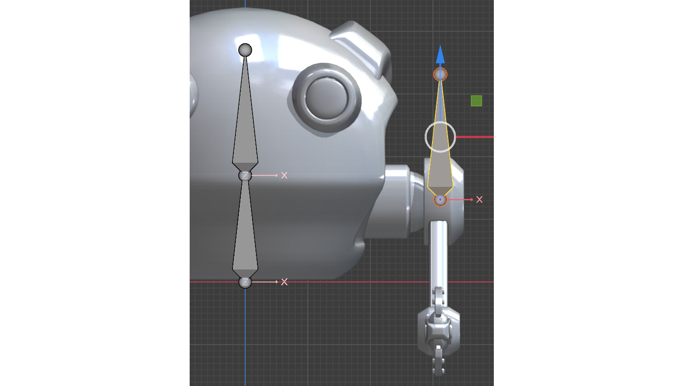
Figure 13.7 – Duplicate bone for the shoulder bone
- Switch to the Right Orthographic view again.
- Switch Viewport Display to Wireframe. Then, set Viewport Display | In Front to off for the bones. After that, zoom into the central point where the robot shoulder cylinder mesh edges converge to find the more accurate middle:

Figure 13.8 – Bone for the shoulder position
- With Bone.002 still selected, move it so that it aligns with the center of the shoulder cylinder where the edges converge:
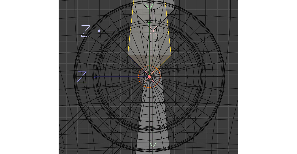
Figure 13.9 – Bone for the shoulder position
- Zoom out while in the Right Orthographic view and select the little sphere at the end of Bone.002. Then, move it to the position of the robot arm's elbow, as shown here:
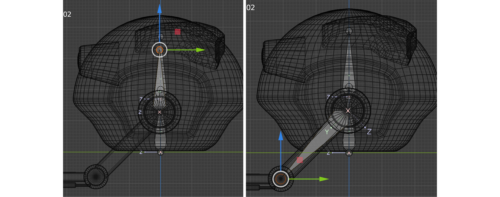
Figure 13.10 – Bone for the elbow position
- Zoom in on the elbow and place it as accurately as visually possible in the center of the elbow cylinder, as shown here:
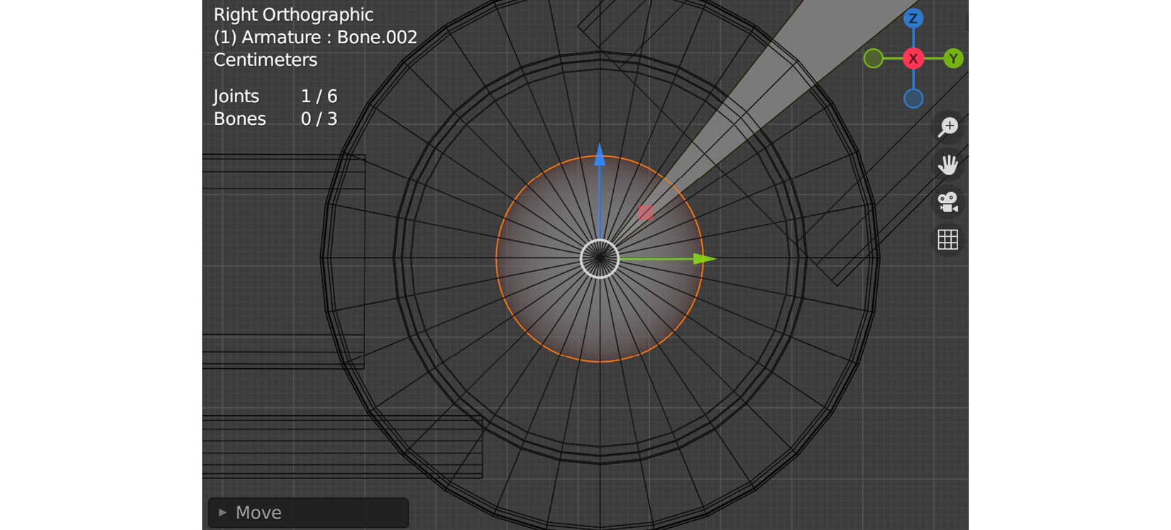
Figure 13.11 – Bone for the elbow position
- Next, with the end of the bone still selected, select Armature | Extrude to create a new elbow bone to span to the wrist. Zoom in and make sure it's positioned in the center of the wrist ball joint after, as shown here:
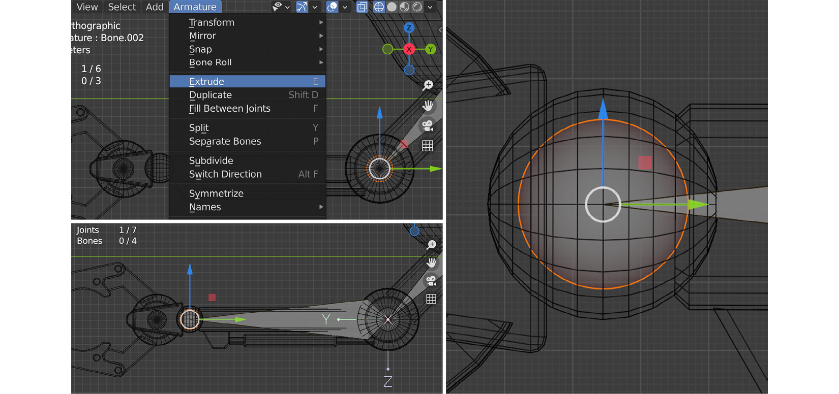
Figure 13.12 – Bone for the wrist position
Everything looks good from the Right Orthographic view, but let's switch to the Top Orthographic view to make sure. In this case, the Wireframe display of the wrist ball is a useful guide to judge if the arm joint chain is in the middle of the arm like when it's viewed from the top. You'll notice that it might be off and not visually exactly in the middle of the elbow joint from the top, as shown here:
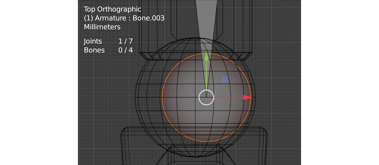
Figure 13.13 – The Top Orthographic view
- This is why it's important to always check from different viewports while you work. To fix this, select both the new shoulder and elbow bones at the same time and move them together until they're in the visual center of the arm as much as possible. In this case, the center can easily be identified by the wrist ball joint in the Wireframe view, as shown here:
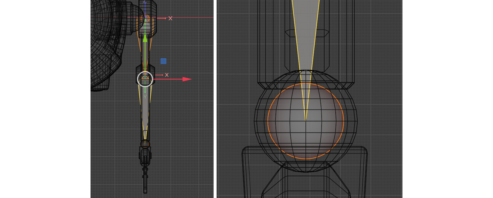
Figure 13.14 – The Top Orthographic view
- Switch back to the Right Orthographic view again and select Armature | Extrude to create the hand bone, as shown in the following screenshot. Zoom in to make sure it's in the center of the hand:
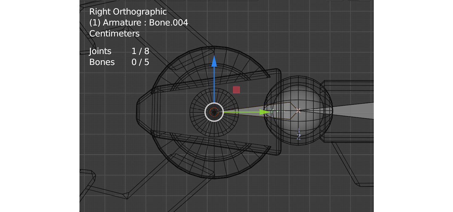
Figure 13.15 – Hand bone
- Now, with the little ball of the hand bone still selected, select Armature | Extrude again to form a lower claw bone, as shown here:
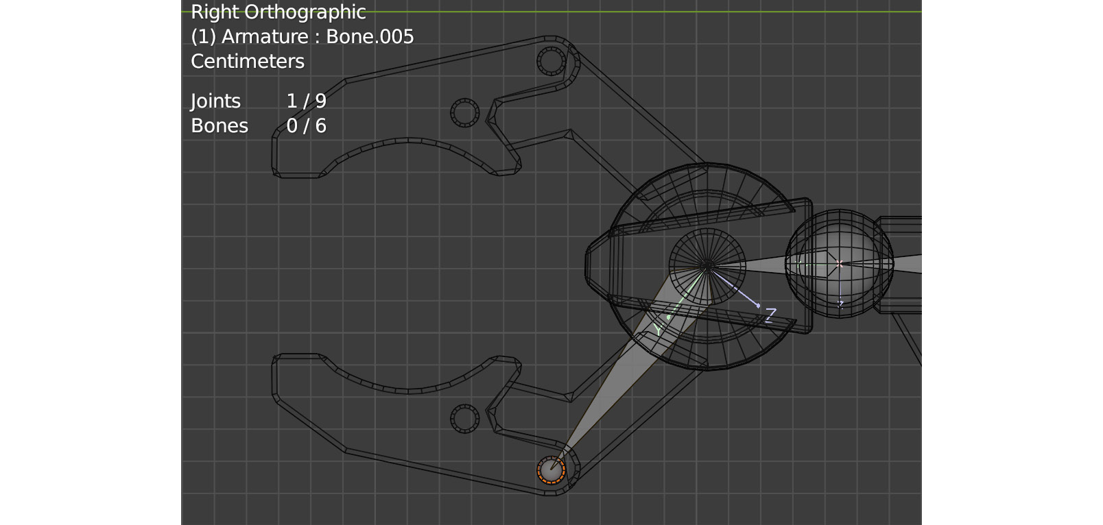
Figure 13.16 – Lower claw bone
- Next, select the end of the hand bone again and, just like you did in Step 15, select Armature | Extrude to form an upper claw bone, as shown here:
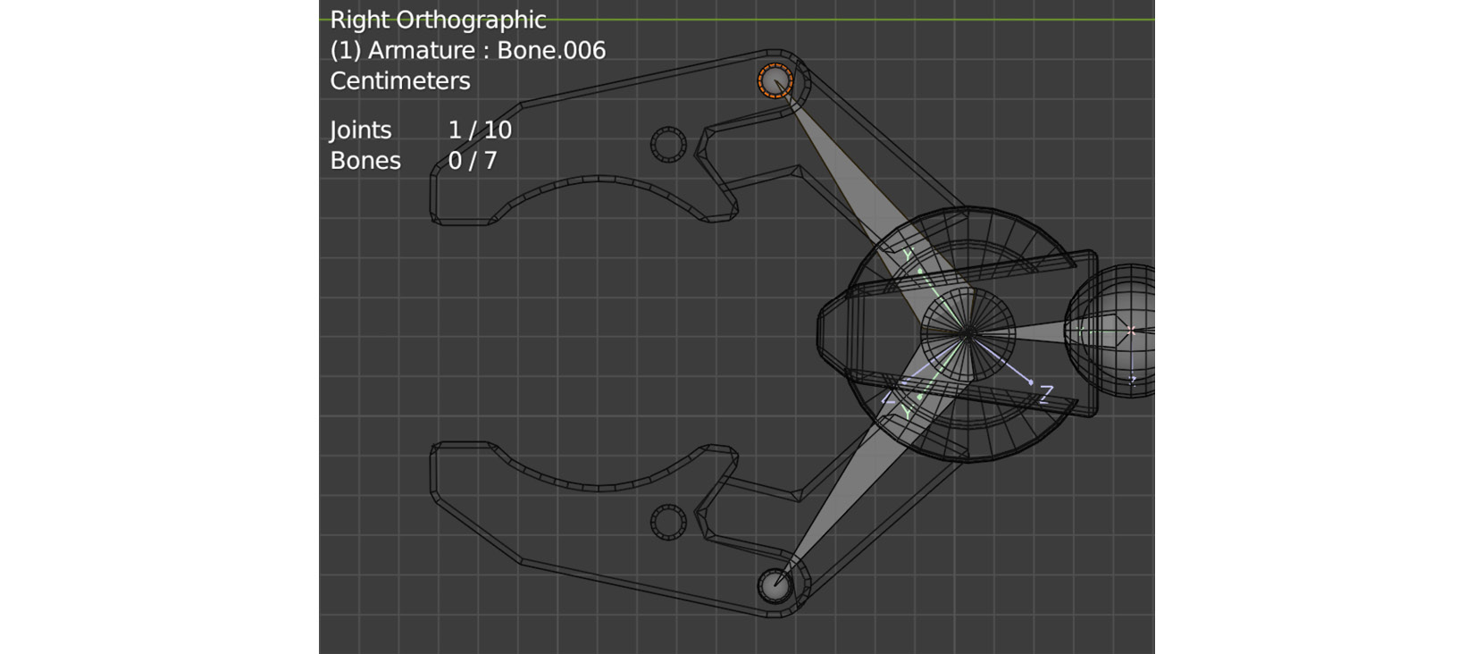
Figure 13.17 – Upper claw bone
With that, we've created our armature with bones for the body and left arm. Instead of following the same process for the right arm, we will take a shortcut by creating symmetrical bones with the Symmetrize tool. However, before we can do that, as always, we need to lay the groundwork. We will do that next.
Renaming and parenting the bones
Before moving on, we need to organize and edit the parenting of our skeleton. Then, we must use a naming convention for the bones so that the Symmetrize tool can use them to create our right arm bones quickly and easily.
If the left- and right-hand sides of our character or 3D model are the same, like most animals and creatures where the right-hand side is a mirror image of the left, we don't need to create bones for both sides. Blender and most other 3D software have something like a Mirror bones tool. In Blender, it is called the Symmetrize tool. The tool recognizes bones that should be mirrored by how they're named.
Blender is good at recognizing the most common industry standard naming formats for bones. A few working examples are as follows:
- Left_Bone
- L_Bone
- Bone.L
- Bone.l
- Bone.right
- Bone_right
I like L_Bone or R_Bone the most. They are short and since the bone name begins with L_ or R_, it doesn't get lost visually when you're organizing hierarchies, skin weight painting, and performing other tasks with the skeleton.
Now, let's rename the bones by following these steps:
- Currently, our bone names would look similar to what's shown in the following screenshot since Blender auto-named them as we created them:
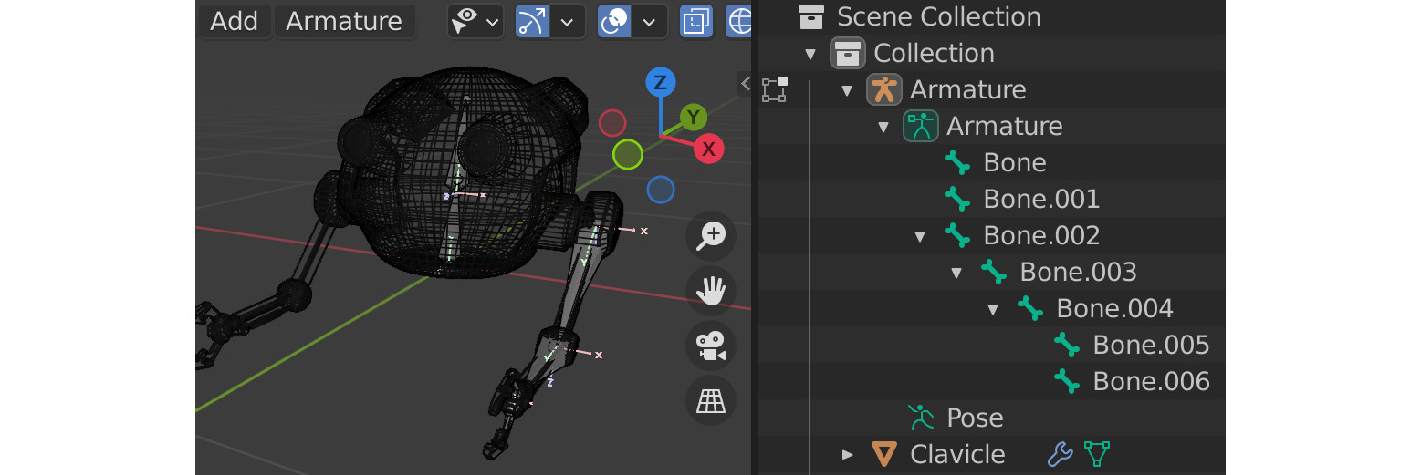
Figure 13.18 – Bone names
- Rename the bones by double-clicking on the bones' names in the Scene Collection area and typing in the new names. Rename them like so:
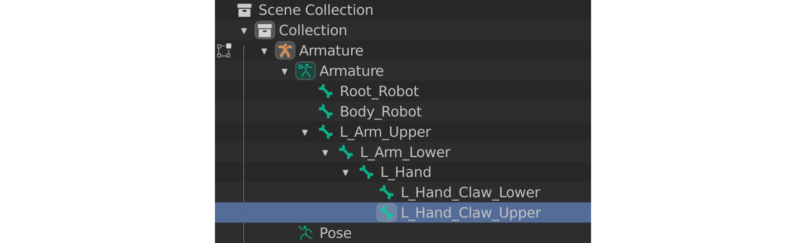
Figure 13.19 – Bone names
- Next, we need to correct and edit the parenting. In Edit Mode, select the Body_Robot and Root_Robot bones by holding Ctrl while you left-click on one and then the other in the Scene Collection area (the order of selection is important since the last to be selected will be the parent).
- Then, click Armature | Parent | Make. Select Keep Offset in the dialogue that appears:
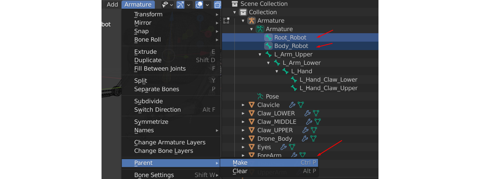
Figure 13.20 – Parent
- Next, select L_Arm_Upper and then Body_Robot. Use Armature | Parent | Make once more, also with Keep Offset selected in the next dialogue.
Our robot armature skeleton hierarchy should now look as follows:

Figure 13.21 – Bones hierarchy
Our Root_Robot bone is the Parent of everything. The Body_Robot bone is the next one in the hierarchy, while the L_Arm_Upper (shoulder) bone is the child of the Body_Robot bone, so it flows right down to the claws on the hand.
With that, our robot skeleton and the left arm bones have been named correctly, and the hierarchy is in the right order. Next, we will create the Right Arm Bones with the Symmetrize tool.
Using the Symmetrize tool
Using the Symmetrize tool on armatures in Blender's Edit Mode could not be simpler. Follow these steps to learn how:
- Select all the left arm bones in Scene Collection by first selecting L_Arm_Upper, holding down Shift on your keyboard, and then left-clicking on the last claw bone in the list – that is, L_Hand_Claw_Upper. This is the same as what you would do when selecting multiple files in Windows 10 Explorer.
- Select Armature | Symmetrize, as shown here:
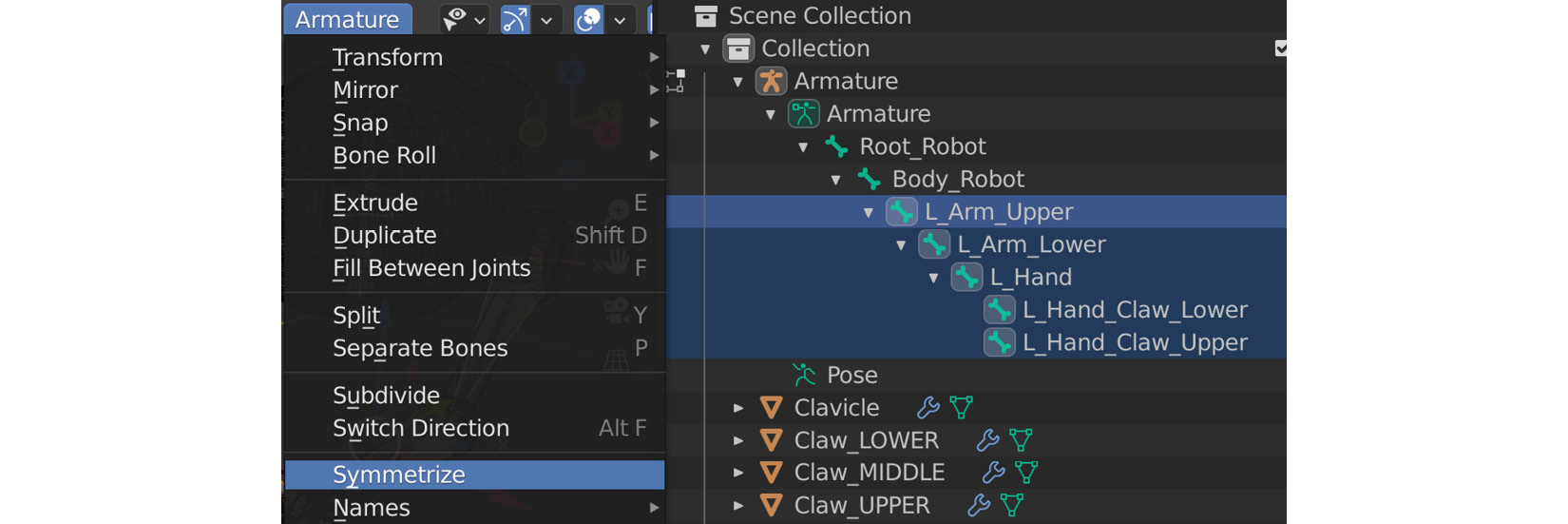
Figure 13.22 – Using the Symmetrize tool to create the right arm
If you look at the result shown in the following screenshot, you will see that Blender created the right arm bones for us. Not only that, but it also renamed the bones in the right arm R_ instead of L_ and did the parenting for us so that the bones are the same as the left arm bones.
At the bottom left in the Symmetrize dialogue, we can change the Symmetrize Direction option to a different axis if needed when our character or 3D model is facing another way. However, in this case, the default direction was correct:

Figure 13.23 – Right arm result
With that, we have successfully created a full skeleton for our robot character. Before we skin our Robot 3D model to our skeleton, we need to check our bone Local axes and Orientations since this will be important later in this book.
Checking and editing the local joint orientations of the joints
We've completed our robot skeleton, just like we did for our Alien Plant in Chapter 11, Alien Plant Joint Setup in Blender. However, there's a difference between our Alien Plant and our robot. Later in this book, we will use an inverse kinematics (IK) animation controller on our robot arms. Don't worry about what exactly an IK controller is at this point. We will get to that later, in Chapter 15, Creating a Control Rig with Basic IK Controls for the Robot in UE5. All you need to know for now is that our Bone Orientations and Local axes need to be set in a certain way for our robot arm to animate correctly with an IK controller.
In general, it's good to have clean and sensible bone orientations, so this is very important to be aware of and understand. Next, we will find out what they are.
What is the local orientation of a bone?
To see the local orientation of a bone visually, we do not have to go far. We already switched them on in the Viewport earlier in this chapter, as shown in Figure 13.4.
As you may have noticed by now, 3D software uses X, Y, and Z axes to define the position of a 3D object in the software's 3D world or space. In the same way, the rotation of a 3D object or bone is divided up into X, Y, and Z axes. This makes it easier for us and the computer to know exactly how we want to rotate our 3D object by inputting its X, Y, and Z values or a combination of them, as shown here:
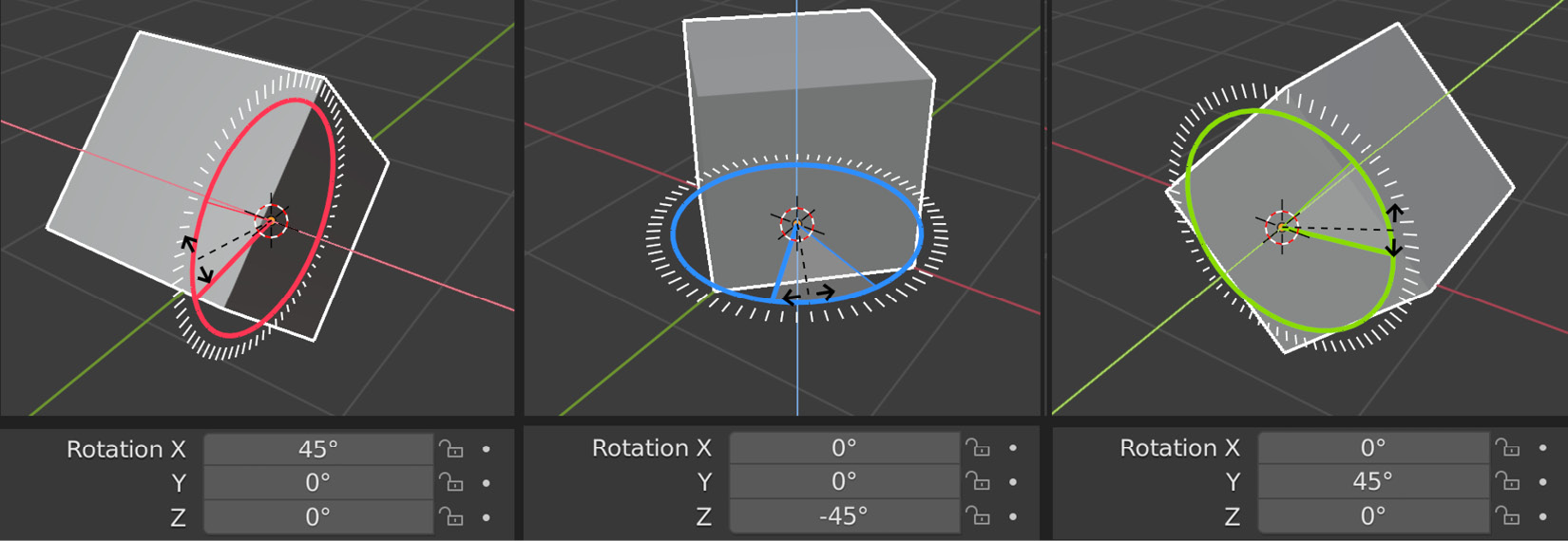
Figure 13.24 – Local rotate combination
To see the Local Rotation Orientation value of any 3D object or bone, select Local from the Transforms Orientations drop-down menu while the Rotate Transform tool is enabled, as shown in the following screenshot:
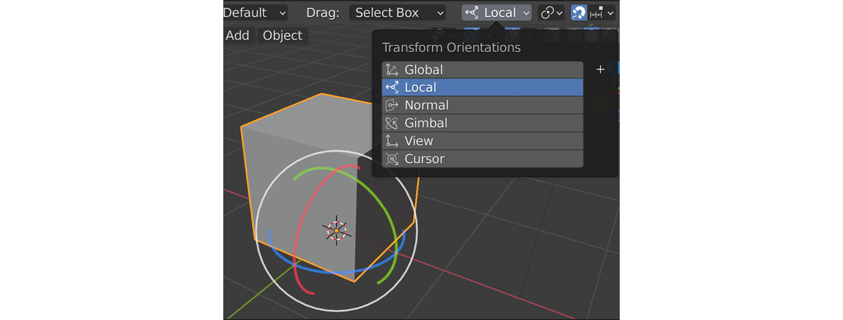
Figure 13.25 – Local rotate
This Local Rotation Orientation value becomes very important for things such as knees and elbows, which can and should only rotate in one direction along one axis. For example, our robot arm's elbow bone should only rotate along the X-axis, as shown here:
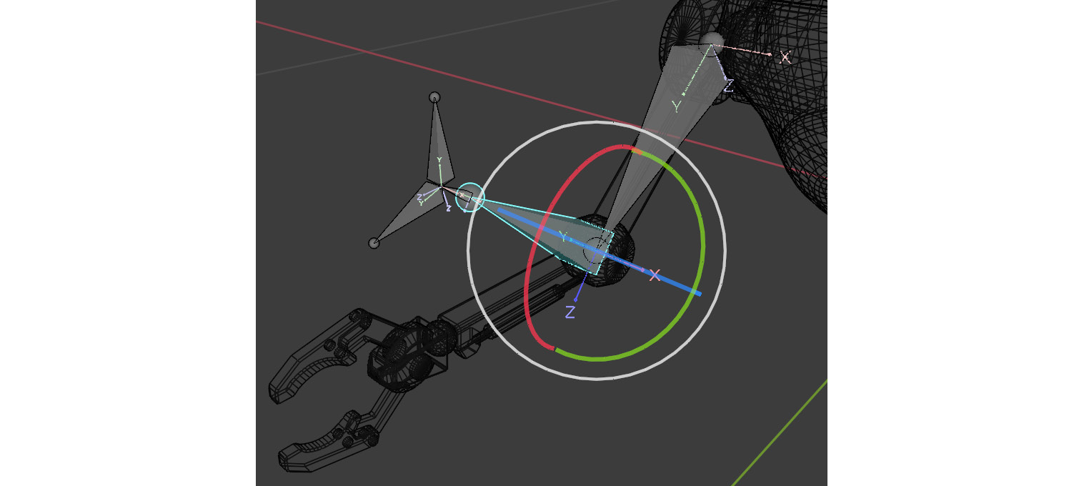
Figure 13.26 – Local robot elbow being rotated
In Pose Mode, if you select the R_Arm_Lower bone, you'll see that our Local Bone Rotate Orientation with the Rotate tool is in very good shape and that it rotates correctly directly along the X-axis if we were to rotate it. With the display axes already on, it's also easy to see visually that they're correct:
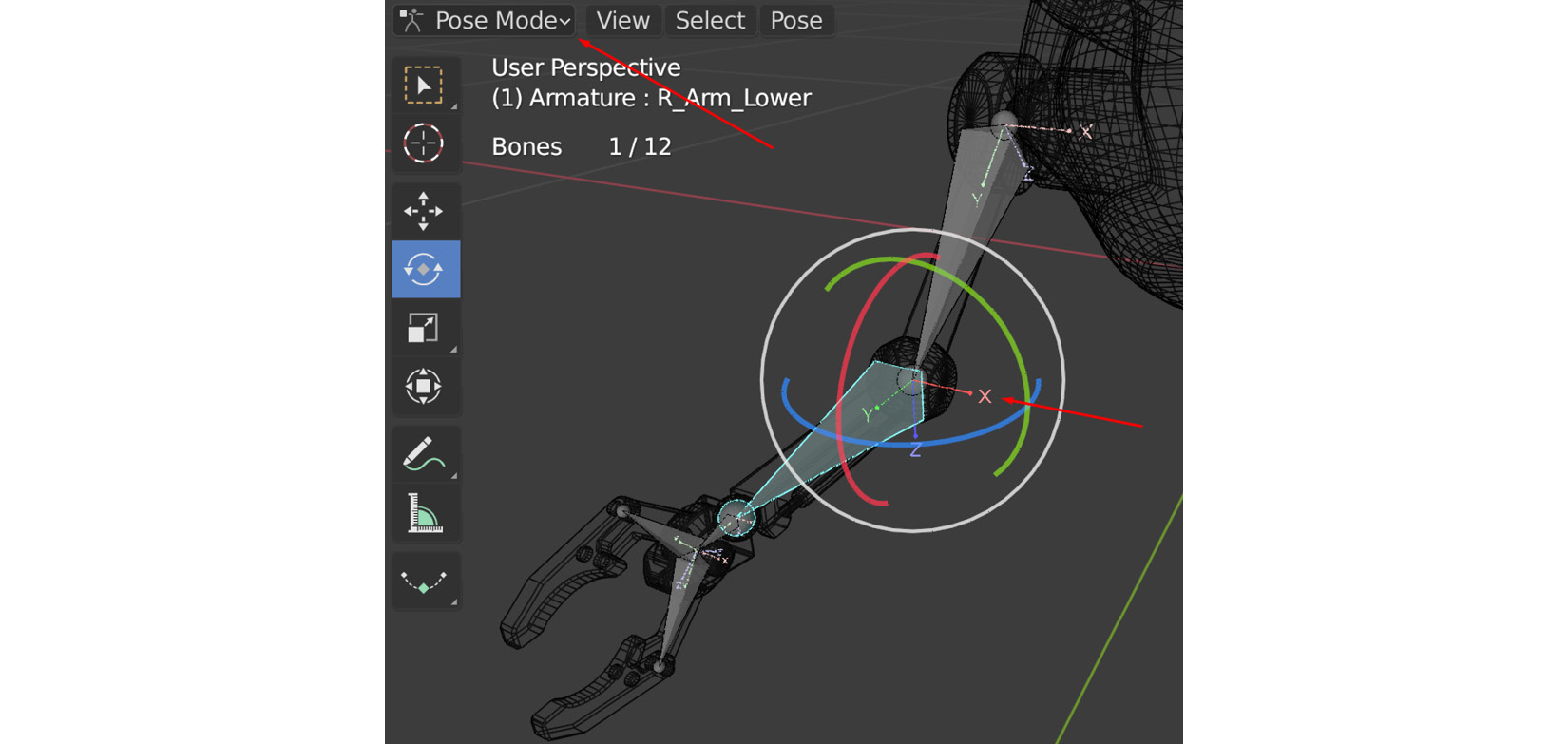
Figure 13.27 – Elbow local axis
Partly because we created and extruded these arm bones earlier in the Right Orthographic view, it was easy for Blender to work out how we want the local axis to be. In this case, we have good local axes in our entire skeleton if we were to check them all. However, very often in the skeleton creation process, we end up in a situation where these joints may have an undesirable Local Orientation. Luckily, Blender (and other 3D software) gives us a way to fix them.
Editing local bone orientations
To learn how to edit the Local Bone Orientation value, let's imagine we want the elbow joint on our robot to deform weirdly. Follow these steps to edit the Local Rotation Axes value without influencing the child bones further down the hierarchy:
- Save the current Blender file for later use since we are about to make a correct skeleton incorrect in the process of learning how to edit bone orientations.
- Switch back to Edit Mode.
- With the R_Arm_Lower bone selected, left-click on the Bone Roll tool, as shown in Figure 13.28.
- Left-click inside the yellow circle and drag your mouse to roll the bone. You can see the Roll value in degrees in the top-left corner.
- Release your mouse button at the desired angle.
- For exact values, you can type them in the Bone Properties tab, under Roll. For example, type in -45, as shown here:
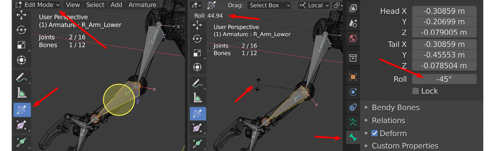
Figure 13.28 – Roll value
- Return to Pose Mode and Rotate the bone on the X-axis. You will see that it behaves very differently when rotating on the new -45 degree angle that's been set:
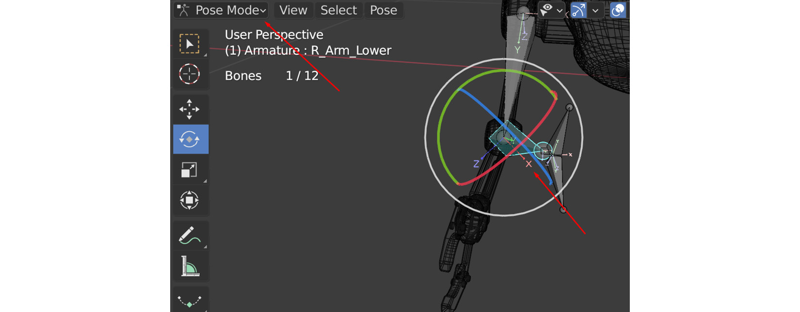
Figure 13.29 – Edited Roll value
- Reload the file you saved in Step 1 before we made these changes. Don't save these changes when opening the file. We want the correctly orientated skeleton back for the last part of this chapter.
With that, we have learned how to edit our local bone orientations if needed. This will come in very helpful at some point if you continue to build character rigs in the future. Next, we'll move on to the last part of this chapter and skin our robot in a rigid way.
Skinning the robot to the skeleton in a rigid way
In the previous chapter, we learned how to paint the skin weights with the Skin Weight Painting tool. However, there's also another more direct and exact way to assign specific skin weights to specific vertices on our 3D model. In the case of our robot, this is the perfect situation to try this method.
Our robot has rigid, solid, and unbendable separate moving parts. In this case, we know that every moving part will have to follow their bones 100%. Rather than weight painting each part at 100% after assigning Automatic Skin Weights, we will do so in a different way to speed up the process.
As always, let's make sure our model is ready before we skin.
Preparing the model and collapsing modifiers
If parts of the robot model have modifiers applied to them, such as Mirror, it may complicate how we select the vertices for our skinning process, we need to remove them. To find out if you have modifiers on any of the robot parts, in Scene Collection, expand the hierarchy of the object. To get rid of (or collapse) the modifiers, in Object Mode, select Object | Apply | Visual Geometry to Mesh, as shown in Figure 13.30.
Go through all your robot parts until there are no modifiers left, as shown in the following screenshot:
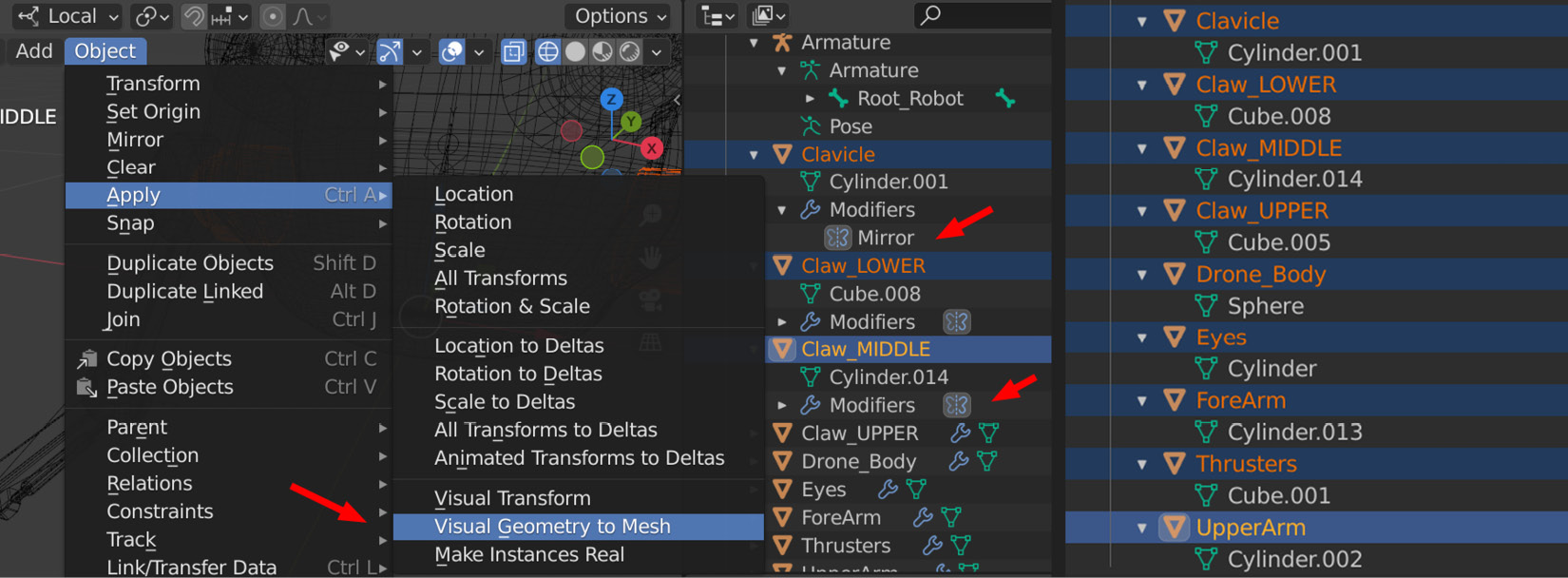
Figure 13.30 – Collapsing modifiers
Now that the parts of the robot are ready, let's skin them.
Skinning the robot body parts
The first part of this process is almost the same as what we laid out in the preceding chapter but with a slightly different skin parenting. Instead of using Parenting | With Automatic Weights, we'll use Empty Weights so that you can start with empty vertex groups. Because we will assign vertex weights manually, it is better to start from a clean slate instead of battling automatic skin weights that have been assigned by Blender. Follow these steps:
- In Object Mode, select one of the robot body parts, such as Drone_Body. Then, select an armature. As we mentioned previously, selection order is important.
- Parent Drone_Body to the armature by applying Object | Parent | With Empty Groups, as shown in the following screenshot:
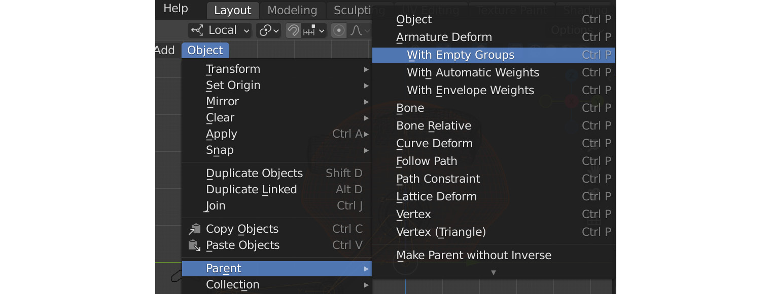
Figure 13.31 – Selecting vertices
- Repeat this process one by one for every robot body part until they're all skinned to the armature individually.
We now have all the parts of the robot skinned to the skeleton. It will function, but if you go to Pose Mode and move the bones, you'll notice that it doesn't deform correctly since the vertex groups are still empty. Next, let's do the rigid skin weights.
Assigning exact skin weights to vertices
In this section, we'll learn how to assign the exact values of an individual or whole group of vertices to a specific bone. We know that we want the robot body parts to follow specific bones 100% so that the parts can stay rigid and not bend between bones like an organic or soft and bendy model would. Follow these steps:
- Select one of the robot body part models. In my case, it will be Drone_Body.
- Go to Edit Mode in Blender. Select Vertex select, as shown in Figure 13.32.
- Select all the vertices in the robot body part model.
Note
This can be done easily by selecting one vertex from each group of linked polygons. For example, if your arm is made of a simple cylinder and a long box, select one vertex from the cylinder and one vertex from the box. Once selected, go to Select | Select Linked | Linked or use Ctrl + L (the default Blender shortcut).
Also, putting Blender in X-ray mode using the top-right display options means that you'll be able to select front and back vertices by just Select Box dragging over the entire mesh for quick selection. By far the quickest way to select all the vertices of an active object in Edit Mode is using the default Blender shortcut key – that is, A.
- Click on and open the Object Data tab and expand Vertex Groups, as shown in the following screenshot:

Figure 13.32 – Vertex Groups
We know we want all the Drone_Body vertices to follow the Body_Robot bone 100%.
- In Vertex Groups, select the Body_Robot bone's Vertex Group, as shown in Figure 13.33.
- Make sure that Weight is set to 1.000 (100%) and click on Assign:
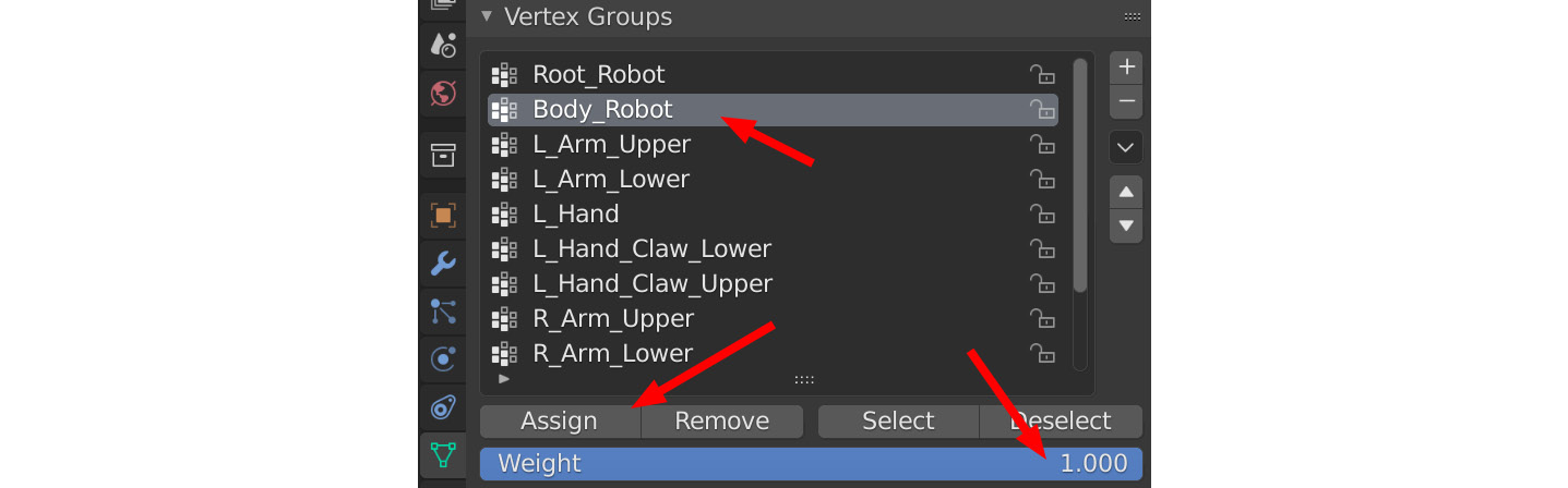
Figure 13.33 – Assigning vertex weights
Because we had all the vertices selected in our robot body and then assigned them to the Body_Robot bone at a value of 1.000, these vertices will now follow the Body_Robot bone 100%. You can test this now in Pose Mode. Always test in-between the steps to make sure what you've done works.
Important Note
Depending on how your robot model is split up and constructed, you need to think through what part should follow what bone vertex group. Note that the main body of the robot is skinned to the Body_Robot bone, NOT the Root_Robot bone, and so should all the static attachments to the Robot body be,such as the Thrusters, Clavicle, and Eyes meshes.
On my Robot model, the left upper arm and right upper arm are parts of the same 3D model. In this case, I must first select the vertices on the left upper arm, assign them to the L_Arm_Upper bone vertex group, and then select the vertices on the right upper arm and assign them to the R_Arm_Upper bone vertex group. This logic applies to the rest of the skinning. This is also why naming bones properly is important – it makes assigning them easier.
- Repeat this process for all the other robot body part models. Match the model vertices selection with the correct bones and assign a weight. Make sure to exit Edit Mode and use Object Mode after each weight assignment to select the next robot body part object; then, enter Edit Mode again to do the assignment.
- Test what you've got in Pose Mode by rotating each bone to see if it all works the way it is supposed to, and that the right part of the robot follows the right bone. Undo after each rotation to return to the original pose. Alternatively, with all the bones selected in Pose Mode, right-click in the Viewport and select Clear User Transforms to return the bones to their original skinned pose. This is not essential, but it keeps the scene clean when you exit Pose Mode, as shown in the following screenshot:

Figure 13.34 – Testing in Pose Mode
- Save the Blender file once you've done all the skinning on the robot body parts.
Advanced Skinning Tip
This method can also be useful for assigning not only rigid weights but also blends when you get more advanced with skinning. If the value is set to 0.5, for example, you can assign a blend between two or more bones, such as an elbow.
If you want to set a 50%/50% blend on a ring of vertices in the middle, between a parent and child bone (such as an elbow), select the ring of vertices and assign it at a Weight value of 1.000 to the parent bone. This will ensure you start with a clean full weight value on the selected vertices.
Then, while the ring of vertices is still selected, change the weight value to 0.5 and assign it to the child bone. Now, your ring of vertices should be a perfect blend between the two bones. This can be any blend value, be it 30%/70% or 10%/90%, depending on what you're trying to do and what looks good.
With that, you've learned how to assign specific and exact vertex weights to bone vertex groups. This will be a very helpful tool in the future.
Summary
In this chapter, you learned how to create a more advanced skeleton and check its joint orientations. You learned how to edit those orientations in case you need to in the future. Finally, you learned a more exact and direct way to assign skin weights that is particularly useful for rigid skinning.
This is the last chapter of this book that we'll do in Blender. From now until the end, we will do almost everything in Unreal Engine 5 (UE5). In the next chapter, we will learn how to rig our models in UE5 to make them easy to animate.