


Advanced solution topics
Although solutions can be built completely within IBM Case Manager Builder application, more advanced customization is often required. For example, a loan application might require a web services call to a loan rating application or when a document is added to a case, the case owner must be notified via email. Such activities require capabilities of the underlying system that are beyond the skill set of the Case Manager Builder business user target audience. This chapter describes some of the advanced capabilities that are available within the system and the tools available for using those capabilities.
This chapter includes the following sections:
12.1 Introduction
Many solution design and editing tasks are accomplished in the IBM Case Manager Builder application. That user interface abstracts the complex underlying configuration of solution design and editing into a simplified case-oriented user environment.
IBM Case Manager provides the Step Designer for creating and managing tasks within the Case Manager Builder. The following task components are provided:
•Activity steps
•Attachments
•Properties
•Routes
•Rule steps
•Stub steps
•Workflow groups
There are many configuration options for each of these components that allow the Step Designer user to create and manage complex workflow operations within a case.
This chapter is intended for the user who works with the solution in ways that are not available in the Step Designer application. Others that are involved in solution design should review these topics to better understand the capabilities that are not accessible from the Case Manager Builder application.
The person who performs the activities that are described in this chapter might have one of many titles in an organization, such as business analyst, IT administrator, developer, systems engineer, and architect. This chapter describes activities that are not traditional developer activities because actual programming is not required.
Configuration activities in this chapter are similar to advanced macro programming because the user drags configurable operations into a workflow map instead of writing code in a programming language. Although understanding programming principles is helpful, knowledge of a programming language is not required. For the purposes of this chapter, we call this person the solution designer.
The solution designer is expected to have advanced training in workflow design and in the underlying content and workflow environments. IBM provides several training courses to prepare the solution designer to do this type of workflow design and editing.
We also recommend that you review the following IBM Redbooks publications:
•IBM FileNet Content Manager Best Practices and Recommendations, SG24-5447, which is available at this website:
•Introducing FileNet Business Process Manager, SG24-7509, which is available at this website:
|
Note: IBM FileNet Business Process Manager was renamed as IBM Case Foundation.
|
12.2 Process Designer integration
A solution designer can use a combination of the Case Manager Builder Step Designer and the Process Designer application for advanced solution editing. Process Designer allows the advanced user to edit complex workflows and it provides for advanced manipulation of the target execution environment.
For more information about enhancing solution designs by using Process Designer, see the IBM Case Manager Information Center at this website:
12.2.1 Accessing Process Designer
You can access Process Designer from IBM Case Manager Builder and from the Process Designer that is hosted by Workplace FileNet Workplace XT.
Accessing from IBM Case Manager Builder
The Process Designer is integrated with Case Manager Builder. In distributed environments, make sure that the proper library JAR files are installed for Process Designer to function property with the Case Manager application.
For more information, see IBM Case Manager Information Center at this website:
Process Designer is accessible within Case Manager Builder at the Solution and Task levels. Figure 12-1 shows the option of using Process Designer within Case Manager Builder at the Solution level.

Figure 12-1 Accessing Process Designer from Case Manager Builder’s Solution level
When a solution or task is opened by using the Process Designer in this manner, the multiuser editing mechanism protects the solution artifacts from editing conflicts. Workflows and workflow configuration functionality (including roles and in-basket definitions) are editable only if a lock is granted for the items.
For more information about multi-user editing, see 5.4.1, “Multiple user solution development in Case Manager Builder” on page 167.
Figure 12-2 on page 457 shows the option of opening Process Designer within Case Manager Builder at the Task level.

Figure 12-2 Edit Task in Process Designer
Table 12-1 lists the differences between solution-level integration and task-level integration.
Table 12-1 Differences between Solution level and Task level integration
|
Solution-level integration
|
Task-level integration
|
|
Process Designer selectively locks portions of the solution as they are accessed.
|
Process Designer locks the selected task.
|
|
The user can edit all of the unlocked task workflows and the solution workflow configuration1 that are associated with the case type.
|
The user can edit unlocked task workflows only.
|
|
The user can edit the solution configuration objects such as Views → Configuration, Views → Roles, and Views → In-baskets are enabled
|
Advanced solution configuration is disabled.
|
1 Queue, roster, and in-basket configurations.
Accessing from Workplace FileNet Workplace XT
When Process Designer is started as an applet in Workplace FileNet Workplace XT, it accesses solutions through direct access to the object store where the solution elements are stored.
For Process Designer to work properly with case elements, the proper libraries must be installed. In distributed environments, it is possible they were not installed properly. For more information about the proper configuration for WorkplaceXT, see this website:
http://pic.dhe.ibm.com/infocenter/casemgmt/v5r2m0/topic/com.ibm.casemgmt.installing.doc/acmin141.htm
12.2.2 Solution editing
You can edit a solution by using the Process Designer. This is equivalent to editing the solution from the Case Manager Builder, except that the solution designer retains the ability to modify other solution elements in Case Manager Builder.
Complete the following steps to edit the solution from the Process Designer:

Figure 12-3 Edit solution through Process Design
2. Select the solution to edit by browsing to the object store and selecting the solution definition.
Case Manager solution documents are stored in a design object store. Solution documents are stored in <Object Store> → IBM Case Manager → <Solution Name>.
Figure 12-4 shows the Customer Complaints solution that is stored in CMDOS → IBM Case Manager → Customer Complaints.
Figure 12-4 Solution document hierarchy
As with solution editing that is listed in Table 12-1 on page 457, you have control over most aspects of the solution. The solution or task is opened by using the multiuser editing mechanism that protects the solution artifacts from editing conflicts. That mechanism ensures that workflows and workflow configuration are editable only if a lock is granted for the items.
12.2.3 Process editing
You can edit a workflow process by using Process Designer. This editing method is used to correct problems with the workflow that prevent it from being opened as part of a solution.
|
Warning: This method should be used only when a solution workflow cannot be opened through other methods. Otherwise, avoid accessing workflows in this manner because it bypasses the built-in Case Manager multiuser locking mechanism. When a workflow is opened this way, it is opened as a stand-alone workflow that is independent of the Case Manager environment.
|
Complete the following steps to open the workflow in the Process Designer:
1. Start the Process Designer and select File → FileNet → FileNet Open/Checkout.
2. Select the process to edit by browsing to the design object store and selecting the workflow object.
Because this way of opening a workflow process is outside the scope of a solution workflow, validation is run against the running workflow system. Solution properties, queues, and so forth, that are not deployed to the running workflow system can result in false failures. Further, inserting operations can cause a workflow to not be opened in Case Manager Builder.
As of Case Manager version 5.2, multiuser editing of a solution creates locking that is circumvented when this method is used. Again, you should refrain from the use of this editing method to situations where directed to do so by IBM support.
For more information about multi-user editing, see 5.4.1, “Multiple user solution development in Case Manager Builder” on page 167.
12.2.4 Activity parameters in Process Designer
Because they are so flexible, activity steps often require special configuration. Understanding how to access the parameter configuration options helps you better implement them.
Figure 12-5 shows the most common method for adding workflow data fields to an activity step. The user selects the data field under the Available Parameters or the Selected Parameters columns and moves them by using the arrows that are between the columns.
Figure 12-5 Step parameters
When the Business Objects icon is selected on the step, the window that is shown in Figure 12-6 opens. The user selects the case or the task property by using the drop-down menu. The selected parameters appear without their F_CaseFolder and F_CaseTask prefixes in the selected properties column.
Figure 12-6 Business Object parameter selection
Figure 12-7 on page 462 shows the step details of the use of the advanced editing option. All of the shown step parameters are case properties. Workflow data fields appear without the function icon and the expression column matches the Name column. The expression column shows the value that is passed to the step parameter that is shown in the Name column.

Figure 12-7 Step parameter details
12.3 Shadow fields and queue updates
As of Case Manager 5.2, enhancements in handling case properties within the workflow system removed the need for shadow fields (for more information about shadow fields definition, see 12.3.1, “Shadow field defined” on page 463). These enhancements have implications for new tasks and older tasks in solutions that were upgraded from previous versions of Case Manager. We recommend that you refrain from the use of shadow fields in any solutions because their use can lead to confusion and unexpected behavior.
We include the description of shadow fields in this section only for older tasks that still have and must use shadow fields.
When a Case Manager solution is upgraded to 5.2, shadow fields are not removed. You can and should remove these shadow fields unless you used them for a specific purpose. Upgraded solutions can include operations that use shadow fields as workflow data fields. Therefore, before shadow properties are removed, the workflow must be examined to ensure that removing the shadow fields does not cause unexpected results.
12.3.1 Shadow field defined
A shadow field is a workflow data field that is named the same as a case property. They were instituted to provide a mechanism for displaying case properties values on in-baskets. Both case properties and workflow data fields are used as variables in the workflow. Table 12-2 lists the types of workflow variables.
Table 12-2 Comparison of workflow variables
|
|
Naming
|
Scope
|
Example
|
|
Case Property
|
F_CaseFolder.<solution prefix>_<name>
|
Global to case
|
F_CaseFolder.TEST_TaskTrigger
|
|
Shadow Field
|
<solution prefix>_name
|
Local to workflow
|
TEST_TaskTrigger
|
|
Example
|
data_field_name
|
Local to workflow
|
TaskTrigger
|
The example that is listed in Table 12-2 shows how three different variables for TaskTrigger are available to a task workflow. When a case property and its shadow field are present in a workflow, the case property or the shadow field value displays in a queue. Further, when a task workflow starts with a shadow field, the value of the shadow field is set to the Case Property value by the Launch Event processor.
The case property and its shadow field continue to exist as two independent variables that are available to the workflow designer. We recommend against the use of shadow fields for new task workflow steps to reduce confusion. The use of a like-named Data Field for a case property, such as TaskTrigger alongside F_CaseFolder.TEST_TaskTrigger, remains an acceptable practice. Further, solutions that are upgraded from older versions should be evaluated regarding how existing shadow fields are used.
12.3.2 Case properties, queues, and work items
Case properties are stored on the case folder object. Queue information is a snapshot of a subset of the work object that is stored in easily accessible database tables for performance reasons. The remainder of the information for a step is stored in the workflow work object.
In Case Manager, work items are assigned to three types of queues: individual user, group, and system queues. Work items that are assigned are retrieved from the queues for processing. Each queue entry presents a snapshot of the available workflow variables at the time when the entry was created or modified. The Case Manager Builder application handles configuring queues when roles and in-baskets are created and modified. Advanced configuration is available to the solution designer through direct configuration of the queue settings by using Process Designer when in solution edit mode.
Queue updates
When case properties are made available on a queue for use in an in-basket, those properties are automatically tagged for Event Update and the Value Provider is set to F_CaseFolder. These related settings are visible when the solution is edited in the Process Designer but not visible in the Case Manager Builder.
The following statements are true in relation to queue updates:
•Event Update and Value Providers are automatically configured on each queue when the role is created in the Case Manager Builder. It is possible to have Queue A set up differently from Queue B. Therefore, two queues might display different information.
•When the Value Provider is set to F_CaseFolder, the workflow system uses the named case folder property as the source for the queue entry. Otherwise, the queue entry uses the named workflow data field value.
•Event Update controls how often the queue entry is updated. If selected, it triggers an update to the queue entries for that property name whenever the Case Folder that is specified by the F_CaseFolder Value Provider is updated. Changes to the value on the case folder (regardless of the source) results in an update to all queue entries for that named variable. Because the case property is not stored on the work object, the work object is not modified.
•When a shadow field exists in the workflow, Case Manager Builder configures the step to display the case property value on activity steps. Further, the solution designer can inadvertently attach the wrong parameter to a step depending on how they add the parameter to the step in process designer.
•Because a shadow field is stored on the work object, its value is accessible when the work object it queried. Incorrectly expecting the two independent values to be the synchronized is one of the areas where confusion arises.
Depending on the mechanism that is used to view a parameter that is associated with a case or a task, different values are returned. Users confuse the values because of their shared name.
Troubleshooting solutions requires the involved users to carefully communicate what value they are reviewing. When a shadow property exists, the following values with the same name are available for review:
•Case property from the case folder
•Queue value
•Shadow property value from the work object
For example, the search and the case information widgets use the case folder objects while the in-basket widget shows queue entries. The vwtool and Process Administrator applications display granular information about running workflows that require a special understanding of the core workflow system.
Queue configuration details
When you are working on solutions where there are shadow properties, the solution designer must look at several parts of the configuration to understand how the values are displayed on the queue. They must review the queue configuration with the individual activity steps to understand if the entries that are displayed on the queue are as expected.
To access the advanced queue settings (as shown in Figure 12-8), open the solution in Process Designer and click View → Configuration, expand the work queues, right-click a queue, then click Properties → Data Fields.
Figure 12-8 Queue Event Update and Value Provider Settings
12.3.3 Shadow field synchronization
Step Designer no longer creates shadow fields when a case property is assigned to an activity step. But, it does create entries on the activity step to extract the case properties for the step, as shown in Figure 12-9 on page 466.
The advanced menu on the Step Properties tab provides details about what displays in the user interface. In Figure 12-9, the first operation is interpreted as: F_CaseFolder. CC_UpgradeCategory is a case string field with read/write on the step. It is used on the step as CC_UpgradeCategory. When the step completes or a save occurs, the value of CC_UpgradeCategory is written back to the case because write is set.
Figure 12-9 Advanced View of Step Parameters
When the queue is viewed, the values that are displayed on the queue can differ from what is seen on the workflow object when the Process Administrator or vwtool is used. When an administrator views a work item, they might be looking at the work object, the workflow roster, or the queue record. Each returns different information.
For more information about accessing the step parameters display as shown in Figure 12-9, see 12.2.4, “Activity parameters in Process Designer” on page 460.
For information about vwtool, see this website:
12.3.4 Prior version behavior
When a case property was associated with a task activity step, the Case Manager Builder automatically created a shadow data field in the workflow. Because it was named the same as the case property, people sometimes incorrectly assumed that the case property and the shadow field were kept synchronized. This field is displayed in people’s In-baskets.
When the variable is modified in the Case Manager activity step, the case property updates automatically and workflow data fields are updated by a post assignment that is automatically added to the step by Case Manager Builder. Figure 12-10 on page 467 shows how case properties update the local field when an activity step was created in Case Manager Builder. Case Manager Builder version 5.2+ does not create the After Completion assignment operations.

Figure 12-10 Shadow Field After Completion Assignments
Experienced workflow designers are familiar with these shadow fields and the issues that are associated with their use. Solution designers often use the local variables within the workflow as local parameters. They strategically insert assignment steps to update the case property with the shadow field value. They also were aware that activity steps were configured to retrieve the current case property value and assign it to the shadow field.
When modified outside the scope of an activity step, the shadow field value often differs from the case property value. Workflows that are designed in this way pose a special challenge when the solution is upgraded because removing the shadow fields can cause the workflow to fail or behave unexpectedly.
Case properties do not automatically synchronize with workflow fields. To keep them in synchronization on activity steps and make them visible on the queues, the special configuration assignments that are shown in Figure 12-10 were automatically added to the steps. These operations ensured that the shadow field and the case property were synchronized when the step was run.
Implications
As of version 5.2, builders of new solutions and editors of solutions that are migrated from earlier versions must understand that the values that are displayed on a queue depend on the Event Update and Value Provider settings. They also must understand that the post-assignment operations might not be present on an activity step. Assuming that we have a Case Property with a matching shadow field, Table 12-3 on page 468 shows the possible queue configurations.
Table 12-3 Possible queue configurations
|
Event Update setting
|
Value Provider setting
|
The queue displays
|
Queue update
|
|
checked
|
F_CaseFolder
|
The case property value.
|
When a step that changes the case property completes, the value of the case property is updated on the queue.
|
|
checked
|
F_CaseFolder
|
The case property value.
|
Changes to the Case Folder that is associated with the queue value result in the value being updated on the queue.
|
|
unchecked
|
F_CaseFolder
|
The case property value.
|
Changes to the Case Folder that is associated with the queue do not change what is displayed on the queue for the named property.
|
|
checked or unchecked
|
blank
|
The shadow field value.
|
Event Update has no effect. The queue entry updates with the data field value only when the step is active.
|
Solutions that are transferred from older versions of Case Manager retain their configuration and behavior with the caveat that the queue information is updated. When a solution is upgraded to version 5.2, the activity steps retain their old configuration.
New activity steps are added without the post assignment operations, which means that the solution designer must be aware that the local shadow value is not synchronized with the case property value when the activity step completes. Further, a case property that is added to an activity step results in the suppression of the shadow field changes on the activity step.
When updated workflows are modified, the confusion is worse because an older step might have the post-assign operations to update the shadow field where new steps in the task do not update the local shadow field.
In summary, remember the following points:
•Avoid the use of shadow fields.
•Upgraded solutions might contain shadow fields that largely behave the same as in early versions of Case Manager.
•Modifying case properties or shadow fields that are available on queues trigger a queue update so that the in-baskets reflect the changes.
•In new activity steps, post assignments are not automatically created. Therefore, the case property and the local shadow field might not have the same value upon step completion.
•Custom widgets and other applications that make API calls into the system must be properly configured to retrieve the correct information. The retrieved value can be incorrect because the case property, the queue property value, and the data field in the work object can all have different values for the same property name.
12.3.5 Parallel property changes
Consider the question “What happens when my case property changes in two parallel tasks or in two steps running in a parallel workflow branch?” Both Case Manager Builder users and solution designers must design their solutions while taking into account that case properties are global case variables whose values can be changed at any time through several mechanisms. Case properties always reflect the value that they were last assigned.
If two steps modify a case property, the case property has the value set by the last step when they complete. Further, because of real-time system resource and queuing issues, there is no guarantee which step makes the last change. Consider the following assignment steps that are configured to modify the property F_CaseFolder.ClaimAmount:
•F_CaseFolder.ClaimAmount initial value is 0
– Step A runs the setting F_CaseFolder.ClaimAmount=F_CaseFolder.ClaimAmount+1000
– Step B runs the setting F_CaseFolder.ClaimAmount=10
•If the two steps are queued to run simultaneously, the outcomes might be:
– If Step B runs last F_CaseFolder.ClaimAmount is10
– If Step A runs last F_CaseFolder.ClaimAmount is 1010
Case properties are global variables accessible to any running case task. Further, with the proper permissions, they also are modifiable from the Case Information widget.
The solution designer can create local data fields by using the Process Designer. Those data fields exist only for the duration of the workflow and are independent of the case properties. At appropriate times, the data field values can be assigned to case properties by simple assignment steps.
12.4 Case operation components
Case Manager offers the following case operation components:
•ICM_Operations
•ICM_RuleOperations
The ICM_Operations and its operations that are listed in Table 12-4 provide workflow operations for case management.
Table 12-4 ICM_Operations
|
Operation
|
Description
|
|
addCommentTo
CurrentCase |
Add a comment to the current case.
|
|
addCommentTo
CurrentTask |
Add a comment to the current task.
|
|
createCaseUsingSame
CaseType |
Creates an instance of case by using the same case type.
|
|
createCaseUsingSpecified
CaseType |
Creates an instance of a case for the specified case type.
|
|
createDiscretionaryTaskIn
CurrentCase |
Creates a task instance of a discretionary task type.
|
|
createSubfolderUnder
CurrentCase |
Creates a subfolder under the current case folder.
|
|
fileAttachmentsTo
CurrentCase |
Files attachments to a specified subfolder under the current case folder.
|
|
getCasePropertyNames
|
Returns a list of the names of the properties in a case. This operation is a prerequisite for the createCase operations.
|
|
getCasePropertyValues
|
Returns a list of the property values of a specified case. This operation is a prerequisite for the createCase operations.
|
|
getCaseStructure
|
Returns the case structure for a case. The structure is returned as a list of folder names and document series IDs. This operation is a prerequisite to the createCase methods.
|
|
relateCurrentCase
|
Creates a relationship between the current working case and the targeted case.
|
|
terminateTasksIn
CurrentCase |
Terminates all workflows (tasks) in the current case. Tasks are terminated only if they did not complete and did not fail.
|
|
unfileAttachmentFrom
CurrentCase |
Unfiles an attachment from a case folder.
|
|
unrelateCurrent
Case operation |
Unrelate the current working case.
|
The ICM_RulesOperations provides an operation (see Table 12-5) that is related to integrated rules processing.
Table 12-5 ICM_RulesOperations
|
Operation
|
Description
|
|
executeRule
|
Executes a rule
|
As other workflow operations are needed, more operations are added to these components.
For more information about these operations, see the following resources:
•Adding case operations to a task:
•Adding rule operations to a task by using Process Designer:
12.5 Advanced design examples
IBM Case Manager is built on the core IBM FileNet P8 Case Foundation platform. The platform provides world-class enterprise content management and business management services and access to external web services. The examples in this section are intended to show how some of those services are accessed.
12.5.1 Document arrival email notification
Often we must notify internal or external users about aspects of a case. For example, an insurance underwriter must be notified if a document is added to a submission for which they are responsible. Or, a customer service representative sets a flag on the case they are working so that they receive a notification when an email arrives from the customer.
For our example, we notify a user when a document is added to a case. We use this example to show the use of some of the advanced processing capabilities that are available to the solution designer.
For this example, we assume that there are users who should be notified when a document is added to a case. We create a task that runs each time a document of any type is added to the case. That task extracts information from the document and uses it for the subject of the email and for the email body. We use a case property to determine who is to receive the email message.
The component integrator is part of the toolset from the process services in the Content Platform Engine. It extends the capabilities of the workflow system with Java class public methods. When installed, those methods act as components in the workflow process. For our example, we use the CE_Operations component that is included with the IBM Case Foundation product. CE_Operations provides a suite of operations for manipulating and interrogating content that is stored in the Enterprise Content Management system repositories.
This example uses the simple solution that was developed in Chapter 7, “Building a simple solution: Part 1” on page 211 as the basis. This technique is easily implemented and extended in any solution. For this example, the solution designer creates the task and inserts the activity and stub step configuration that is often done by the business analyst.
Creating the task in Case Manager Builder
Creating the task can be completed by a business user or by the solution designer. The user creates a string property for the email recipient (or recipients), then creates a task by inserting steps and attachments as needed.
Complete the following steps:
1. Log in to Case Manager Builder:
http://<host>:<port>/navigator/?desktop=icm
2. Edit the Customer Complaints solution by mousing over the solution and clicking Edit.
3. Click Properties → Add Property → New.
4. Enter the following information and click OK:
– Name: Notification Recipients
– Description: Comma delimited list of email addresses for email notification
– Maximum Length: 1024
The default maximum length of 64 is sufficient for one email address. Setting the value to 1024 allows for several email addresses without the need for an array.
5. Click Case Types and select the Complaint case type.
6. Click Tasks.
7. Create a task by selecting Add Task → New Task.
8. Configure the task as shown in Figure 12-11 on page 474:
– Name: Supporting Document Notification
– This task starts: Automatically
– This task is: Not required
Figure 12-11 Configure Task General Settings
When you set these preconditions, you can choose to have the task start when a document of any type is added to the case. You also can set up the task to start whenever a document of a specific type is added to the case.
For our example, we are going to send an email when a document of the Supporting Document type is added to the case. We also are going to have the email sent when a document is added rather than the first time a document is added, which is why we set the task as repeatable.
When a task starts that is based on adding a document to the case, property preconditions can be used to decide whether the task starts. For example, we can create a case property Notify on Document Arrival as a true or false Boolean. Then, it can be used as a task precondition to determine whether the task runs.
9. Select the Preconditions tab and configure the following preconditions and then click OK, as shown in Figure 12-12:
– When precondition must be met: A document is filed in the case
– Task is repeatable: Select this option.
– Any document type: Clear this option
– Select the Supporting Document for the document type.
Figure 12-12 Applying preconditions to a task
This completes the task creation and from this point, the business user can edit the steps by using the Step Editor and insert stub steps into the task signifying what is needed. For this case, we save and close the solution at this point.
10. Click Validate → Save and close.
11. If the new task is edited by another user, click Commit to commit the changes.
|
Commit consideration: The user should make sure that all related task and solution changes are committed for two conditions: if another user is editing the workflow or the task is ready to run. If the solution is deployed, the new task runs after it is committed even though it might not be fully configured. If steps are inserted into the task, they should not fail should the solution be deployed before it is configured by the solution designer.
|
Configuration in Process Designer
Now that the task is created, the solution designer edits the workflow to insert the following workflow elements by using Process Designer:
•Attachment property that points to the received document marking it as the starting document.
•Workflow data fields for transient information.
•Component operations to read properties from the newly arrived document.
•Assignment operations to set values on the local workflow data fields that are used in sending the email message.
•Component operation to send an email message.
The task can be created by the business user and the solution designer then completes the more advanced configuration. You can start your solution editing in Process Designer in multiple ways. For this example, we edit the solution from the Case Manager Builder by completing the following steps:
1. To start editing the solution from Case Manager Builder, enter the following URL in a web browser:
http://<host>:<port>/CaseBuilder
2. Go to the Customer Complaints solution (as shown in Figure 12-13) and select More Actions → Open Process Designer to start the Process Designer application on the solution.
Figure 12-13 Edit Solution in Process Designer
3. Edit the Send Supporting Document Notification workflow that was created in Case Manager Step Designer, as shown in Figure 12-14.

Figure 12-14 Selecting a Task Workflow
When a user opens a Task Workflow, this workflow is locked to the user ID to prevent editing conflicts.
When a solution is edited in Process Designer, the solution designer can access the process-related aspects (including the queue definitions) of the entire solution. For example, the solution designer can select steps from one task workflow and copy it to another by editing that workflow.
4. Set up the attachment information by clicking Workflow Properties → Attachments and configure it by using the following information (see Figure 12-15 on page 478):
– Name: Document
– Description: Document
– Initiating Attachment icon: selected
– Array box: not selected
The blue arrows that are shown in Figure 12-15 on page 478 point to the icon and the resulting icon on the attachment. The red arrow points to the Array box.
Figure 12-15 Attachment Configuration
5. Set up data fields information by clicking Workflow Properties → Data Fields and configure the following information:
– Name: Document Title
– Type: String
– Description: The title of the document
The workflow extracts information from the new document and uses that information in the email body and email message.
6. To extract the properties from the document that started this task, drag a component step onto the workflow map. Add the required operations as shown by completing the following steps for each table row:

Figure 12-16 Add getStringProperty using the Add icon
b. Select CE_Operations for the component drop-down list and select getStringProperty from the Operation list, as shown in Figure 12-17 on page 479.
Figure 12-17 Select getStringProperty operation from CE_Operations
c. Enter the operation parameters for sourceDocument, symoblicProName, and return_value, as shown in Figure 12-18.

Figure 12-18 Operation parameters configuration
|
Note: The quotation marks for symbolicPropName are required. For return_value, no quotation marks are used because the return_value is assigned to the data field that we created. When values are entered in process designer, it is important to press the Enter key each time to complete the editing operation.
|
|
Tip: The difference between items with quotation marks and no double quotation marks in Process Designer is that quotation marks are treated as a string. Items with no quotation marks are treated as a variable, whether it is a data field, attachment, or other. You can use the expression builder by selecting Build Expression to assist with supplying values for a field.
|
d. Click OK.
e. Repeat these steps for each value that you want to retrieve from the document.
Figure 12-19 shows the added operation, getStringProperty.
Figure 12-19 Added operation, getStringProperty
7. Complete the following steps to insert steps and routes onto the workflow:
a. Drag an Assignment step from the icon bar onto the workflow map. Set its name to Set email Properties by clicking the step and entering the step name.
a. Drag a Component step from the icon bar onto the workflow map. Set its name to Send email by clicking the step and entering the step name.
b. Insert routes to connect the steps, as shown in Figure 12-20.

Figure 12-20 Steps and Routes
8. Complete the following steps to configure the Send email step, as shown in Figure 12-21:
a. Select the Send email step and add the sendMail operation as you did for the getStringProperty operation from CE_Component.
b. For this step, there are several inputs to the sendMail operation. The Process Designer automatically creates data fields for component steps. This shortcut is why we do not create the data fields earlier. Instead, click in the empty expression field.
If the data field does not exist, the first drop-down menu option is <create [Field Name]>. Add the data fields to the workflow by clicking in each of the empty expressions and selecting the <create from>, <create to>, <create subject>, and <create body> for each of the step parameters: from, to, subject, and body. Figure 12-21 shows creating the body data field.
If there is an existing data field of the correct data type that should be used for an operation, it appears as an option in drop-down list. Because each of the inputs is String data types, they appear as options for each of the steps after they are created.
Figure 12-21 Create Data Fields for sendMail
After the Send email step is configured, click Workflow Properties → Data Fields to see the new data fields that were created.
Figure 12-22 shows the fields with their default values. You can choose to define default expressions and descriptions for the fields at this point. Instead, the assign step set the values by using information from the new document.

Figure 12-22 Configured data fields
9. Configure the Set Email Props step. For each of the data fields in Table 12-6, complete the following steps:
a. Click the first empty field in the Name column and select the name from the drop-down menu.
b. Click the Expression column and enter the expression from Table 12-6 exactly as shown, including the quotation marks.
Table 12-6 Set email Props Assignments
|
Name
|
Expression
|
|
from
|
|
|
to
|
F_CaseFolder.CC_NotificationemailAddresses
|
|
subject
|
“New Supporting Document for Case” + F_CaseFolder.CC_CaseNumber
|
|
body
|
“The supporting document” + documentTitle + “ was received on “ + timetostring(systemtime()) + “. “
|
When values are entered in the Expression field, the editor remains active until you press the Enter key on your keyboard. If you did not press the Enter key, the expression shows with a second set of borders.
After the process is completed, the step is configured as shown in Figure 12-23 on page 483.

Figure 12-23 Assignment Parameters for Set email Props step
10. Before you return to Case Manager Builder, validate the workflow collection by clicking File → Validate Workflow Collection and making any required corrections.
|
Important: Always validate your workflow collection before you save and close your solution in Process Designer. Make sure that there are no errors before you return to Case Manager Builder.
|
11. Close, commit, and deploy the solution.
After all of the required changes are made, you must commit the changes before the solution is deployed.
12.5.2 Creating more in-baskets
Case Manager Builder allows the business analyst to specify roles. A single in-basket is defined for each role. An IT administrator can add more in-baskets for extra server-side filtering or organization. This section describes some use cases for adding in-baskets.
There are various reasons to create more in-baskets for a role. Extra in-baskets can help with server-side filtering on geographic regions or customer status, for example. For the Customer Complaints use case scenario, we create an in-basket for complaint categories. Creating a choice list makes it easy to designate in-baskets.
The following choice list is defined for the complaint categories:
•Product
•Service
•Billing
•Other
|
Tip: As you consider names, remember the special characters that are supported in role names and in-basket names: hyphen (-), underscore (_), and period (.).
|
Complete the following steps to create an in-basket for each category. Apply the in-baskets to the Contact Center role:
1. From Case Manager Builder, select Customer Complaints solution, and click More Actions → Open Process Designer.
2. When you are prompt to select a case type, select Complaint, as shown in Figure 12-24. Because we are editing the in-baskets, we can select any of the task workflows. Click OK when you are done.
Figure 12-24 Selecting Complaint Case Type
Figure 12-25 Selecting In-baskets for a solution
4. Check that we are modifying the CC_ContactCenter queue under Queue for in-baskets.

Figure 12-26 Adding four new in-baskets to the Contact Center queue
6. Double-click each in-basket and rename them to Product, Service, Billing, and Other.
7. Select the first custom in-basket, Product.
8. On the Create Columns and Labels tab, click the Add icon.
Show all fields on the initial role in-basket. Repeat this step for each in-basket. Select all of the boxes and click OK, as shown in Figure 12-27.

Figure 12-27 Adding fields to an in-basket
9. The column labels for each field are not clear to a user. Double-click each column label and rename them to something clearer. Rename the labels to remove the CC_ prefix and add spaces, as shown in Figure 12-28.

Figure 12-28 Renaming the column label for each field
10. Repeat steps 7 - 9 for the other three custom in-baskets.
11. Return to the Product in-basket and click the Define Content tab.
12. Complete the following steps to create a filter:
a. Select Create a filter to define in-basket content.
b. In the first section, Select attributes, select CC_ComplaintCategory.
c. Leave is equal selected.
d. Enter ‘Product’.
e. Click ADD to add the filter that you specified.
Figure 12-29 shows a configured filter for the Product in-basket.

Figure 12-29 Defining a filter for the Product in-basket
13. Repeat step 12 on page 487 for each in-basket, defining the following filter appropriately:
– For the Service in-basket, specify CC_ComplaintCategory = ‘Product’
– For the Billing in-basket, specify CC_ComplaintCategory = ‘Billing’
– For the Other in-basket, specify CC_ComplaintCategory = ‘Other’

Figure 12-30 Accessing roles in a solution in Process Designer
15. Select the Contact Center role.
16. Click the Edit icon that is next to Select in-baskets for this role.
17. Select the Product, Service, Billing, and Other in-baskets that were created earlier and click OK, as shown in Figure 12-31.
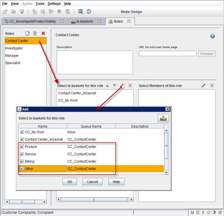
Figure 12-31 Adding in-baskets to a role
18. Save, commit, and deploy the solution.
Test the changes as shown in Figure 12-32. All work items are showing up in the Contact Center in-basket.

Figure 12-32 Viewing the main in-basket of the Contact Center role
Figure 12-33 shows that only the work items of the Product category are showing in the Product in-basket.

Figure 12-33 Viewing the custom in-basket of the Contact Center role
You can create multiple in-baskets for a queue that can be added to a role. However, you cannot assign multiple roles to the same queue, as shown in Figure 12-34.

Figure 12-34 Restriction on assigning roles to queues
12.5.3 Showing process errors in Case Manager Client
The default error handling procedure for processes requires an IT administrator to view malfunction steps in the Process Administrator tool. However, it might be more convenient to view the errors in the Case Manager Client. Some errors might not require the deep technical capabilities that are available in the Process Administrator tool. This section describes how to show errors in the Case Manager Client to facilitate error handling.
A default Malfunction process map is associated with every workflow. This default process map can be overridden so that errors are shown in the Case Manager Client. To show process errors to a role in the Case Manager Client, complete the following steps:
1. Go to the configuration view:
a. From Case Manager Builder, select Customer Complaints solution, and select More Actions → Open Process Designer.
b. Select the case type Complaint and then select any of the task workflow. Click OK.
Because we are working on the solution configuration, we can select any of the task workflows, as shown in Figure 12-35.
Figure 12-35 Selecting the Complaint Case Type

Figure 12-36 Selecting Configuration for a solution
2. Complete the following steps to create a queue:
a. Right-click Work queues and select New.
b. For the queue name, enter Administration and click OK.
As shown in Figure 12-37, this queue is the queue that receives work items to process errors.
Figure 12-37 Creating the Administration queue
3. Complete the following steps to configure the queue:
a. Right-click Administration and select Properties.
b. Add system fields to be shown with an in-basket:
i. Click the System Fields tab.
ii. Select F_StepName under Available Items and use the green arrow to add it to Selected Items. For the example, we add F_StepName, but any others can be added as needed.
iii. Click OK.
The results are shown in Figure 12-38.
Figure 12-38 Adding a system property to the system fields on the new queue
c. Complete the following steps to add data fields to be shown with an in-basket:
i. Click the Data Fields tab.
ii. Click the Exposed Data Fields icon in the upper right.
iii. Add the properties of the solution to Selected Properties, as shown in Figure 12-39 on page 495. Click OK.

Figure 12-39 Adding solution properties to data fields on the new queue
d. You can manually add more data fields. Earlier, you created extra workflow data fields for the Verify Document task. Add those fields to the queue. Double-click the cell with a blank Field Name and enter the data fields that you defined. The result should look as shown in the example in Figure 12-40.

Figure 12-40 Adding the additional data fields to the new queue
4. Complete the following steps to create and configure an in-basket on this queue:
a. Click the In-baskets tab.
b. Click the Add icon.
c. Double-click the new in-basket name to rename it and enter Malfunction.
The new in-basket is added, as shown in Figure 12-41.
Figure 12-41 Adding a Malfunction in-basket
d. Go to the Create Columns and Labels tab.
e. Click the Add icon. In the example, select Show system fields.
f. Select the following data fields:
• CC_CaseNumber
• CC_CustomerName
• CC_CustomerNumber
• F_StepName
• F_Subject
• Workflow_DocCaseNumber
• Workflow_DocCustomerName
• Workflow_DocCustomerNumber
• Workflow_DocTitle
g. Rename the column label for each data field to be more readable. Then, use the up and down arrow icons to sort the columns in a logical sequence. The result is shown in Figure 12-42 on page 497.

Figure 12-42 Configuring the Malfunction in-basket on the Administration queue
h. Click OK in the queue properties window to close it and return to the solution configuration.
5. Open the Validate Document workflow and browse through the submaps to see the Malfunction submap. Notice that it is read only.
6. Complete the following steps to override and configure the Malfunction submap:
a. Click the Create Map icon, select Override Inherited Map, and click OK.
The Malfunction map is selected by default, as shown in Figure 12-43 on page 498.
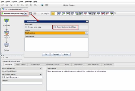
Figure 12-43 Creating a map to override the Malfunction map
b. Complete the following steps to modify the process of the Malfunction map:
i. Select the Review step.
ii. For the Step Name, enter Review Error.
iii. For the Activity Type, select the Administration work queue, as shown in Figure 12-44 on page 499.
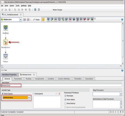
Figure 12-44 Configuring a step in the Malfunction map
c. This step must function within the Case Manager Client user interface so you must use an available Step page as your step processor. Click the General tab and select the step processor.
The example uses CC_CmAcmSTEP_DEFAULT_PAGE, as shown in Figure 12-45.

Figure 12-45 Selecting the default Step page
|
Tip: You might receive the following error about validation on deployment:
A step with a queue assigned to it should have a valid requested interface.
This error means that you have not set the Step Processor to a valid Step page. For every activity step in a solution, the Step Processor must be set to a registered Step page for the solution.
|
d. While you are in the Review Error step, select the Parameters tab. Move everything from Available Parameters other than SolutionIdentifier, as seen in Figure 12-46.

Figure 12-46 Exposed parameters of the Review Error step
e. Click the Routing tab. Add the two responses by double-clicking the empty cell under Name to edit a response and enter Skip. Enter Repeat for the second response.
The configured responses are shown in Figure 12-47.

Figure 12-47 Configured responses for the Review Error step
f. In the workflow map, create two return steps to replace the default system step. Right-click the existing Return system step and select Delete.
g. Make sure that the General System Palette is available, as shown in Figure 12-48. The palette menu is opened by clicking the arrow icon to the right of the available palette.

Figure 12-48 Available system palette
h. Drag the two return steps into the workflow, as shown in Figure 12-49.
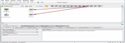
Figure 12-49 Adding two return steps after you remove the system step
i. Complete the following steps to rename each return step and set its expression:
i. Click the first Return step.
ii. Under the General tab, enter Return True for the Step Name.
iii. Enter true for the Return Expression.
iv. Click the second Return step.
v. Under the General tab, enter Return False for the Step Name.
Figure 12-50 Configured the return steps
For more information about how return values are used in a submap, see the IBM FileNet Information Center at this website:
7. Complete the following steps to create a route from the Review Error step to the Return True step:
a. On the route properties, enter Repeat for the Route.
b. Select Conditional Route under Routing.
c. Select ALL for the Condition.
d. Select Repeat for the Response.
e. Click ADD to create the condition.
The result should look as the example that is shown in Figure 12-51 on page 503.

Figure 12-51 Adding a conditional route that is based on a Repeat response
8. Create a route between the Review Error step and the Return False step. Enter Skip as the route name and set the response as Skip. The route configuration is shown in Figure 12-52.
Figure 12-52 Adding a conditional route that is based on a Skip response
9. Validate the workflow collection by clicking File → Validate Workflow Collection. The example workflow validation is successful as shown in Figure 12-53.

Figure 12-53 Validated workflow collection after you configure the Malfunction map
10. Save, commit, and deploy the solution.
Malfunctions now insert a work item into the Administrators queue. You can assign the Malfunction in-basket to any role. For more information, see 12.5.2, “Creating more in-baskets” on page 483. It can be an IT role or the Contact Center role in the example solution. This user can review the values and determine whether the step must be repeated (possibly with new values) or end and the workflow process continues.
As a brief example of this error handling, the following process might occur with the Verify Document task:
1. Add the Malfunction in-basket to the Contact Center role.
2. A document is added to a case as a Supporting Document with the following properties:
– Title: Bob's Attachment
– Case Number: C1600
– Customer Name: Bob
– Customer Number: 88489299
3. The Verify Document task is started.
4. A user in the Contact Center role sees the Verify Document work item.
5. The user determines that the content is not relevant.
6. For some reason, the user removes the document from the attachments by using the attachments widget. The user then clicks Remove Document.
7. An error occurs because the system has a null value for the Document attachment. The CE_Operations cannot move a null object.
8. An advanced user in the Contact Center role sees a work item in the Malfunction in-basket, as shown in Figure 12-54.

Figure 12-54 Work item in an in-basket because of error
9. This advanced user notices that an attachment is missing. The user adds the document in the case, Bob’s Attachment, back to the attachment, as shown in Figure 12-55.

Figure 12-55 Adding a document from the case as a workflow attachment
10. The advanced user believes that this action fixes the problem and selects the Repeat response so that the CE_Operations can try again.
11. The document is confirmed as moved out of the case.
..................Content has been hidden....................
You can't read the all page of ebook, please click here login for view all page.