
Chapter 26. Tap Aggregation
Often called “TapAgg” by the Arista team, this feature is the direct result of the amazing hardware design of Arista switches coupled with some brilliant software engineering.
Note
Fan-boy much? Read on, and if you don’t agree that this is great, I’ll buy you lunch. Actually, that’s not true; I won’t buy you lunch. I’ll buy myself lunch, though, and raise a toast in your name. Actually, I don’t really drink, so I won’t do that either.
Tap aggregation is the ability to connect multiple devices to a sniffer or analyzer or even groups of tools. Because good analyzers are generally very expensive and most important network devices reside in remote data centers, the ability to aggregate and control the connections to the devices has spawned an industry of tap aggregation devices. These devices tend to also be very expensive, but in the remote data centers, they can be a very valuable addition to the troubleshooting toolset of the networking team. If you’ve ever struggled with the problem of needing to monitor the traffic on one switch while the dedicated sniffer is attached to another switch—thus resulting in you driving to the data center to move a cable—tap aggregation is for you.
Arista primarily sells switches (though it has broadened what switches can do), so why is it involved in the realm of tap aggregation? Arista switches weren’t designed to be tap aggregation devices, but somewhere along the lines, someone discovered that because the switches are completely nonblocking, they can be easily configured to perform the same function as a tap aggregation device. Not only that, but they can do the same job as an expensive tap aggregation device for a fraction of the cost. Although tap aggregators tend to be expensive, tap aggregators capable of delivering 10 Gbps ports are often prohibitively so.
Warning
A quick warning is probably warranted. This feature essentially disables normal switching on the device. Do not experiment with this feature on a production switch! Doing so will likely result in bad things happening, such as the termination of your employment.
Let’s configure a 7280R for tap aggregation, which should explain some of the details for this feature. First, we need to put the switch into tap aggregation mode:
Arista(config)#tap aggregation
Arista(config-tap-agg)#mode exclusive
The only mode available on this switch is exclusive. On a 7500R or other tap aggregation–capable chassis switch, you can enable hybrid or mixed mode and enable certain blades to be tap aggregation devices while leaving the other blades to continue operating as normal:
Arista-7508R(config)#tap aggregation
Arista-7508R(config-tap-agg)#mode mixed module linecard 3-4,6
When this is done, assuming no preexisting tap aggregation configuration exists, all of the ports on the switch (or linecard) are placed into errdisabled mode. Back on our 7280R, here’s what the interfaces look like:
Arista#sho int status
Port       Name     Status       Vlan        Duplex  Speed Type
Et1                 errdisabled  1             full    10G 10GBASE-SRL
Et2                 errdisabled  1             full    10G 10GBASE-SRL
Et3                 errdisabled  1             full    10G 10GBASE-SRL
Et4                 errdisabled  1             full    10G 10GBASE-SR
Et5                 errdisabled  1             full    10G Not Present
Et6                 errdisabled  1             full    10G Not Present
Et7                 errdisabled  1           a-full  a-10G Not Present
Et8                 errdisabled  1             full    10G Not Present
[-- snip --]
To disable tap-aggregation mode, simply negate the tap aggregation command:
Arista(config)#no tap aggregation
We’re not going to do that now, though, because we’re trying to learn about this feature and disabling it would be counterproductive to that end.
When the switch is put into tap aggregation mode, it essentially stops functioning as a switch. Specifically, CPU-generated packets such as Spanning Tree Protocol (STP), Link Layer Discovery Protocol (LLDP), and the like are no longer sent to tool ports. Features such as Internet Group Management Protocol (IGMP) snooping and LLDP are prevented from running on tap or tool ports, though they remain running because future code revisions might allow hybrid mode. Arista recommends disabling these protocols when running in tap aggregation mode. Features such as Access Control Lists (ACLs), quality of service (QoS), and Link Aggregation Groups (LAGs) remain enabled since they may be of use with tap aggregation.
Ports on the switch can now be placed into one of two modes: tap or tool:
- tap
- A tap port is a port connected to either a tap device or a monitor port on a switch (or any other device delivering packets destined for a sniffer or analyzer). A tap port receives traffic.
- tool
- A tool port is one to which a sniffer or analyzer is usually connected. This is not always the case, as the destination may be another tap aggregation device, as you’ll see later in this chapter. A tool port sends traffic.
Tap and tool ports are associated through the use of an agg-group. A tool port can belong to multiple agg-groups, but a tap port can belong to only one. This allows a source to be sent to multiple analyzers, if so desired. Tap and tool ports can be physical interfaces or port channels.
To configure a port as a tool port, use the switchport mode tool interface command:
Arista(confi)#int e10
Arista(config-if-Et10)#switchport mode tool
To configure a port as a tap port, use the switchport mode tap interface command:
Arista(config-if-Et10)#int e11
Arista(config-if-Et11)#switchport mode tap
These changes are reflected in the output of show interface status:
Arista#sho int status
Port       Name     Status       Vlan        Duplex  Speed Type
Et1                 errdisabled  1             full    10G 10GBASE-SRL
Et2                 errdisabled  1             full    10G 10GBASE-SRL
Et3                 errdisabled  1             full    10G 10GBASE-SRL
Et4                 errdisabled  1             full    10G 10GBASE-SR
Et5                 errdisabled  1             full    10G Not Present
Et6                 errdisabled  1             full    10G Not Present
Et7                 errdisabled  1           a-full  a-10G Not Present
Et8                 errdisabled  1             full    10G Not Present
Et9                 errdisabled  1             full    10G Not Present
Et10                errdisabled  tool          full    10G Not Present
Et11                errdisabled  tap           full    10G Not Present
[-- snip --]
Note
When interfaces are placed into tap or tool mode, normal Ethernet learning and flooding behavior is disabled. This helps to ensure that the tap ports remain RX-only and the tool ports remain TX-only. Additionally, Layer 2 and Layer 3 protocols are prevented from sending protocol packets to tap and tool ports.
For our tap aggregation ports to be of any use, we need to add them to an aggregation group. This is done a little differently based on the port type configured. To better illustrate this, I’ve added one more of each type of port. Here is how the ports are configured, as shown by the output of show interface status with some grepping in the interest of brevity:
Arista#sho int status | egrep 'tap|tool'
Et10               notconnect   tool          full    10G Not Present
Et11               notconnect   tap           full    10G Not Present
Et12               notconnect   tap           full    10G Not Present
Et13               notconnect   tap           auto   auto 1000BASE-T
Et20               notconnect   tool          full    10G Not Present
Et21               notconnect   tap           full    10G 10GBASE-SRL
Et22               notconnect   tap           full    10G Not Present
Et23               connected    tap           full    10G 10GBASE-SRL
Given this configuration, I would like to have interfaces Et11, 12, and 13 forward their packets to the tool connected to interface Et10, whereas the interfaces Et21, 22, and 23 should forward their packets to the tool at interface Et20. Grammatically, I should probably have written that the interfaces should forward their packets to the tool connected to the respective interfaces, but the image of a guy I’d describe as a “tool” sitting in front of whatever device he’s using to capture packets makes me giggle. Grouping all of the 1x ports together and all of the 2x ports together tickles my OCD, and humor helps to take the edge off.
Tool ports can be included in multiple groups, whereas tap ports cannot. Let’s get the more complicated possibility out of the way first and look at a tool port:
Arista(config-if-Et10)#switchport tool group ?
  add     Add groups to the current list
  remove  Remove groups from the current list
  set     Set groups for the interface
I’ll add two groups, called Sniffer and Analyzer. Port Et10 will have the Sniffer, and E20 will have the Analyzer.
Arista(config-if-Et10)#switchport tool group set Sniffer
Here’s the configuration for Et20:
Arista(config-if-Et10)#int e20
Arista(config-if-Et20)#switchport tool group set Analyzer
Tap ports are configured a little bit differently. To configure ports Et11 through 13 to belong in the Sniffer group, I use the switchport tap interface command:
Arista(config-if-Et11-13)#switchport tap ?
  allowed     Configure allowed vlans when interface is in tap mode
  default     Configure default tap group
  identity    Configure tap port id
  native      set native vlan when interface is in tap mode
  truncation  Configure if ingress packet should be truncated
We’ll look at the other options in a bit. For now, we use the default group option:
Arista(config)#int e11-13
Arista(config-if-Et11-13)#switchport tap default group Sniffer
Now let’s do the same for ports Et21 through 23, placing them into the Analyzer group:
Arista(config-if-Et11-13)#int e21-23
Arista(config-if-Et21-23)#switchport tap default group Analyzer
To see the current status of the tap aggregation groups, use the show tap aggregation groups command:
Arista#sho tap aggregation groups
Group Name                          Tool Members
--------------------------------------------------------------------
Sniffer                             None
Analyzer                            None

Group Name                          Tap Members
--------------------------------------------------------------------
Sniffer                             None
Analyzer                            Et23
Where are all of the interfaces we just configured? They’re not reported here because they’re not currently connected. Look back to the show interface status command a few paragraphs back. See how only one interface is connected? That’s the one that shows up now. This can be a little confusing if you’re not familiar with how the feature works, but just remember that this is showing active ports, not configured ports. The command is reporting that there are no tool members for either group because there are no active tool members in either group. Let’s see what happens when I connect up ports Et10 through 13:
Arista#sho tap aggregation groups
Group Name                          Tool Members
--------------------------------------------------------------------
Sniffer                             Et10
Analyzer                            None


Group Name                          Tap Members
--------------------------------------------------------------------
Sniffer                             Et11, Et12, Et13
Analyzer                            Et23
That’s a little better! Let’s see it in action.
Tap Aggregation from the Command-Line Interface
Figure 26-1 presents the lab scenario that I’ve built to show how we can use groups to affect the flow of traffic in a tap aggregation switch.
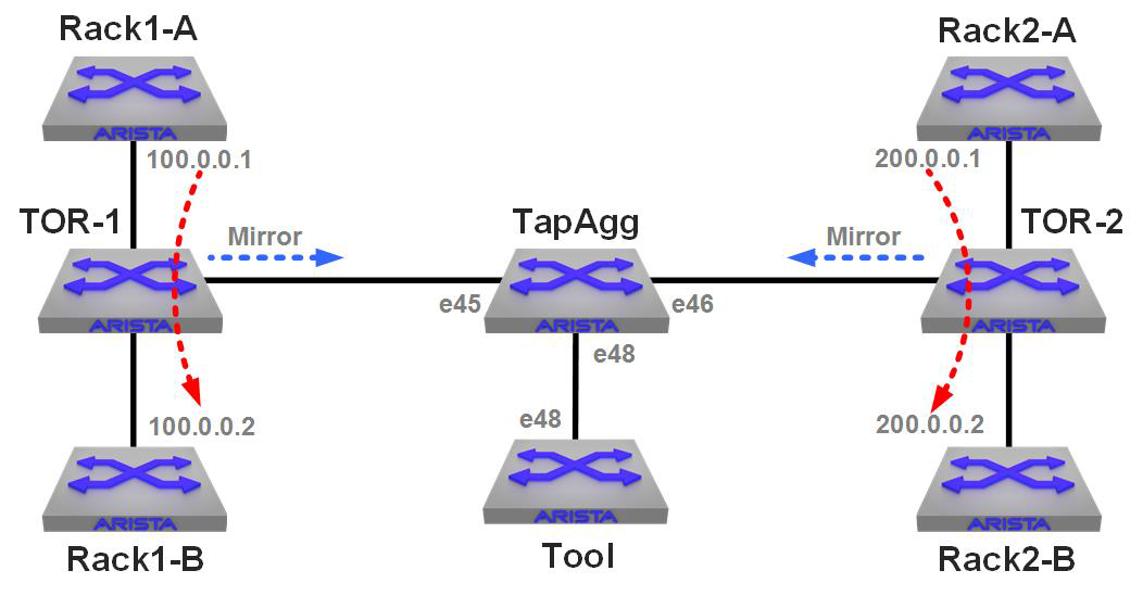
Figure 26-1. A tap aggregation lab
There are two “racks” in this lab: Rack1 and Rack2. Each of the “A” switches have a continuous ping running to the “B” switch in that rack. Each of the Top-of-Rack (ToR) switches have a VLAN connecting them and a mirror session configured with a filter that allows only the ping traffic to be mirrored. Both of the TOR switches have their mirror destinations set to the TapAgg switch in the middle.
The Tool device on the bottom is an Arista switch, and all I’m doing there is a tcpdump of interface e48.
Here’s the relevant configuration on the TapAgg switch:
tap aggregation
   mode exclusive
!
interface Ethernet45
   description TOR-1
   switchport mode tap
   switchport tap default group Rack1
!
interface Ethernet46
   description TOR-2
   switchport mode tap
   switchport tap default group Rack2
!
interface Ethernet48
   description TapAgg Tool
   switchport mode tool
   switchport tool group set Rack1 Rack2
The link to TOR-1 is in the group Rack-1, the link to TOR-2 is in the group Rack-2, and the tool port (e48) is in both groups.
The tool switch has the following monitor configured:
monitor session GAD source Ethernet48 rx
monitor session GAD destination Cpu
Running the command tcpdump –c 5 –q –i mirror0 (capture five packets with quiet output on int e48) on the tool switch yields the following:
[admin@Tool ~]$ tcpdump -c 5 -q -i mirror0
tcpdump: WARNING: mirror0: no IPv4 address assigned
tcpdump: verbose output suppressed, use -v or -vv for full protocol
 decode
listening on mirror0, link-type EN10MB (Ethernet), capture size
 65535 bytes
14:08:28.961608 28:99:3a:be:9f:92 (oui Unknown) > 28:99:3a:be:9d:d6
 (oui Unknown), IPv4, length 98: 100.0.0.1 > 100.0.0.2: ICMP echo
 request, id 12207, seq 1068, length 64
14:08:29.507166 28:99:3a:be:9e:20 (oui Unknown) > 28:99:3a:be:a0:70
 (oui Unknown), IPv4, length 98: 200.0.0.1 > 200.0.0.2: ICMP echo
 request, id 4323, seq 702, length 64
14:08:29.961603 28:99:3a:be:9f:92 (oui Unknown) > 28:99:3a:be:9d:d6
 (oui Unknown), IPv4, length 98: 100.0.0.1 > 100.0.0.2: ICMP echo
 request, id 12207, seq 1069, length 64
14:08:30.507178 28:99:3a:be:9e:20 (oui Unknown) > 28:99:3a:be:a0:70
 (oui Unknown), IPv4, length 98: 200.0.0.1 > 200.0.0.2: ICMP echo
 request, id 4323, seq 703, length 64
14:08:30.961590 28:99:3a:be:9f:92 (oui Unknown) > 28:99:3a:be:9d:d6
 (oui Unknown), IPv4, length 98: 100.0.0.1 > 100.0.0.2: ICMP echo
 request, id 12207, seq 1070, length 64
5 packets captured
5 packets received by filter
0 packets dropped by kernel
Looking at the destination IP addresses that I’ve put in bold, you can see that the Tool switch is receiving packets from the continuous ping in Rack1 and from Rack2.
Now, I go into the TapAgg switch and remove the group Rack2 from the tool port:
TapAgg(config-if-Et48)#no switchport tool group Rack2
Running the same tcpdump on the Tool switch yields the following:
[admin@Tool ~]$ tcpdump -c 5 -q -i mirror0
tcpdump: WARNING: mirror0: no IPv4 address assigned
tcpdump: verbose output suppressed, use -v or -vv for full protocol
 decode
listening on mirror0, link-type EN10MB (Ethernet), capture size 65535
 bytes
14:13:11.958902 28:99:3a:be:9f:92 (oui Unknown) > 28:99:3a:be:9d:d6
 (oui Unknown), IPv4, length 98: 100.0.0.1 > 100.0.0.2: ICMP echo
 request, id 12207, seq 1351, length 64
14:13:12.958897 28:99:3a:be:9f:92 (oui Unknown) > 28:99:3a:be:9d:d6
 (oui Unknown), IPv4, length 98: 100.0.0.1 > 100.0.0.2: ICMP echo
 request, id 12207, seq 1352, length 64
14:13:13.958886 28:99:3a:be:9f:92 (oui Unknown) > 28:99:3a:be:9d:d6
 (oui Unknown), IPv4, length 98: 100.0.0.1 > 100.0.0.2: ICMP echo
 request, id 12207, seq 1353, length 64
14:13:14.958879 28:99:3a:be:9f:92 (oui Unknown) > 28:99:3a:be:9d:d6
 (oui Unknown), IPv4, length 98: 100.0.0.1 > 100.0.0.2: ICMP echo
 request, id 12207, seq 1354, length 64
14:13:15.958864 28:99:3a:be:9f:92 (oui Unknown) > 28:99:3a:be:9d:d6
 (oui Unknown), IPv4, length 98: 100.0.0.1 > 100.0.0.2: ICMP echo
 request, id 12207, seq 1355, length 64
5 packets captured
5 packets received by filter
0 packets dropped by kernel
Now, let’s remove the Rack1 group and replace it with Rack2:
TapAgg(config-if-Et48)#no switchport tool group Rack1
TapAgg(config-if-Et48)#switchport tool group Rack2
As you’d expect, now we get only the pings from the other rack:
[admin@Tool ~]$ tcpdump -c 5 -q -i mirror0
tcpdump: WARNING: mirror0: no IPv4 address assigned
tcpdump: verbose output suppressed, use -v or -vv for full protocol
 decode
listening on mirror0, link-type EN10MB (Ethernet), capture size 65535
 bytes
14:16:53.507598 28:99:3a:be:9e:20 (oui Unknown) > 28:99:3a:be:a0:70
 (oui Unknown), IPv4, length 98: 200.0.0.1 > 200.0.0.2: ICMP echo
 request, id 4323, seq 1206, length 64
14:16:54.507605 28:99:3a:be:9e:20 (oui Unknown) > 28:99:3a:be:a0:70
 (oui Unknown), IPv4, length 98: 200.0.0.1 > 200.0.0.2: ICMP echo
 request, id 4323, seq 1207, length 64
14:16:55.507599 28:99:3a:be:9e:20 (oui Unknown) > 28:99:3a:be:a0:70
 (oui Unknown), IPv4, length 98: 200.0.0.1 > 200.0.0.2: ICMP echo
 request, id 4323, seq 1208, length 64
14:16:56.507595 28:99:3a:be:9e:20 (oui Unknown) > 28:99:3a:be:a0:70
 (oui Unknown), IPv4, length 98: 200.0.0.1 > 200.0.0.2: ICMP echo
 request, id 4323, seq 1209, length 64
14:16:57.507616 28:99:3a:be:9e:20 (oui Unknown) > 28:99:3a:be:a0:70
 (oui Unknown), IPv4, length 98: 200.0.0.1 > 200.0.0.2: ICMP echo
 request, id 4323, seq 1210, length 64
5 packets captured
5 packets received by filter
0 packets dropped by kernel
This is very useful, but the simple truth is that most people today don’t use tap aggregation from the command-line interface (CLI), preferring instead to use the built-in graphical user interface (GUI) or CloudVision (more on that in a moment). I think using it through the CLI is a great thing to know how to do because web access or CloudVision is not always available in the field.
The TapAgg GUI
Using the CLI is a great thing to know, and I honestly just scratched the surface of what’s possible. What most people who are using tap aggregation on an Arista switch do is use the TapAgg GUI.
When tap aggregation is enabled, a website is spun up on the switch that you can go to with your favorite web browser (assuming it’s reasonably current) that allows you to configure the feature with a nice graphical interface. On our switch, given the last state I left it, that GUI looks like what you see in Figure 26-2.
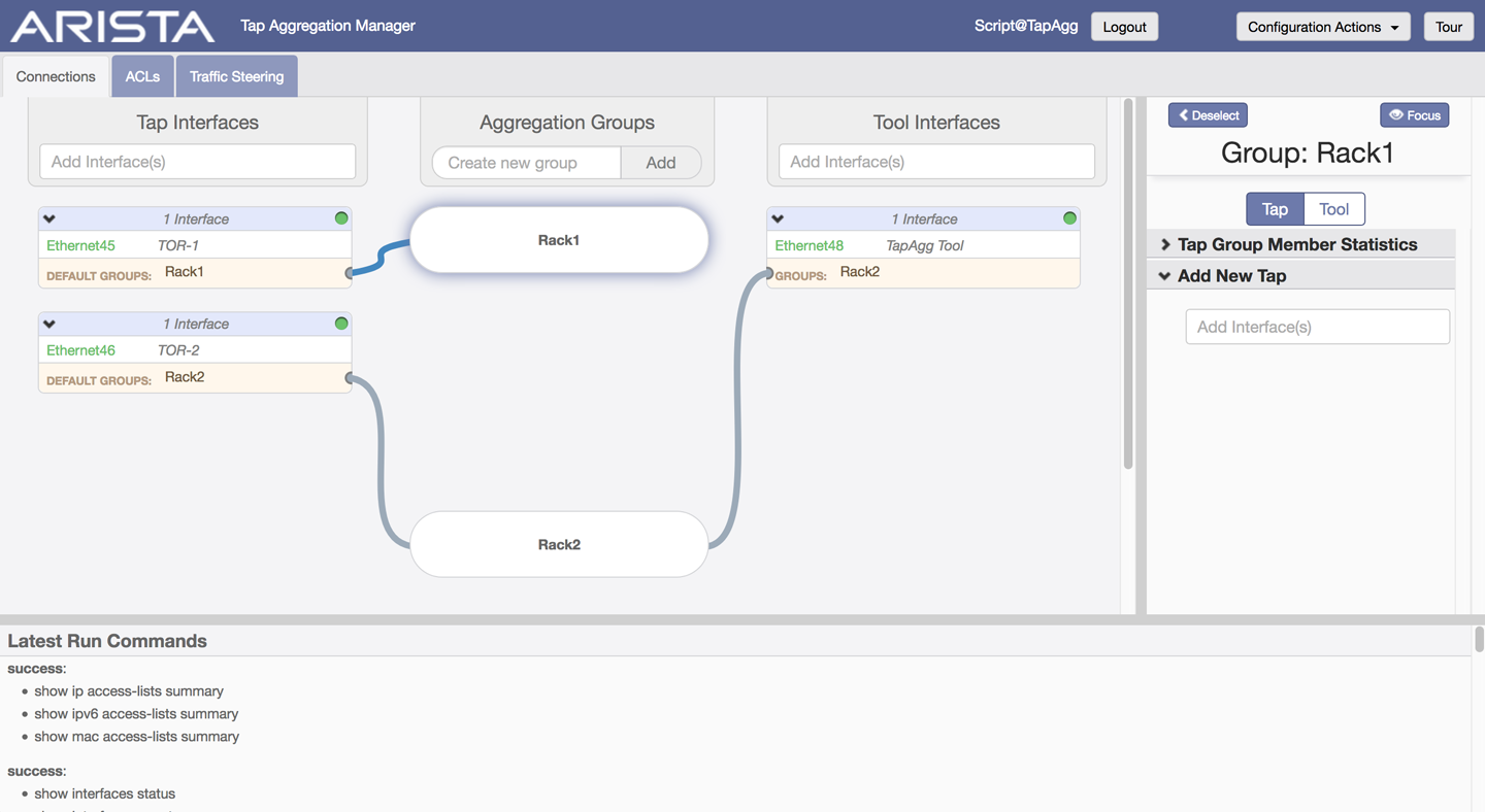
Figure 26-2. The TapAgg GUI
The TapAgg GUI shows a very nice visual representation of what we’ve configured and also hints at the fact that we can configure ACLs and Traffic Steering, though I’m not going to go into that level of detail in this book. Of course, the TapAgg GUI is also available through CloudVision if you have tap aggregation enabled on any CloudVision-controlled devices.
Conclusion
Tap aggregation mode is a powerful tool, but remember, on a fixed-configuration switch that it disables normal switching functions for the entire device. On modular switches you can enable individual blades as tap aggregation devices while the rest of the switch remains for your switching pleasure.