Chapter 2. Network Designs
Arista changed the world of networking in more ways than just groundbreaking new products. Seeing a change in the needs of large-scale data centers, Arista promoted the use of some new network design scenarios that have become the standard for many of the Cloud Titans. Those designs have become so successful that they’ve been adopted by many smaller networks, as well. Why? Mostly because the old designs were laden with complexity as a result of their introduction decades ago when there was no way to avoid such things. Modern networks are much more powerful and, as a result, can be much simpler, though in my experience there is no end to the complexity that a determined network engineer can add.
Remember that these are design principles and they might not apply to every situation. Still, using these designs as a starting point can help immensely when designing new layouts from scratch. Oh, and you’ll never see me use terms like greenfield unless it’s ironically, because I consider that business-speak, and if there’s one thing that will make me cross-eyed, it’s a nice dose of business-speak. I’d like to spitball a greenfield design so we can shift the paradigm in order to leverage our core competencies in a forward-thinking way that’s a win-win solution without boiling the ocean. We’ll all need to give 110% as we take it to the next level so we can maximize impact while penetrating multiple demographics. It is what it is.
George Orwell would be proud.
At any rate, there was a valid need for rethinking network designs because the commonly used three-tier architecture was conceived when the majority of the traffic into and out of the data center was what is commonly called north-south. Remember the whole core-distribution-access design? That was in three tiers because a request would come in from the top, go down south to the next layer where it would be answered, and then sent down a layer to be distributed down to the final layer where it would be worked on, after which the reply would be sent back north up the tiers and back to the source. In a world in which routers were expensive standalone devices that were separated by firewalls and switches (and where virtual machines did not yet exist) this three-tier architecture made a lot of sense.
Decades later, almost everything has changed, so the network designs had to change, too. Let’s take a look at some of the network designs that are commonly recommended by Arista.
Bow Tie MLAG
When it comes to phrases that make me squirm, one that’s high on my list is Bow Tie MLAG. MLAG is the open-standard term for Multi-Chassis Link Aggregation Group (see Chapter 18), but that’s not the part of the phrase that bugs me. Yes, I know, the design looks like a bow tie. You know, if you remove some of the links and apply a bit of imagination. Maybe it’s just my dislike of bow ties (or any tie, really) that offends me. I therefore propose a new name. How about, It’s not a freaking bow tie MLAG? Too long? Black Widow MLAG! Honestly, I’ve got nothing better than Bow Tie MLAG, so I guess it stays. If you see me mumbling incoherently in a corner somewhere, it’s probably due to me having to say Bow Tie MLAG repeatedly.
Figure 2-1 shows a very simple drawing of a Bow Tie MLAG. This is a Layer 2 design where the top two switches form an MLAG pair and the bottom two also form an MLAG pair. Either pair can be from another vendor’s solution such as Cisco’s VPC, but so long as there’s MLAG involved, we can use the delightful moniker Bow Tie MLAG with reckless abandon. For more information on MLAGs and how to create your own Bow Tie (grumble), see Chapter 18.

Figure 2-1. Bow Tie MLAG
Leaf-Spine
You might hear this referred to as Spine-Leaf or Leaf-Spine depending on who’s saying or writing it. Regardless of how it’s referenced, there are Spines, and there are Leaves, though that’s the pedant in me needing to pluralize the word leaf as leaves. When speaking with network engineers, you might hear the term leafs, which I can’t decide is an application of plurality for a new word that has nothing to do with trees, or if it’s wrong because the plural of the word leaf has always been leaves. This is just one more example of why I can’t sleep most nights.
This design is based on something called a Clos network, which was developed in the 1950s by Charles Clos. The principles of the Clos network have been used in telephony for decades and are also used in Application-Specific Integrated Circuit (ASIC) design. The Clos design principles were used in technologies such as Inifiniband where director switches contained a two-level fat tree (Clos-3) network internally, which included the concept of Leaf modules and Spine modules. Arista pioneered the terms for use in Ethernet starting around 2008 or so, and the rest, as they say, is history.
Figure 2-2 shows a simplified Leaf-Spine architecture with four Spine switches on the top of the drawing and six Leaf switches on the bottom.
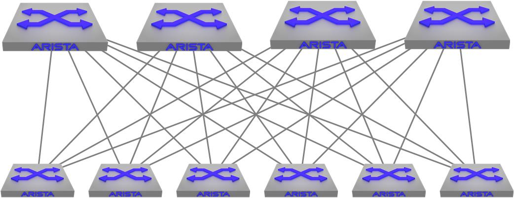
Figure 2-2. Spine-Leaf network design
Originally, Spine switches were larger and more powerful and were analogous to the older core switches in the three-tier architecture in that they’re the way that all other devices connect to one another, but there’s a lot more to it than that, which is why Arista doesn’t call them cores. These days, spine switches are generally just higher-density devices thanks to the advent of devices like 32-port 100 Gbit switches.
Leaf switches are commonly top-of-rack (ToR) switches, and they are connected to all of the Spines. This creates a type of fabric between the Leaf and Spine layers where the distance from any ToR switch to any other ToR switch is only one hop. Not only that, but the Spine layer can suffer many device outages while still maintaining that one-hop distance.
Years ago, there was a lot of talk of protocols like TRansparent Interconnection of Lots of Links (TRILL), which was a way of creating a similar network using Layer 2 (L2) protocols. The Leaf-Spine architecture is different in that it is generally built using Layer 3 (L3) protocols such as Open Shortest Path First (OSPF) or Intermediate System to Intermediate System (IS-IS), but Border Gateway Protocol (BGP) seems to be the winner for a variety of reasons.
Why L3 instead of L2? There used to be a rule in networking that said, “switch when you can; route when you have to.” This rule existed because switching was fast and routing was slow, but with the advent of route forwarding being done in ASIC hardware, that rule is no longer valid. In fact, I’ve been to many customers where they have moved away from L2 entirely opting instead to do L3 right down to the server.
This is all made possible through the addition of something called Equal-Cost MultiPathing (ECMP). With ECMP enabled using BGP (for example), not only are their four paths from each Leaf switch, but all of them are equally desirable through the use of hashing. Now, not only are there many paths for redundancy, but those paths are all active making the entire Leaf-Spine architecture resilient while also being highly utilized. This was (and still is) a game-changer in the world of Ethernet networking because the limitation of a single best path had been significantly improved. As you’ll see, this concept is also expanded upon in other designs.
How many Spines can you have in a Leaf-Spine network? That depends on the hardware in use. Looking at the Arista 7500R switch data sheet, it is capable of 128-way ECMP, so each Leaf could connect to 128 Spine switches. That’s a crazy-wide topology, and if you do the math, that’s a lot of math. Luckily Arista sells 16-slot 7500Rs that support 2,304 10 Gbps ports, so that should be enough ports. For now.
Note
I joke about 2,304 ports being enough for now because Arista continues to blow me away with escalating hardware capacities, so it wouldn’t surprise me to see that number increase in ways that I couldn’t imagine. I remember buying one of the first Kalpana switches with eight ports of 10 Meg (MEG!) Ethernet. When I wrote the first edition of Arista Warrior, 40 Gbps was a big deal and now there are Arista switches that support over 500 ports of 100 Gbps. 400 Gbps and 800 Gbps are now the new hotness. I can only write so fast!
You might see the terms Leaf and Spine used when people talk about MLAG designs, and that’s because anything on the top layer has generically become a Spine, whereas anything on the bottom layer has generically become a Leaf. Whether this is correct doesn’t really matter so long as whoever is communicating is making sense.
Spline
In the old days, we had something called a collapsed core design in which the core and distribution layers were collapsed because who needs three damn layers of networks, anyway? Thinking in a similar vein, the concept of collapsing the Spine and Leaf layers together is called a Spline network, which you can see in Figure 2-3—and, yes, Arista has trademarked that term, no doubt having been collectively annoyed that the entire industry has adopted the phrase Leaf-Spine without giving them credit.

Figure 2-3. Spline network
A Spline network is basically one in which all of the servers (and whatever else) connect to two or more Arista switches. It’s a Leaf-Spine network without any Leafs, or to be more accurate, the Spine switches (which don’t usually connect to servers) are connecting to servers and are therefore also acting as Leafs. As one of my favorite tech-reviewers commented, “That sounds stupid,” which made me laugh so hard that I needed to keep it while also commenting on it. Consider this design to be more like an End-of-Row (EoR) design in which all of the servers in the row connect to a pair of switches at the end of the row. Anyway, because we’ve mashed the Leafs and Spines together, we get the portmanteau Spline.
A Spline network is probably more of an enterprise type of design, though there’s no reason it can’t be used anywhere that the scale of a full Leaf-Spine topology is unnecessary or not cost effective.
VXLAN/Overlay
Virtual Extensible LAN (VXLAN) (covered in Chapter 21) is a means of building an L2 overlay network on top of an existing L3 underlay network. Essentially L2 tunnels are built on top of an existing L3 topology. In the case of Figure 2-4, there are two VXLAN Segments shown (dotted lines) riding on top of the existing Leaf-Spine network.

Figure 2-4. VXLAN overlay network
For reasons outlined in Chapter 21, this design is becoming more and more common. I’ve seen it within rows, within data centers, between data centers, and even over the internet (though that didn’t work well for them), so it’s pretty much everywhere these days.
Universal Spine
All of these network designs are great, but what if you have a complex network spanning multiple locations, or even multiple rows in a massive data center, each with its own potentially different network design? Enter the Universal Spine.
Figure 2-5 shows each of the previously mentioned network designs along the bottom with each of them connected to a new Universal Spine network, in this case comprising Arista Chassis switches. And yes, it took me a long damn time to connect all those links.

Figure 2-5. Universal Spine
With the ability to do wire-speed switching and routing in hardware and the ability to support massive route tables and huge ECMP, the Universal Spine allows the connection of disparate network topologies with one another and to the rest of the world, as well. Don’t forget that this Universal Spine can also be connecting any number of cloud solutions including public and private clouds with services like Amazon Web Services (AWS), Microsoft Azure, and the like, all competing for your networking dollars.
AnyCloud
AnyCloud is essentially the ability to connect your Arista networks to a cloud-based environment using vEOS-Router while also incorporating security through a Virtual Private Network (VPN). With the widespread adoption of solutions like AWS and Microsoft Azure, many networks are now fully involved in something Arista calls the Hybrid Cloud architecture. Your network might have local devices, cloud devices, virtual cloud devices, and who knows what else. AnyCloud allows you to connect them all. Of course, you can manage it all with Cloudvision, too.
Conclusion
These descriptions are clearly only high-level overviews of each of the topologies listed. Details of how to build them all is spread throughout this book, but having an understanding of what each of these designs was created for will help you when you’re discussing design scenarios for the modern data center, campus, or enterprise network.