
CHAPTER 3
Using Drawing Aids
The drawing aids in the AutoCAD® program are like the triangles, compasses, and engineering scales of traditional drafting. Drawing aids are essential modes and methods of entering data that, once mastered, allow you to create measured drawings with ease. I highly recommend learning all of the drawing aids because they will make you a more productive draftsperson. Most drawing aids can be toggled on or off from the application status bar. Additional settings and dialog boxes are accessible by right-clicking the individual status bar toggles.
In this chapter, you’ll learn to do the following:
- Use Grid and Snap
- Employ Ortho and Polar Tracking
- Use PolarSnap
- Select running object snaps
- Harness the From snap
- Apply object snap tracking
Use Grid and Snap
![]()
The most basic drawing aid, Grid, makes the canvas in AutoCAD look like graph paper. You can adjust the grid’s measured size and the spacing of its major lines to simulate many types of graph paper.
Snap constrains your ability to draw objects so that they automatically start and end precisely at grid intersections. Grid and Snap are most helpful when used together so that you can draw objects that snap to the grid. Figure 3.1 shows some of the status bar toggles you’ll be learning about in this chapter.
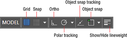
FIGURE 3.1 Various status toggles
Exercise 3.1: Draw with Grid and Snap
In the following steps, you will experiment with Grid and Snap by drawing lines using these aids:
![]()
- Click the New button on the Quick Access toolbar.
- Choose the acad.dwt template (or acadiso.dwt metric template) from the Select Template dialog box and click Open.

Open the Customization menu (on the extreme right of the status bar) and select Units and LineWeight. Deselect Isometric Drafting, Annotation Visibility, Autoscale, and Annotation Scale. Click in the drawing window to close the Customization menu. Change Units to Architectural if you are using Imperial units; leave Decimal selected if you are using metric units.
- Type DS and press Enter to open the Drafting Settings dialog box. Change Grid X spacing to 1" (or 10 for metric) and press Tab; Grid Y spacing updates with the same value. Set Major Line Every to 12 for Imperial (or 10 for metric) so that you’ll see darker grid lines every foot. Notice that Snap spacing is set to 1/2" (or 10 mm) by default. Select Snap On and verify that the Grid Snap and Rectangular Snap radio buttons are selected in the Snap Type area (see Figure 3.2). Click OK.

FIGURE 3.2 Setting up grid spacing and toggling on Snap

- Click the Line tool in the Draw panel on the ribbon’s Home tab. Click the first point close to the origin point of the UCS icon, located in the lower-left corner of the drawing window. Click the second point, 2' (or 600 in metric) above the first point, by clicking the second intersection (or sixth intersection in metric) of major grid lines. Right-click to end the LINE command.

- Click the Lineweight icon in the status bar so that the button is highlighted in blue.
- Right-click the Lineweight icon, and choose Lineweight Settings from the context menu. Open the Default drop-down list, select 0.012" (or 0.30 mm) (see Figure 3.3), and click OK.

FIGURE 3.3 Adjusting the default lineweight settings
- Type L and press Enter twice to continue drawing from the last point. Toggle Grid off in the status bar. Move the cursor horizontally to the right from the point at which the rubber band is anchored. Click the drawing canvas when the dynamic input value reads 2'-0" (or 600 mm), as shown in Figure 3.4, and press Enter.
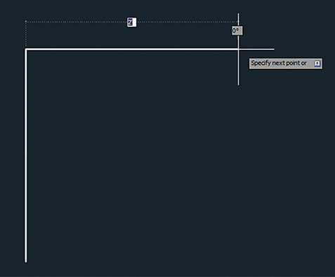
FIGURE 3.4 Using Snap to gauge distances without typing specific measurements
- Save your work.
Your model should now resemble Ex03.1-end.dwg, which is available among this chapter’s companion files.
Employ Ortho and Polar Tracking
Ortho mode aids in drawing orthogonal (horizontal or vertical) lines. Polar Tracking is more flexible than Ortho mode, with the ability to constrain lines to increments of a set angle. A list of common angles—45, 90, 135, 180, and so on—is included on Polar Tracking’s context menu. The traditional square and a set of triangles from traditional drafting are analogs to Ortho and Polar Tracking modes in AutoCAD.
Exercise 3.2: Draw with Ortho and Polar Tracking
Let’s try Ortho and Polar Tracking modes by drawing a series of line segments. You’ll use Ortho when the segments are 90° apart and Polar Tracking when the segments are drawn at other angles. Begin by opening the file Ex03.2-start.dwg from this chapter’s companion files.
- Type L, position the cursor over the right endpoint of the horizontal line, and click to establish the first point of a new line.
- Toggle off Snap mode by pressing the F9 key.
Toggle on Ortho mode by clicking the Ortho toggle in the status bar or by pressing the F8 key.
- Move the cursor down from the last point, type 10-3/4" (or 240 for metric), and press Enter. Ortho mode constrains the line vertically, and typing in an explicit value obviates the need for Snap.

- Toggle off Ortho mode by clicking its status bar button. Toggle on Polar Tracking by clicking the adjacent button on the right. Right-click the Polar Tracking button, and choose 45°, 90°, 135°, 180° from the context menu.
- Move the cursor around and observe that green dashed lines appear in eight locations around a circle (in 45° increments). Move the cursor to the right relative to the last point, type 2' (or 600 for metric), and press Enter (see Figure 3.5). Press Esc to terminate the LINE command without deleting the last segment drawn.

FIGURE 3.5 Drawing a line using Ortho mode and direct distance entry
- Save your work.
Your model should now resemble Ex03.2-end.dwg, which is available among this chapter’s download files.
Just like Ortho mode, Polar Tracking guarantees that the last line drawn was perfectly aligned to the set increment; you merely had to move the cursor in the general direction you wanted to direct the new line. Ortho and Polar Tracking save you from having to type in angles or coordinate values explicitly or to even think about coordinate systems.
Use PolarSnap
PolarSnap includes a kind of snap that is customized for Polar Tracking. Instead of being tied to a spatial grid (as with Snap), PolarSnap is based on relative polar coordinates.
Exercise 3.3: Draw with PolarSnap
As you’ll see in the steps that follow, PolarSnap is useful for drawing measured lines on angles other than horizontal or vertical. Begin by opening the file Ex03.3-start.dwg from this chapter’s companion files.
![]()
- Toggle on Snap by clicking its icon on the status bar. Right-click the same button and choose Snap Settings from the context menu.
- Select the PolarSnap radio button in the Drafting Settings dialog box. Type 1" (or 10 for metric) in the Polar Distance text box (this dialog was shown in Figure 3.2). Click OK.
Type L and press Enter. Type 4',1'1-1/4 (or 1200,360 for metric) and press Enter to input the absolute coordinates of the end of the lower horizontal line.
- Move the cursor down at a 45° angle from east, and observe the Snap values that appear with Dynamic Input onscreen. Click when the value is 6" (or 150 mm) (see Figure 3.6).

FIGURE 3.6 Drawing a line using Polar Tracking and PolarSnap
- Move the cursor vertically down and click to draw a line when the value reads 1' (or 300 mm). Right-click to end the LINE command.
- Press the spacebar to repeat the LINE command. Type 0,0 (or 100,200 for metric) and press Enter to input the first endpoint of the new line.
- Toggle off Snap mode by clicking its icon on the status bar, thus disabling PolarSnap.
- Move the cursor horizontally to the right until it overshoots the last line drawn in step 5. Click to draw the line without worrying about its length (see Figure 3.7). Right-click to complete the command.

FIGURE 3.7 Drawing a horizontal line that overshoots the vertical line
- Type F (for Fillet) and press Enter. Verify that Radius is set to 0 in the Command window and then click the vertical and horizontal lines on the portions of the lines that you want to keep (marked A and B in Figure 3.8).

FIGURE 3.8 Filleting with a zero radius to form a corner
- Save your work.
Your model should now resemble Ex03.3-end.dwg, which is available among this chapter’s companion files.
Select Running Object Snaps
The lines you have drawn thus far are all precisely connected because they were chained together as they were drawn or their coordinates were known. Aside from these special circumstances, lines must be connected using object snaps to ensure accuracy.
You learned to use the Object Snap context menu in Chapter 2, “Gaining Basic Drawing Skills,” and now you will use that as a jumping-off point to learn a far more efficient method called running object snap.
Exercise 3.4: Draw with Running Object Snaps
As you will see in the steps that follow, with running object snaps, frequently used object snaps can be turned on continuously. That way, you don’t have to invoke them explicitly every time you want to use object snaps. Begin by opening the file Ex03.4-start.dwg from this chapter’s companion files.
- Using Polar Tracking, but without invoking Snap or Object Snap, draw a line using points A to B in Figure 3.9 as a guide. Click each point as accurately as you can because I want you to see that you can’t make it perfect without using Object Snap.
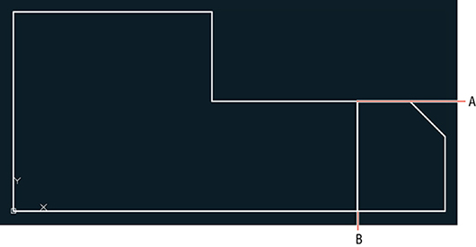
FIGURE 3.9 Drawing a line without Object Snap
- Press Z and then Enter. Click two points to define a tightly cropped zoom window around point A. Zoom in again if necessary until you can see that the endpoint of the line you just drew is not on the horizontal line (see Figure 3.10). No matter how carefully you clicked point A in the previous step, the line you drew will not be on the edge (it will either fall short of it or overshoot it).

FIGURE 3.10 Zooming in reveals that the lines do not meet.
- Select Zoom Previous from the Navigation bar’s Zoom menu. Click Zoom Previous again if necessary to return to the original view.
Click the line drawn in step 3, and press the Delete key.

- Toggle on Object Snap on the status bar. Right-click the same icon and choose Object Snap Settings from the context menu. Click the Clear All button and then select Endpoint, Midpoint, and Perpendicular (see Figure 3.11). Click OK.

FIGURE 3.11 Turning on a few Running Object Snap modes

- Toggle off Polar Tracking on the status bar. Click the Line tool on the Draw panel. Move the cursor close to point A in Figure 3.12 and wait for the green endpoint marker to appear. When it does, click to snap the first point of your line precisely to this point.

FIGURE 3.12 Drawing a line using running object snaps
- Move the cursor down to point B and wait until the green perpendicular marker appears. When it does, click the drawing canvas to select the second point of the line. Press Esc to end the command. This line is connected precisely at both ends because Object Snap was used.
- Zoom into point A or B in Figure 3.13 and verify that the lines are connected perfectly. Click Zoom Extents in the Navigation bar to return to the initial overall view.

FIGURE 3.13 Overriding running snaps with the Nearest snap
- Type L and press Enter. Hold down Shift, right-click to open the Object Snap context menu, and choose Nearest. Object snaps invoked from the context menu override any running object snaps. Click point A, shown in Figure 3.14. Nearest ensures that the new line is attached somewhere along the edge of the horizontal line.

FIGURE 3.14 Drawing a line using the From object snap
- Move the cursor close to point B, as shown in Figure 3.14, and click when the perpendicular marker appears. Press Esc to end the LINE command.
- Save your work.
Your model should now resemble Ex03.4-end.dwg, which is available among this chapter’s companion files.
Harness the From Snap
Rather than snapping to an existing geometrical feature (such as an endpoint, midpoint, intersection, and so on), how do you snap a set distance and direction from one? Answer: Use the From snap, as shown in the following exercise.
Exercise 3.5: Use the From Snap
Begin by opening the file Ex03.5-start.dwg from the Chapter 3 companion files.
![]()
- Type L and press Enter. Hold Shift and right-click to open the Object Snap context menu. Select From in the context menu.
- Click point A shown in Figure 3.14. This is the point from which you will specify a displacement. Type @6<0 (or @150<0 for metric) to specify the displacement to the first point of the line and press Enter.
- Move the cursor to point B and wait for the running perpendicular snap marker to appear. When it does, click to specify the second point of the line. Press Esc to end the LINE command. You’ve drawn a line starting exactly 6" (or 150 mm) over from the corner.
- Select the line you just drew and press the Delete key.
- Save your work.
Your model should now resemble Ex03.5-end.dwg, which is available among this chapter’s companion files.
Apply Object Snap Tracking
Object snap tracking is for situations where you want to snap to a point that has a geometric relationship with two or more snap points. As you’ll see in the following steps, using object snap tracking saves time when compared with drawing temporary construction lines that must later be deleted.
Exercise 3.6: Use Object Snap Tracking
Begin by opening the file Ex03.6-start.dwg from this chapter’s companion files.
![]()
- Click the Circle tool on the Draw panel.


- Toggle on Object Snap Tracking by clicking its icon on the status bar. Verify that Ortho mode is on. (If it isn’t, press F8.)
- Move the cursor over point A in Figure 3.15. When the running midpoint snap marker appears, move the cursor horizontally to the right to establish the first tracking line. Do not click yet.
- Move the cursor over point B in Figure 3.15, and wait for the Midpoint marker to appear. Move the cursor down vertically to establish the second tracking line. Again, do not click yet.
- Move the cursor down until both tracking lines intersect. When they do, click point C to set the center point of the circle. Type 9 (or 220 for metric) and press Enter to create a circle with a radius of 9" (or 220 mm).

- Click the Rectangle tool on the Draw panel. Move the cursor over the endpoint marked A in Figure 3.16 and, without clicking, move the cursor down to establish the first tracking line.
- Move the cursor to point B in Figure 3.16 to track another endpoint. Move the cursor horizontally back to the intersection with the first tracking line, and click to establish the first corner of the rectangle (point C).
- Type @1',-6 (or @280,-160 for metric) and press Enter. The rectangle and drawing are complete (see Figure 3.17).
- Toggle off Lineweight.

- Save your work.

FIGURE 3.15 Locating a circle’s center point with object snap tracking

FIGURE 3.16 Drawing a rectangle by tracking its first corner

FIGURE 3.17 Completed mechanical part
Your model should now resemble Ex03.6-end.dwg, which is available among this chapter’s companion files.