
10
Roadway Modeling Tool Belt for Everyday Use
In the previous chapter, we had an opportunity to unwrap all of the Land Development-focused tools available to us, and also learned some practical applications of how we can utilize the Parcel, Site, and Grading tools to further progress our Residential Subdivision design. Not only did we learn how to use these particular tools to create design objects within Civil 3D but we also began to understand how best to manage these objects and the significance each one provides to the overall design.
In this chapter, we’ll continue to progress through our Residential Subdivision design while also gaining additional insight into and understanding of the Roadway Modeling tools that we have available to us inside of Civil 3D and how we can utilize them while maintaining a dynamic link between all modeled objects.
That said, as we begin exploring our major Roadway Modeling tools, we will continue building on top of our Foundational and Land Development model objects as we take the next steps in modeling our Residential Subdivision design layout.
In this chapter, we’ll be covering the following topics:
- Creating and managing assemblies
- Creating and modifying corridors
- Creating and modifying intersections and cul-de-sacs
- Creating surfaces from corridors
With that, let’s go ahead and open up our Grading Model.dwg file located within our Practical Autodesk Civil 3D 2024Chapter 10Model location. Once opened, you’ll notice that we’ll be starting this chapter pretty much where we left off in the previous chapter, with the display of our model looking similar to that shown in Figure 10.1:
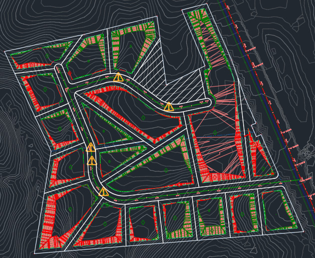
Figure 10.1 – Final grading object and grading surface for our Residential Subdivision
Technical requirements
The exercise files for this chapter are available at https://packt.link/UoiPn
Creating and managing assemblies
In this section, we’ll begin to learn all about assemblies and why they are considered to be the building blocks of all transportation-focused designs. Although a Residential Subdivision wouldn’t necessarily be considered a transportation design, our project requires us to design two roads, two intersections, one dead end, and one cul-de-sac. That said, assemblies in our design scenario are still going to be foundational modeled objects that will be utilized to execute an accurate roadway design.
Without further ado, let’s jump into our Assembly Creation and Management tools. We can access our basic Assembly tools by going back up to the Home ribbon, navigating to the Create Design panel, and selecting the down arrow next to Assembly.
As shown in Figure 10.2, we can see that we have two assembly tools available to us: Create Assembly and Add Assembly Offset:
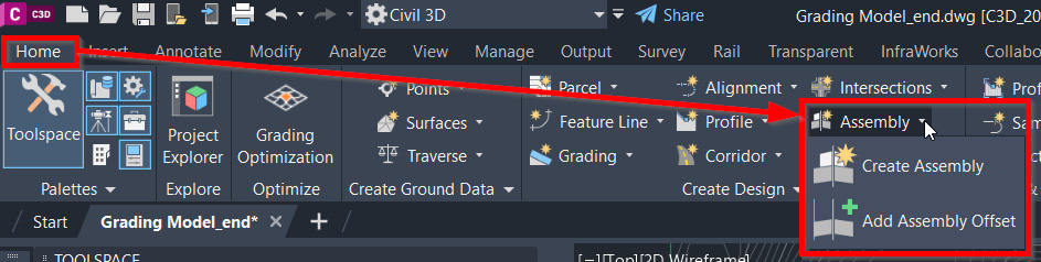
Figure 10.2 – Home | Create Design | Assembly
The Create Assembly tool allows us to do just that… create an assembly. The Add Assembly Offset tool is most commonly used when a service road needs to be designed that is offset from our main centerline alignment.
In our case, since we are only focusing on main roadways throughout our Residential Subdivision design layout, we will want to make the Create Assembly selection to start creating the assembly.
Once selected, we’ll be presented with the Create Assembly dialog box, at which point we’ll fill in the fields available as follows (also displayed in Figure 10.3), and then click on the OK button in the lower portion of the dialog box:
- Name: ASM – Subdivision Main Road – Access
- Description: Subdivision access road from York Hwy
- Assembly Type: Undivided Crowned Road
- Assembly style: Basic
- Code set style: All Codes
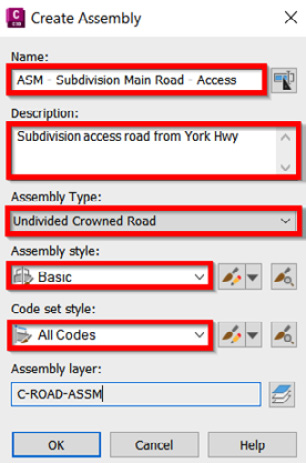
Figure 10.3 – The Create Assembly dialog box
After selecting the OK button, we must go back to the command line, where we’ll be asked to specify an Assembly Baseline Location. What I tend to do in these cases is specify my assembly baseline location near the profile views so that I can group horizontal and vertical components relatively close to each other.
That said, choose a location that you prefer (above, below, besides, and so on) next to your current profile views to place your assembly baseline. Once a location has been identified, Civil 3D will automatically zoom into that location so that only the assembly baseline is visible in your view, as shown in Figure 10.4:
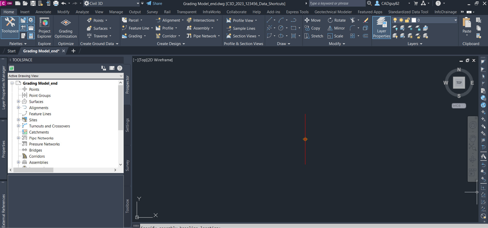
Figure 10.4 – Assembly baseline placed in the model space
Now, if we select our newly placed assembly baseline with our mouse, we’ll notice that the Assembly Contextual ribbon will appear, as shown in Figure 10.5. Running from left to right, we have the following panels with tools available to us:
- General Tools: This grants us access to various inquiry and display tools that will surface information and manipulate the appearance of our assembly objects
- Modify Subassembly: This grants us access to tools that will allow us to further manipulate the subassemblies that are attached to that particular assembly
- Modify Assembly: This grants us access to tools that will allow us to further manipulate our assembly objects
- Launch Pad: This grants us access to tools that will further progress and build out our assemblies and develop a corridor model within our current file:
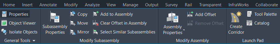
Figure 10.5 – The Assembly Contextual ribbon
Going into the Launch Pad panel, let’s go ahead and select the Tool Palette option. Once selected, the Subassembly Tool Palette area will appear on the screen, as shown in Figure 10.6.
This tool palette essentially calls up all the potential subassemblies, or building blocks, that we can use to add to our overall assembly, which will eventually be used to model our roadway corridor later in this chapter:
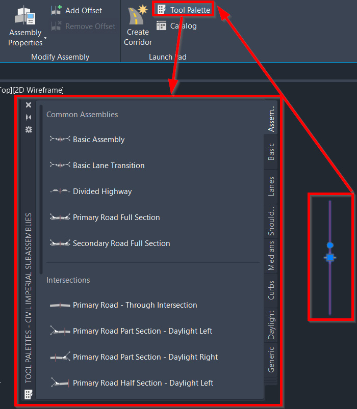
Figure 10.6 – Subassembly Tool Palette
Right off the bat, we will see that all subassemblies are displayed directly in the center section of the Subassembly Tool Palette area. Along the right-hand side of the Subassembly Tool Palette area, we will see a series of tabs that represent various groupings or categories of our subassemblies being displayed (refer to Figure 10.7).
Reading from top to bottom along the right-hand side, we have the following categories available to us:
- Assemblies – Imperial: Displays Civil 3D’s stock assembly templates that have been pre-developed to include multiple subassembly objects
- Basic: Displays basic individual subassembly objects that we can use to custom-build our assemblies
- Lanes: Displays individual lane-focused subassembly objects that we can use to custom-build our assemblies
- Shoulders: Displays individual shoulder-focused subassembly objects that we can use to custom-build our assemblies
- Medians: Displays individual median-focused subassembly objects that we can use to custom-build our assemblies
- Curbs: Displays individual curb-focused subassembly objects that we can use to custom-build our assemblies
- Daylight: Displays individual daylight-focused subassembly objects that we can use to custom-build our assemblies
- Generic: Displays individual generic subassembly objects that we can use to custom-build our assemblies
- Conditional: Displays individual conditional subassembly objects that will allow us to automate decision-making as we further custom-build our assemblies:

Figure 10.7 – Subassembly categories in the Tool Palette area
Furthermore, if we were to left-click in the bottom section of the tabbed area, we would be presented with a few more additional subassembly options that we can choose to be displayed in our Subassembly Tool Palette area (refer to Figure 10.8).
These additional subassembly tabs include the following:
- Trench Pipes: Displays Civil 3D’s stock Trench Subassembly groupings, which have been pre-developed to include multiple subassembly objects
- Retaining Walls: Displays Civil 3D’s stock Retaining Wall Subassembly groupings, which have been pre-developed to include multiple subassembly objects
- Rehab: Displays Civil 3D’s stock Rehab Subassembly groupings, which have been pre-developed to include multiple subassembly objects
- New Rehab: Displays Civil 3D’s stock New Rehab Subassembly groupings, which have been pre-developed to include multiple subassembly objects
- Bridge: Displays Civil 3D’s stock Bridge Subassembly groupings, which have been pre-developed to include multiple subassembly objects.
- Rail: Displays Civil 3D’s stock Rail Subassembly groupings, which have been pre-developed to include multiple subassembly objects:

Figure 10.8 – Subassembly categories in the Tool Palette area (expanded)
To design our first Residential Subdivision, we’re going to keep things fairly simple at this stage and leverage most of the basic and generic subassemblies available to us.
That said, let’s select our Basic tab to display all Basic Subassembly objects available to us. Running through the following steps, we can begin creating our assembly by adding a BasicLane subassembly to our overall assembly (refer to Figure 10.9 for visual steps):
- Select the BasicLane subassembly.
- Go to the Properties dialog box.
- Fill in the Parameters values we intend to apply to the BasicLane subassembly. In this instance, we’ll accept the default values, which are listed as follows:
- Version: R2019
- Side: Right
- Width: 12.00'
- Depth: 0.67'
- Slope: -2.00%
- We’ll see a note on the command line stating: Select marker point within assembly or [Insert Replace Detached]:. At this point, we can simply select our assembly baseline in our model space since we are ultimately looking to build our assembly at this point in our design:
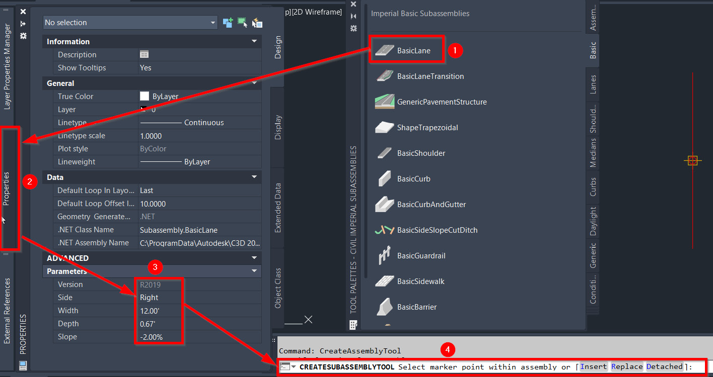
Figure 10.9 – Steps for adding a BasicLane subassembly
After selecting our assembly baseline, we will see our BasicLane subassembly attached to the centerline of our assembly. Before canceling out of the command, we can place our BasicLane subassembly as needed and change the values that are applied in the Parameters section of the Properties dialog as needed.
In our case, we will want to change the Side parameter from Right to Left and then select our assembly baseline again to place the left-hand side of our BasicLane subassembly, thereby completing a full road section. The new assembly should look similar to that shown in Figure 10.10:
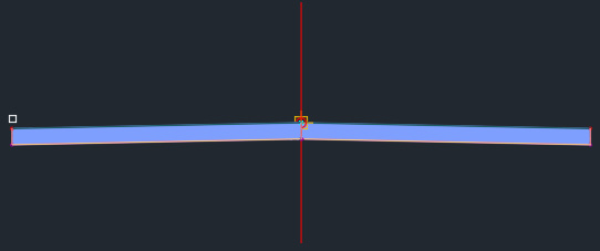
Figure 10.10 – BasicLane subassembly result
Next, we’ll want to add the BasicCurbAndGutter subassembly to the ends of our BasicLane subassembly. Running through the following steps, we can continue building our assembly by adding a BasicCurbAndGutter subassembly to our overall assembly (refer to Figure 10.11 for visual steps):
- Select the BasicCurbAndGutter subassembly.
- Go to the Properties dialog box.
- Fill in the parameters we intend to apply to our BasicCurbAndGutter subassembly. In this instance, we’ll accept the default values, which are listed as follows:
- Version: R2019
- Side: Left
- Insertion Point: Gutter Edge
- Gutter Width: 1.50
- Gutter Slope: -6.00%
- Curb Height: 0.75'
- Gutter Height: 0.50'
- We’ll see a note at the command line stating CREATESUBASSEMBLYTOOL: Select marker point within assembly or [Insert Replace Detached]:. At this point, we can simply select our top-left insertion node at the end of our BasicLane subassembly in our model space to attach the BasicCurbAndGutter subassembly at the edge:

Figure 10.11 – Steps for adding a BasicCurbAndGutter subassembly
Now that we’ve placed the BasicCurbAndGutter subassembly on the left-hand side, let’s cancel the command this time by hitting the Esc key on the keyboard. Although we still want to add the BasicCurbAndGutter subassembly to the right-hand side of our assembly, we’ll take a slightly different approach and become more familiar with the Subassembly Contextual ribbon.
Follow these steps to add the BasicCurbAndGutter subassembly to the right-hand side of our assembly:
- Select our newly placed BasicCurbAndGutter subassembly on the left-hand side of our assembly.
- Go to the Subassembly Contextual ribbon and select the Mirror tool in the Modify Subassembly panel.
- Select the top-right insertion node at the end of our BasicLane subassembly in our model space to attach the BasicCurbAndGutter subassembly at the edge:
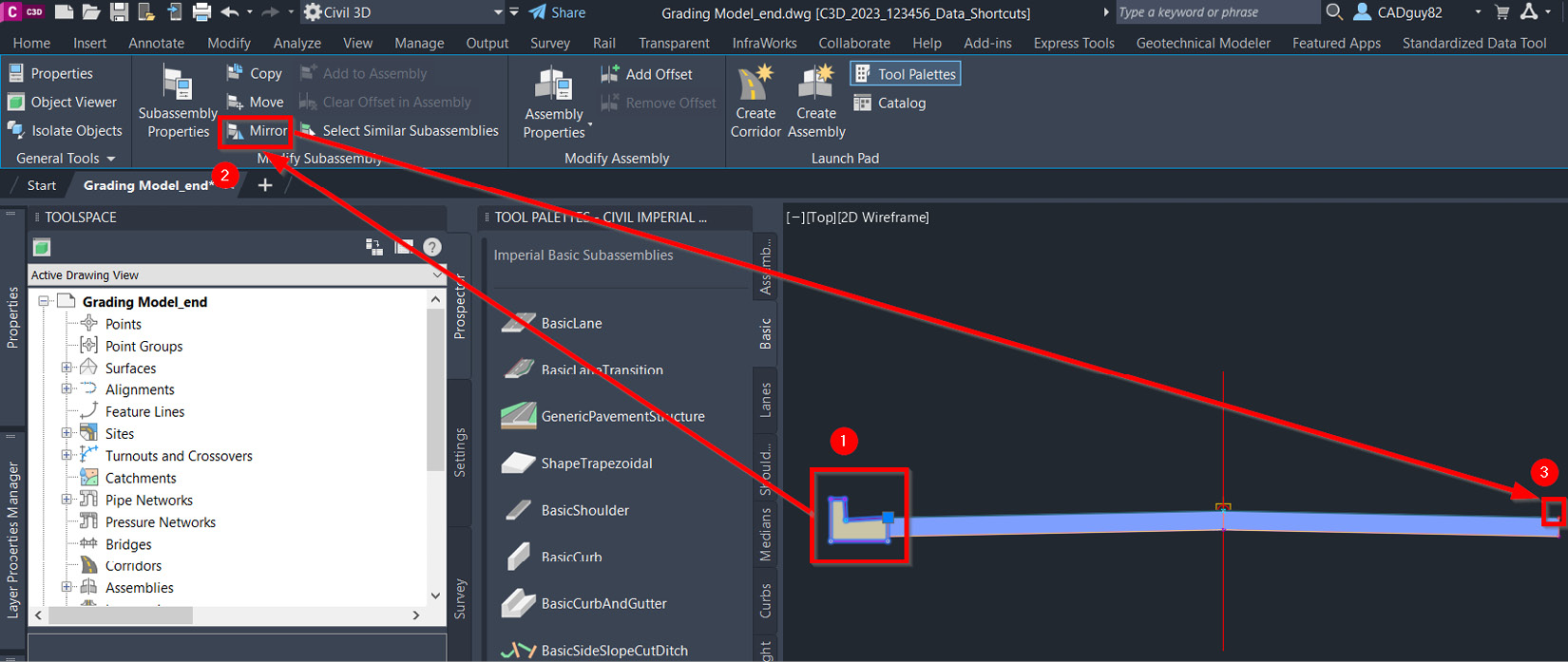
Figure 10.12 – Steps for mirroring a BasicCurbAndGutter subassembly
Although we can certainly continue building out our ASM – Subdivision Main Road – Access assembly by adding additional subassembly objects, we’re going to temporarily put that on hold as we’ll be looking at new ways to continue building our ASM – Subdivision Main Road – Access assembly later in this chapter.
Before jumping into the corridor creation process, we’ll want to make one more assembly that will be used for our dead-end and cul-de-sac portions of the corridor. Since both instances will require parameters to be input that extend beyond our alignment geometry, we’ll want to create an assembly that can run along a construction line representing our edge of pavement along our dead-end and cul-de-sac designs.
Instead of going back to the Home ribbon and running through the assembly creation process from scratch again, let’s go ahead and start with the ASM – Subdivision Main Road – Access assembly we just created and make the necessary modifications for our dead-end and cul-de-sac designs.
That said, let’s select the ASM – Subdivision Main Road – Access assembly baseline and use the AutoCAD COPY command (type COPY in the command line) and place the new assembly to the right, giving us two identical assemblies.
Let’s focus our attention on the newly created assembly to the right and select all subassemblies and use the AutoCAD ERASE command (type ERASE in the command line) to remove all subassemblies attached to our new assembly.
Next, select our assembly baseline again, right-click with our mouse, and select the Assembly Properties option to pull up the Assembly Properties dialog box. Once the Assembly Properties dialog box has appeared on the screen, name it ASM - Subdivision Main Road - Cul-De-Sac and set Description to Subdivision Cul-De-Sac Assembly. Then, select the OK button toward the bottom of the dialog box (refer to Figure 10.13 for the workflow):

Figure 10.13 – Steps for modifying the Name and Description fields of our new assembly
To build our ASM – Subdivision Main Road – Cul-De-Sac assembly, we must add subassemblies to further build it out:
- Select the BasicCurbAndGutter subassembly displayed on the right-hand side of our ASM – Subdivision Main Road – Access assembly.
- Go to the Subassembly Contextual ribbon.
- Navigate to the Modify Subassembly panel.
- Select the Copy tool.
- Select the baseline for our new ASM – Subdivision Main Road – Cul-De-Sac assembly.
- Hit the Esc key twice on your keyboard to cancel the command and deselect all.
Next, we want to add a slightly different type of Pavement section that will allow us to target the centerline of our roadway alignments. The reason we are using this approach is to make sure that we can maintain the elevations we have already established in our Design Profiles.
If we were to apply the BasicLane subassembly, we would essentially end up with varying elevations that may be in conflict with what we are proposing. If any vertical adjustments are made later to our Design Profiles, we can be confident that the corridor models will automate dynamically with them as well.
Follow these steps to add a new subassembly that will target horizontal and vertical geometry to maintain the parameters set in our design (this workflow is shown in Figure 10.14):
- In the Tool Palette area, select the BasicLaneTransition subassembly.
- Activate the Properties dialog box.
- Fill in the Parameters section as follows:
- Version: R2019
- Side: Left
- Insertion Point: Edge of Travel Way
- Crown Point on Inside: No
- Default Width: 12.00'
- Depth: 0.67'
- Default Slope: 2.00%
- Transition: Change offset and elevation
- Select the top-left corner node of the BasicCurbAndGutter subassembly to insert and attach it to BasicLaneTransition:

Figure 10.14 – Steps for attaching the BasicLaneTransition subassembly
Now that we have created our ASM – Subdivision Main Road – Access and ASM – Subdivision Main Road – Cul-De-Sac assemblies, let’s learn how we can utilize them to create our corridor models.
Creating and modifying corridors
With our ASM - Subdivision Main Road - Access and ASM - Subdivision Main Road - Cul-De-Sac assemblies created, albeit not fully built out, let’s learn how to create, manage, and manipulate our corridor models. So, let’s create our first corridor model in our Residential Subdivision design.
Select the ASM - Subdivision Main Road - Access assembly baseline to activate the Assembly Contextual ribbon. Then, go to the Launch Pad panel and select the Create Corridor tool.
Once selected, we’ll be presented with the Create Corridor dialog box, at which point we can fill in the fields as follows (also displayed in Figure 10.15), and then click on the OK button in the lower portion of the dialog box:
- Name: COR – Subdivision Main Road - Access
- Description: Subdivision access road from York Hwy
- Corridor style: Basic
- Baseline type: Alignment and profile
- Alignment: ALG – Subdivision Main Road – Access
- Profile: PRF – Subdivision Main Road – Access
- Assembly: ASM – Subdivision Main Road – Access
- Target Surface: <none>
- Set baseline and region parameters: Uncheck the box:

Figure 10.15 – The Create Corridor dialog box
After selecting the OK button in the Create Corridor dialog box, Civil 3D will run through the process of generating our new COR - Subdivision Main Road - Access corridor model along our ALG – Subdivision Main Road – Access alignment, with our Residential Subdivision design looking similar to that shown in Figure 10.16:
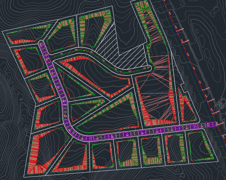
Figure 10.16 – Residential Subdivision for the first corridor model
Next, we’ll want to run through the same steps to call up the Create Corridor dialog box again, but this time, we’ll want to create our corridor along the ALG – Subdivision Side Road – Cul-De-Sac alignment. Once we’ve done that, we’ll want to fill out the fields in the Create Corridor dialog box as follows (also displayed in Figure 10.17):
- Name: COR – Subdivision Side Road – Cul-De-Sac
- Description: Subdivision Cul-De-Sac intersecting with Main Road
- Corridor style: Basic
- Baseline type: Alignment and profile
- Alignment: ALG – Subdivision Side Road – Cul-De-Sac
- Profile: PRF – Subdivision Side Road – Cul-De-Sac
- Assembly: ASM – Subdivision Main Road – Access
- Target Surface: <none>
- Set baseline and region parameters: Uncheck the box:
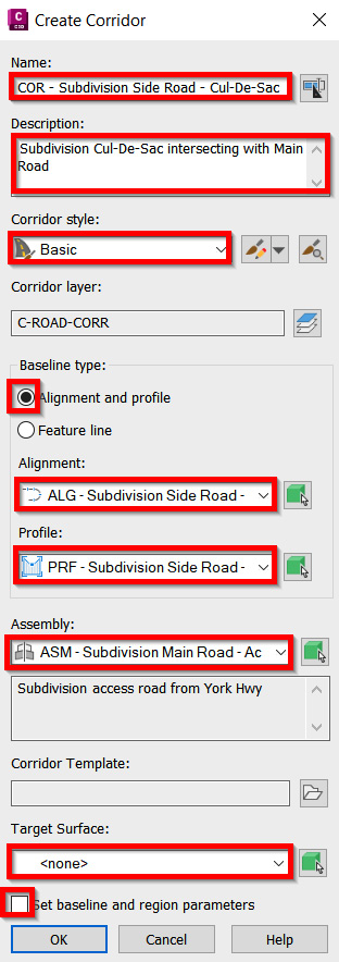
Figure 10.17 – The Create Corridor dialog box
After selecting the OK button in the Create Corridor dialog box, Civil 3D will run through the process of generating the COR – Subdivision Side Road – Cul-De-Sac corridor model, with the updated Residential Subdivision design looking similar to that shown in Figure 10.18:
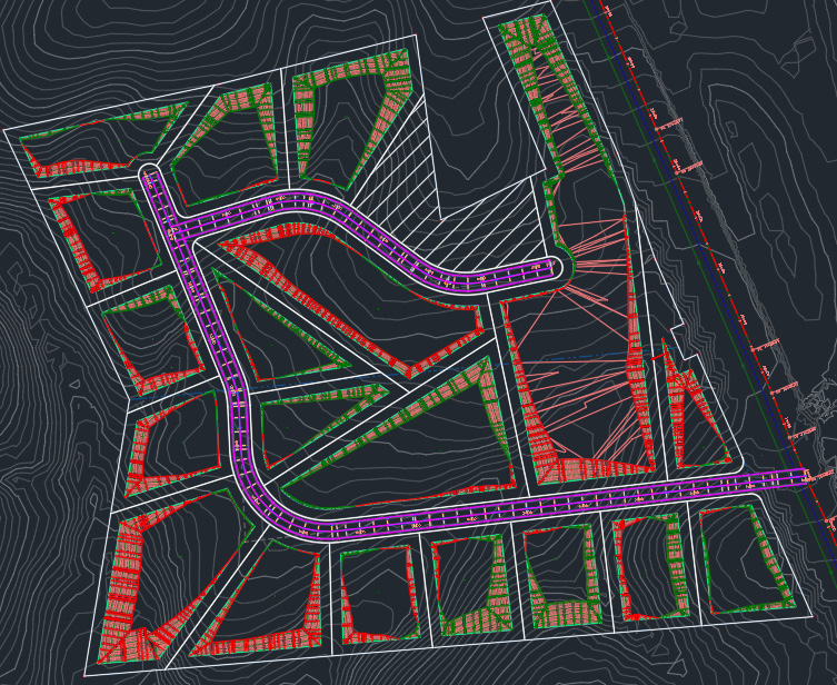
Figure 10.18 – Residential Subdivision for the second corridor model
As shown in our updated Residential Subdivision design, we have a couple of locations in one of the corridor models that will require some manipulation and updating. The following locations must be updated (also numbered and circled in Figure 10.19):
- At the entrance of our Residential Subdivision design where our ALG – Subdivision Main Road – Access alignment intersects with our ALG – Existing York Hwy – FromSurveyPoints alignment, we’ll want to move the starting point of our COR – Subdivision Main Road – Access corridor model to make room for our intersection design.
- At the end of our ALG – Subdivision Main Road – Access alignment, we’ll want to move the end point of our COR – Subdivision Main Road – Access corridor model to make room for our cul-de-sac design.
- At the end of our ALG – Subdivision Side Road – Cul-De-Sac alignment, we’ll want to move the end point of our COR – Subdivision Side Road – Cul-De-Sac corridor model to make room for our cul-de-sac design.
- Where our ALG - Subdivision Main Road – Access alignment intersects with our ALG - Subdivision Side Road - Cul-De-Sac alignment, we’ll want to make two adjustments. The first one will be to split our COR – Subdivision Main Road – Access corridor model and remove the section that intersects with our ALG – Subdivision Side Road – Cul-De-Sac alignment. The second will be to move the starting point of our COR – Subdivision Side Road – Cul-De-Sac corridor model. Both of these edits will essentially make room for our intersection design:

Figure 10.19 – Residential Subdivision for the second corridor model
To make edits 1-3 and part of 4, we can simply select our corresponding corridor models, zoom into the beginning and end locations, select the appropriate grip with our mouse, and slide our corridor start and end points at approximately 50', with the updated appearance looking similar to that shown in Figure 10.20:
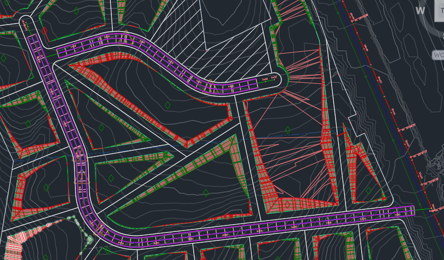
Figure 10.20 – Residential Subdivision after performing edits 1-3
To split our COR – Subdivision Main Road – Access corridor model and remove the section that intersects with our ALG – Subdivision Side Road – Cul-De-Sac alignment, we’ll want to use the Corridor Contextual ribbon.
So, let’s go ahead and select our COR – Subdivision Main Road – Access corridor model, then go to the Modify Region panel in the Corridor Contextual ribbon. We’ll want to select the Split Region tool twice to create a section within our COR – Subdivision Main Road – Access corridor model that can be removed (refer to Figure 10.21 for split locations):
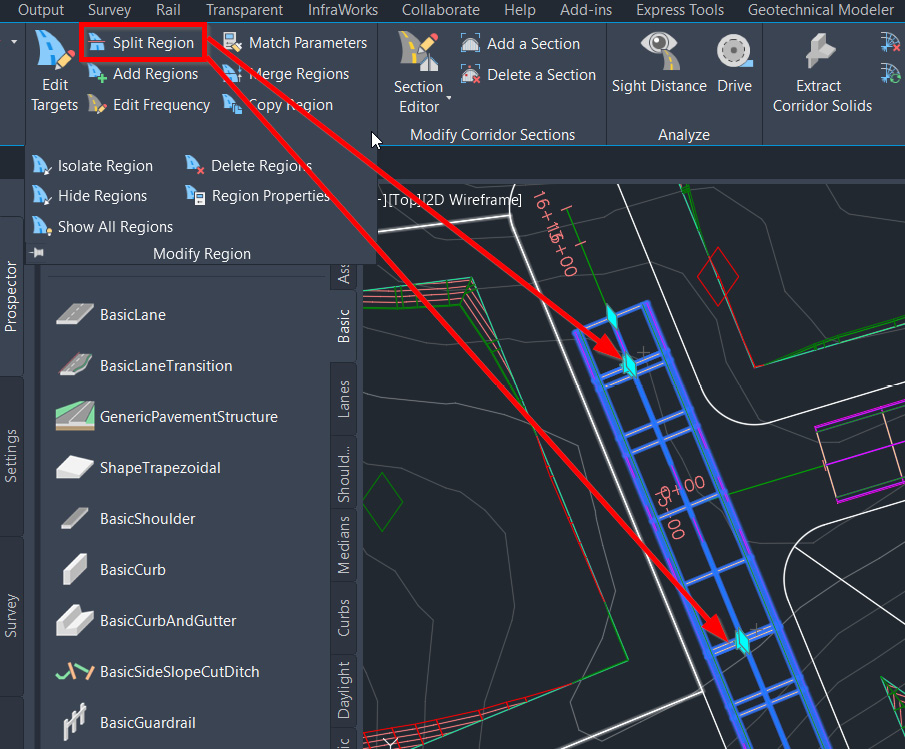
Figure 10.21 – Split Region for the corridor model
Next, we’ll use the Delete Regions tool to remove the region that intersects with our ALG – Subdivision Side Road – Cul-De-Sac alignment (refer to Figure 10.22).
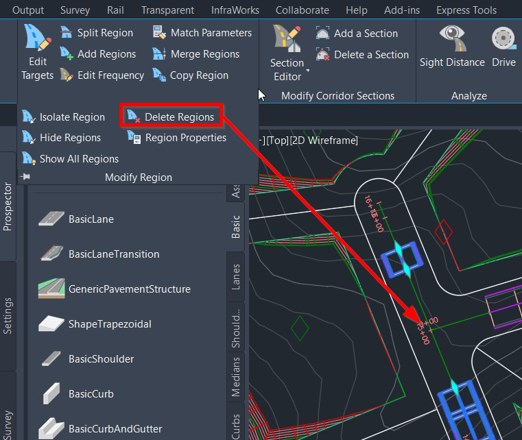
Figure 10.22 – Delete Regions for the corridor model
Now that we’ve made room for our intersection and cul-de-sac models along our alignments, let’s go ahead and explore these tools a bit more to further our Roadway designs.
Creating and modifying intersections and cul-de-sacs
You may have noticed by now that our cul-de-sac situation needs to be updated a bit as it relates to our linework. As with most designs, there tends to be a bit of scope creep, and very rarely are we able to complete a design in our first pass.
In this instance, we had originally laid out our parcels with the assumption that the roadway following our ALG – Subdivision Side Road – Cul-De-Sac alignment would be a dead end. Our client has now asked that we make this an official cul-de-sac, which will require us to adjust our parcel layout slightly to accommodate the extended turnaround capacity.
That said, utilizing a combination of our AutoCAD tools and our Civil 3D tools, we’ll need to make a few adjustments to our Residential Subdivision design. To update our Right-of-Way and parcels in the vicinity of our cul-de-sac, we’ll want to start by opening up our Site Plan Reference.dwg file located within Practical Autodesk Civil 3D 2024Chapter 10Reference.
Once opened, let’s zoom into the location of the cul-de-sac at the end of our ALG – Subdivision Side Road – Cul-De-Sac alignment, draw a circle with a 38’ radius while the center of our circle is snapped to the end of our ALG – Subdivision Side Road – Cul-De-Sac alignment, then use the Trim command to trim out the circle portion that lies within the right-of-way, as shown in Figure 10.23:
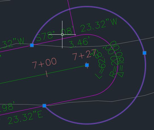
Figure 10.23 – Arc representing a new parcel boundary
Next, we’ll go ahead and select our right-of-way parcel to activate our Parcel Contextual ribbon. Within the Parcel Contextual ribbon, we’ll want to click on the Edit Geometry icon in the Modify panel, then select the Edit Curve tool within the Edit Geometry panel, as shown in Figure 10.24:
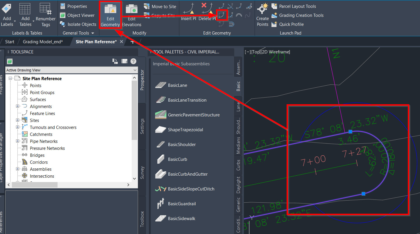
Figure 10.24 – Edit Curve parameters
Once the Edit Curve tool has been selected, at the command line, we’ll be prompted to select the feature line curve to edit or delete, at which point we’ll select the curve at the end of our right-of-way.
Once selected, the Edit Feature Line Curve dialog box will appear. Let’s go ahead and change the Radius value to 38.00'. After changing the value and clicking the Apply button, we’ll see the anticipated parcel layout automatically display (refer to Figure 10.25):
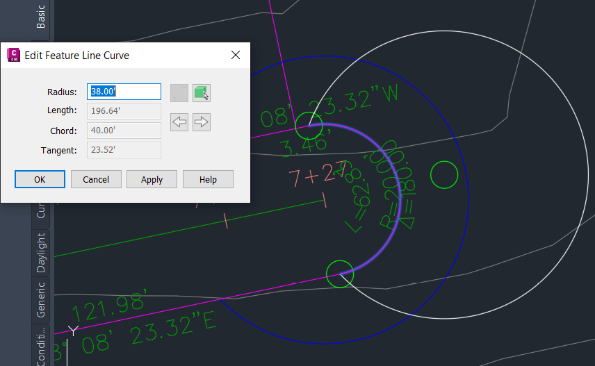
Figure 10.25 – Updated parcel curve layout
Then, click OK to accept and make a few more modifications. If we select the right-of-way parcel one more time, we’ll want to move the grips to the end points of the temporary arc we created earlier (refer to Figure 10.26 for the workflow):
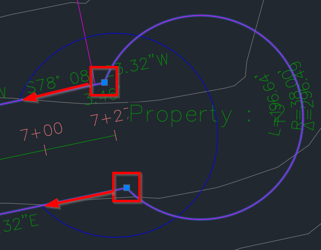
Figure 10.26 – Updated parcel layout
Once updated, go ahead and save your changes, and close out and reopen the Grading Model.dwg file located within Practical Autodesk Civil 3D 2024Chapter 10Model.
In the Grading Model.dwg file, do the following to create our edge-of-lane linework:
- Zoom into the same location as before.
- Draw a circle with a radius of 30 ft.
- Offset the ALG – Subdivision Side Road – Cul-De-Sac alignment by 12' on either side (temporarily).
- Use the offset lines to trim our newly created circle.
- Fillet our offset lines and arc with a radius of 25'.
- Use the Polyline Edit or Join command to create one continuous polyline of all three arcs.
- Erase the offset lines. We should be left with the edge-of-lane being displayed in our cul-de-sac, similar to that shown in Figure 10.27:
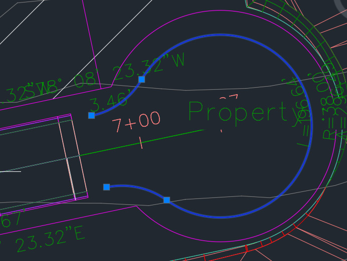
Figure 10.27 – Edge-of-lane arc in our cul-de-sac
The final steps we’ll need to take before creating our cul-de-sac corridor model will be to convert our newly created arc into a feature line so that our cul-de-sac corridor model can use as a baseline while reading both horizontal and vertical geometry.
That said, follow these steps to accomplish this:
- Select Create Feature Line from the Object option under Home | Create Design | Feature Line.
- Select the arc depicting the edge-of-lane we just created and hit the Enter key on your keyboard.
- When the Create Feature Lines dialog appears, we’ll want to create a New Site in our first (top) field and name it SIT – Proposed – Cul-De-Sac. Then, set the Description property to Cul-De-Sac Feature Lines and select OK.
- Change Feature Line Style to Corridor Edge of Travel Way.
- Check the boxes for Erase Existing Entities and Assign Elevations and click the OK button.
- In the Assign Elevations dialog box, we’ll want to select the From Surface option to read our elevations from our SRF – Existing Grade – FromSurveyPoints Surface model and uncheck the box next to Insert intermediate grade break points so that we are left with one continuous slope through the entire length of our newly converted feature line.
Note
We will update elevation assignments later in this chapter.
With our feature line created, we can now use the same steps we went through in the previous section to create a corridor. When the Create Corridor command has been initiated, we’ll want to fill in the corresponding fields in our Create Corridor dialog box:
- Name: COR – Subdivision Cul-De-Sac
- Description: Subdivision Cul-De-Sac
- Corridor style: Basic
- Baseline type: Feature Line
- Site: Cul-De-Sac
- Feature Line: FL – Subdivision Cul-De-Sac
We will likely need to use the Select option under Drawing. Once this icon is selected, we’ll be prompted to physically select the feature line in our model space.
Once selected, we’ll be prompted to input a name for that particular feature line.
Let’s go ahead and name it FL – Subdivision Cul-De-Sac and click OK:
- Assembly: ASM – Subdivision Main Road – Cul-De-Sac
- Target Surface: <none>
- Set Region and Baseline Parameters: Check the box
Since we checked the box this time for Set Region and Baseline Parameters, we’ll see the Baseline and Region Parameters dialog box appear. The main reason for pulling this dialog box up at this stage is to identify the target for the BasicLaneTransition subassembly so that it will target the horizontal and vertical geometry associated with our ALG – Subdivision Side Road – Cul-De-Sac alignment and our PRF – Subdivision Side Road – Cul-De-Sac profile, respectively.
With our Baseline and Region Parameters dialog box in view, let’s go ahead and select the Set all Targets button (shown in Figure 10.28):

Figure 10.28 – The Baseline and Region Parameters dialog box
Then, select the Transition and ALG – Subdivision Side Road – Cul-De-Sac alignments (shown in Figure 10.29):
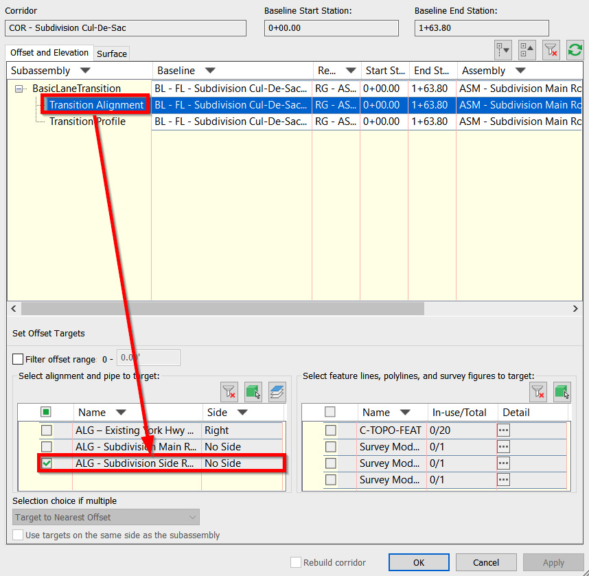
Figure 10.29 – Target Mapping | Transition Alignment
Then, select the Transition and PRF – Subdivision Side Road – Cul-De-Sac profiles (shown in Figure 10.30):
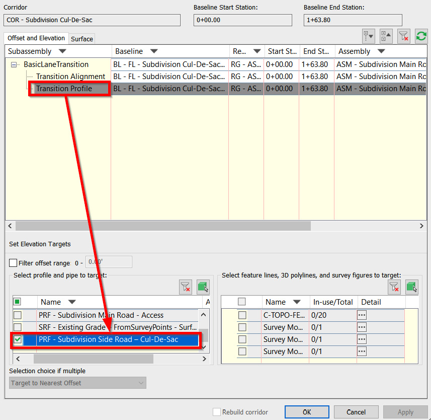
Figure 10.30 – Target Mapping | Transition Profile
Finally, select the OK button on both dialog boxes and let Civil 3D create the new cul-de-sac corridor model.
With our cul-de-sac created, let’s move on to our intersection, where our ALG – Subdivision Main Road – Access and ALG – Subdivision Side Road – Cul-De-Sac alignments meet.
Let’s follow these steps to familiarize ourselves with Civil 3D’s Intersection Wizard:
- Going back to Home | Create Design, we’ll select the down arrow next to Intersections and select the Create Intersection tool.
- In the command line, we’ll notice that we are asked to select an Intersection Point. Once prompted, we’ll want to zoom into our intersection and snap to the intersection point (using AutoCAD’s OSNAPS) to identify the intersection point.
- Civil 3D’s Create Intersection dialog box will appear, starting with the General tab. We’ll want to fill out the fields as follows in our General tab (also displayed in Figure 10.31) and select the Next button at the bottom of the Create Intersection dialog box:
- Intersection Name: INT – Subdivision Side Road – Cul-De-Sac
- Description: Intersection of Subdivision Main Road and Side Road Alignments
- Intersection marker style: Intersection Marker
- Intersection label style: Basic
- Intersection corridor type: All Crowns Maintained:

Figure 10.31 – Create Intersection | General
- Next, we must fill in the fields in the Geometry Details tab as follows (also displayed in Figure 10.32) and select the Next button at the bottom of the Create Intersection dialog box:
- Create or specify offset alignments: Check the box
- Create curb return alignments: Check the box
- Create offset and curb return profiles: Check the box:

Figure 10.32 – Create Intersection | Geometry Details
- Next, let’s fill in the fields in the Corridor Regions tab as follows (also displayed in Figure 10.33) and select the Create Intersection button at the bottom of the Create Intersection dialog box:
- Create corridors in the intersection area: Check the box
- Create a new corridor: Check the box
- Corridor Region Section Type: Accept all default Assemblies being applied:

Figure 10.33 – Create Intersection | Corridor Regions
- After selecting the Create Intersection button in the Create Intersection dialog box, our intersection corridor model will be created, similar to that shown in Figure 10.34:

Figure 10.34 – Create Intersection | Corridor Regions
We’ll notice a few things going on in our current model:
- The first, most obvious, one is that in this view alone (refer to Figure 10.34), a few additional subassemblies have been applied to our intersection corridor model.
- Second, if we navigate to the Toolspace | Prospector tab and expand our corridors and intersections, we’ll notice that we now have a Corridor - (1) model. Although not very intuitive, this is associated with our newly created intersection.
Let’s go ahead and give this a name and description that is more closely aligned with its purpose in our Residential Subdivision design. If we right-click on the Corridor – (1) object and select the Properties option, we’ll be presented with the Corridor Properties dialog box.
If we activate the Information tab in the Corridor Properties dialog box, we’ll want to set Name to COR - Intersection of Subdivision Main Road and Cul-De-Sac and Description to Intersection of Subdivision Main Road and Side Road Alignments, and then select the OK button in the lower portion of the Corridor Properties dialog box.
- The third item that has changed in our Grading Model.dwg file is that we now have a series of additional subassemblies that have been created and are available to us. If you recall back to the Create Intersection process, in the Corridor Regions tab, we accepted the defaults while listing out multiple assemblies to apply, at which point Civil 3D automatically generated and placed these assemblies into our model space (refer to Figure 10.35):

Figure 10.35 – Assemblies created during the intersection design process
As you can see with the default assemblies, there are quite a few differences between the subassemblies used to generate our COR – Intersection of Subdivision Main Road and Cul-De-Sac corridor model with those applied to all other corridor models in our file.
Using similar tactics to modify our assemblies in the previous section, we can use the Assembly Contextual ribbon, navigate to the Modify Subassembly panel, and use a combination of the Copy, Move, and Mirror tools available alongside the AutoCAD Erase command to rebuild our subassemblies. Ultimately, we’ll want to replace the lanes applied in the default Intersection Assemblies area with a BasicLane, and then add our Daylight Subassemblies to our Main Road Assemblies.
It’s also recommended to move the assemblies that were used to create our COR – Intersection of Subdivision Main Road and Cul-De-Sac corridor model so that they’re closer to our other assemblies to ensure they are all grouped. After moving and applying all edits, our grouped assemblies should look similar to that shown in Figure 10.36:
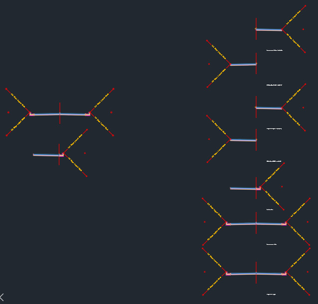
Figure 10.36 – Grouped assemblies after updating
Now that we’ve updated all our assemblies, we’ll want to go back to the Toolspace | Prospector tab, scroll down to the corridor objects listed, right-click on Corridors, and select the Rebuild All option, as shown in Figure 10.37, allowing us to update all the models in our file in one clean swoop:
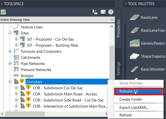
Figure 10.37 – Rebuild All
The final pieces to the corridor puzzle we’ll want to perform are related to the targeting and frequency being applied to all of our corridors. At this point, our corridor models are essentially floating in the model space without any real tieback to our existing surface.
Now that we’ve added daylight subassemblies to all of our assemblies, we’ll want to make sure we specify that we want to target our daylight lines to our SRF – Existing Grade – FromSurveyPoints surface model. Concerning the Frequency settings, we’ll want to apply a tighter frequency to all of the corridor models in our file.
By applying a tighter frequency interval, we are ultimately making our roadway designs much more accurate and smoother, thus providing us with a better product in the end.
That said, let’s go to the Modify ribbon toward the top of our Civil 3D session and select the Corridor tool within the Design panel, as shown in Figure 10.38:

Figure 10.38 – Modify | Design
Once the Corridor tool has been selected, our ribbon and panels will switch to the Corridor Contextual ribbon. If we shift our focus to the Modify Region panel, we’ll be able to activate our Edit Targets tool, as well as our Edit Frequency tool, as shown in Figure 10.39:
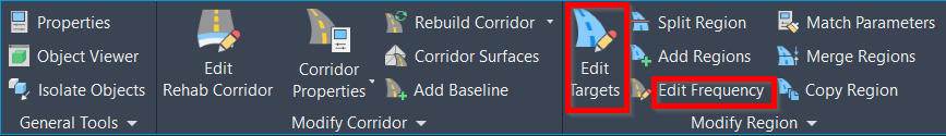
Figure 10.39 – Corridor Contextual | Modify Region
If we go ahead and select the Edit Targets tool, we’ll be prompted to select the corridor that we’d like to update in the command line. After selecting one of our corridor models, we’ll then be asked to specify the region within the selected corridor that we’d like to update, at which point we’ll type (or select) All, bringing up the Target Mapping dialog box.
Now, let’s use the Select a surface for all surface targets option and select our SRF – Existing Grade – FromSurveyPoints surface model, and then click the OK button at the bottom of our Target Mapping dialog box (refer to Figure 10.40).
Perform these steps to apply surface targeting to all additional corridor models in our current file:

Figure 10.40 – The Target Mapping dialog box
Next, we’ll want to update the frequency settings for all of our corridor models. Once the Edit Frequency tool has been selected, we’ll be prompted to select the corridor that we’d like to update. After selecting any of our corridor models, we’ll be prompted to select the region that we’d like to update.
Unlike the Targeting option, we will need to place our mouse within the corridor extents (corridor extents will be highlighted) and left-click to accept the identified section.
Once the section has been accepted, the Frequency to Apply Assemblies dialog box will appear, at which point we’ll want to update the values to 5’ for now to create a much smoother and more accurate corridor model (refer to Figure 10.41).
Note
Changing our Frequency values to smaller intervals, although providing a much smoother and more accurate Corridor model, will also result in increased file size, longer Corridor rebuilding times, and longer opening and saving times.
That said, at earlier stages of design, it is recommended that we use the default Frequency values. As we approach our final design or Issued for Construction phase, we’ll want to apply smaller intervals to ensure that our design models are as accurate as we can get.

Figure 10.41 – The Frequency to Apply Assemblies dialog box
Now that we have created a fairly tight design for our corridor models, let’s learn how to generate surfaces from our corridor models and integrate them into our overall Residential Subdivision design.
Creating a surface from corridors
With our corridor models created, we can now learn how to properly apply horizontal and vertical values associated with them to generate a dynamically linked surface model. As with all other modeled objects we’ve created, it’s important to keep these links intact to minimize rework later on down the road and avoid the major risk of missing or overlooking a required update along the way.
If we go back to Modify | Design and select the Corridor tool again, we’ll bring up the Corridor Contextual ribbon once more. There, we’ll want to go to the Modify Corridor panel and select the Corridor Surfaces tool (refer to Figure 10.42):

Figure 10.42 – Corridor Contextual | Modify Corridor | Corridor Surfaces
Once selected, we’ll be prompted to select the corridor that we’d like to update. After selecting any of our corridor models, the Corridor Surfaces dialog box will appear. In the Surfaces tab, do the following to generate the surface model that will be dynamically linked to our corridor model (also shown in Figure 10.43):
- Select the Surfaces tab.
- Select the Create a Corridor Surface icon.
- Set Data type input to Links.
- Set Specify code to Top.
- Select the Add Surface Item icon.
- Set Surface Style to Contours 1’ and 5’ (Design).
- Check the Add as Breakline box (this setting will provide additional definition and accuracy for our surface model):

Figure 10.43 – Steps for creating a corridor surface
Next, we’ll switch over to the Boundaries tab within the Corridor Surfaces dialog box, right-click on our newly created corridor surface model and select the Corridor extents as outer boundary option (refer to Figure 10.44), and then select the OK button at the bottom of the Corridor Surfaces dialog box.
By applying Corridor extents as outer boundary to our corridor surface model, we are ensuring that Civil 3D will not attempt to interpolate outside of the corridor limits and that our corridor surface boundary is terminating where it is meeting our SRF – Existing Grade – FromSurveyPoints surface model:

Figure 10.44 – Corridor Surfaces | Boundaries
After closing out of the Corridor Surfaces dialog box, a surface model will be displayed in our model space.
Using these same steps, let’s go ahead and generate corridor surfaces for all four corridors. Once all four corridor surfaces have been created, we’ll want to combine them into one comprehensive surface model:
- Going back to the Toolspace | Prospector tab, we’ll want to expand the surfaces to view all surface models in our current file.
- After running through the process of creating a surface, as we learned in Chapter 6, Surfaces - The First Foundational Component to Designs within Civil 3D, name this comprehensive surface model SRF – Proposed Grade – Corridors with Description as Combined Corridor Surface Models.
- Next, we’ll want to expand SRF – Proposed Grade – Corridors Surface, then expand Definitions. If we right-click on Edits and select the Paste Surface option, we’ll be presented with the Select Surface to Paste dialog box.
- Here, we’ll want to double-click on our surfaces in the following order (also shown in Figure 10.45):
- COR – Subdivision Main Road – Access Surface
- COR – Subdivision Side Road – Cul-De-Sac Surface
- COR – Intersection of Subdivision Main Road and Cul-De-Sac Surface
- COR – Subdivision Cul-De-Sac Surface:
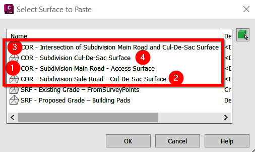
Figure 10.45 – The Select Surface to Paste dialog box
Once all the corridor surfaces have been pasted, resulting in one comprehensive SRF – Proposed Grade – Corridors surface model, we’ll want to add to our Data Shortcuts project by performing the steps outlined in previous chapters using the Create Data Shortcuts option. The final output should look similar to that shown in Figure 10.46:
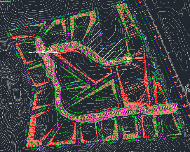
Figure 10.46 – Final Residential Subdivision appearance
Summary
As we worked through this chapter, we made significant progress toward shoring up our roadway design throughout our Residential Subdivision design. We learned why assemblies and subassemblies are considered to be the building blocks of all transportation-focused designs.
We also learned how to create corridor models, intersections, and cul-de-sacs using our alignments, profiles, assemblies, and subassemblies. We even sprinkled in some adjustments that needed to be made to our parcel layout due to design change requests, and how to create one combined surface model that reflects all corridor surface models created in our file.
In the next chapter, we’ll take a few steps further beyond our typical Roadway Modeling tool belt and pull out our Advanced Roadway Modeling tool belt before progressing with our Utility modeling tool belt to finish up our Residential Subdivision design. By understanding what Utility Modeling tools are available to us in Civil 3D, we’ll be able to design a Storm Drainage network, Sanitary Sewer network, and Domestic Water network that will not only support our new Residential Subdivision but also tie into the existing networks along York Highway.