
12
Sheet Metal Design – Comprehensive Methodologies to Create Sheet Metal Products
Autodesk Inventor has a specific design environment for the creation, editing, and detailing of sheet metal CAD components. Sheet metal parts are parts that are fabricated from a sheet of material with a uniform thickness. These sheet metal parts are subject to certain design constraints and sheet metal-specific manufacturing processes. Although specific to sheet metal parts, any parts that you create of uniform thickness in a standard part file can also use the sheet metal functionalities.
Within Inventor, sheet metal parts can be displayed as a folded model or a flat pattern. With the sheet metal functionality, you can work on sheet metal parts in both a folded and an unfolded state. Inventor enables you as the designer to set important sheet metal defaults/rules based on the equipment you have available for manufacture, for example, bend radii, K factors, material thickness, and corner seam type.
The ability to fold and refold the material, generate bend tables, and so on means the digital model created can greatly improve and enhance the physical manufacturing process.
A typical sheet metal design workflow is as follows.
The creation of a sheet metal part starts with a sheet metal template. The sheet metal template file is configured and stores the specific set of sheet metal rules. Adjusting and changing the rules enables the selection of different materials, thicknesses, and more.
Initially, a base feature is created. A sheet metal base feature is often a face of a shape. Additional sheet metal-specific features are then added. The sheet metal component does not have to start exclusively with a single flat face; alternatively, this could be a contour roll.
If a part is created with consistent thickness, with the standard modeling method, it can be converted into a sheet metal part in Inventor. This is also the case for non-native imported CAD models.
The typical sheet metal workflow is as follows:
- Define sheet metal rules.
- Start the creation of a base feature/face.
- Apply secondary sheet metal features (holes, cuts, flanges, and hems).
- Unfold and refold the model as appropriate.
- Document the design in the drawing area of Inventor.
- Export the folded and flat pattern design in the desired format, such as .dxf for manufacture.
Figure 12.1 shows an example of a sheet metal part created in Inventor and highlights some of the key sheet metal-specific features that can be created:

Figure 12.1: Sheet metal part highlighting specific sheet metal features
The sheet metal tools, upon selecting a sheet metal template in the part modeling environment, show the breadth of features that can be created:

Figure 12.2: Sheet metal environment active
In this chapter, you will learn about the following:
- Setting up and configuring your sheet metal template
- Creating a sheet metal part with faces, flanges, bends, hems, and cuts
- Applying advanced sheet metal base features – Contour Flange, Lofted Flange, and Contour Roll
- Converting a solid into a sheet metal part and performing a rip
- Creating and applying a custom sheet metal punch
- Designing sheet metal parts in assemblies and .dxf output
- Detailing sheet metal parts in the drawing environment
Technical requirements
To complete this chapter, you will need access to the practice files in the Chapter 12 folder within the Inventor Cookbook 2023 folder. It is important that you have a good understanding of the essential Inventor modeling techniques. An appreciation and understanding of sheet metal fabrication techniques is not essential but recommended.
Setting up and configuring your sheet metal template
This recipe will focus on the initial setup of a sheet metal template, prior to the creation of a sheet metal part. This process does not have to be carried out each time a sheet metal part is required. Once a template has been configured, it can be saved and used again, applying the settings and constraints to the next design. Multiple sheet metal templates can be configured, and in most cases will be required based on the materials and fabrication equipment available to the engineer.
Getting ready
To begin this recipe, you will not need any practice files.
How to do it…
We will start by creating a blank new sheet metal document, and then we will configure the desired sheet metal rules and settings within this. The last step will be to save this as an accessible template for future use:
- From the Inventor Home screen, select New followed by New. Select Templates | en-Us, then select Metric. Select Sheet Metal (mm).ipt and then Create.
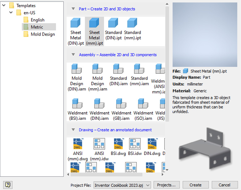
Figure 12.3: Sheet metal default template
- A new sheet metal part file will open. Navigate to the far right of the ribbon, in the Sheet Metal tab, and select Sheet Metal Defaults.

Figure 12.4: Sheet Metal Defaults
This is where we can configure the template sheet metal rules.
- Select Edit Sheet Metal Rule as shown in Figure 12.5.
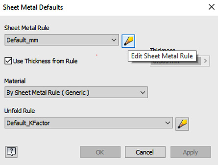
Figure 12.5: Edit Sheet Metal Rule
- Select Default, then select New… to create a new local style.
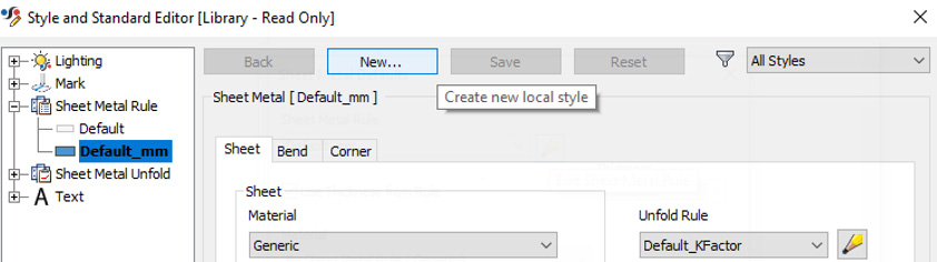
Figure 12.6: New local style
- Name your new local style Sheet Metal TEST and select OK.
- The settings applied in reality will be dependent on the material and fabrication equipment. The following settings are not reflective of a real-world manufacturing facility. Under Material, select Stainless Steel. For Thickness, change this to a value from .500 mm to 1 mm. Leave the default value of Report Bending Angle (A).
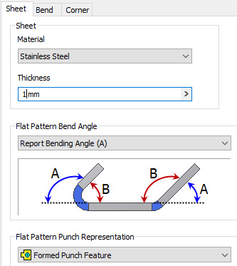
Figure 12.7: Material and Thickness settings
- Select the Bend tab in the Style and Standard Editor dialog box.
- Change Relief Shape to Round, and leave all other settings as the default. Select the Corner tab from Style and Standard Editor.

Figure 12.8: Bend relief options
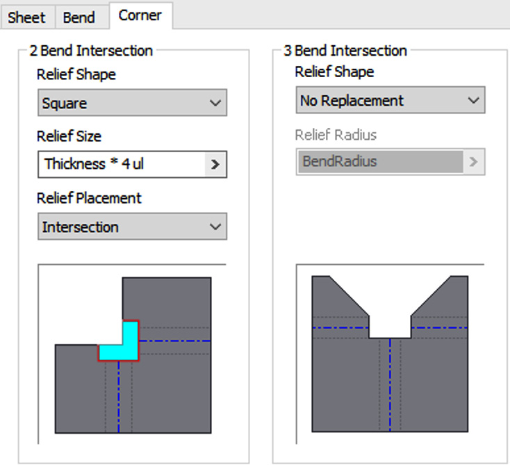
Figure 12.9: Corner settings to apply
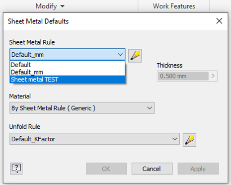
Figure 12.10: Sheet Metal TEST template
- Select File | Save As | Save Copy As Template.
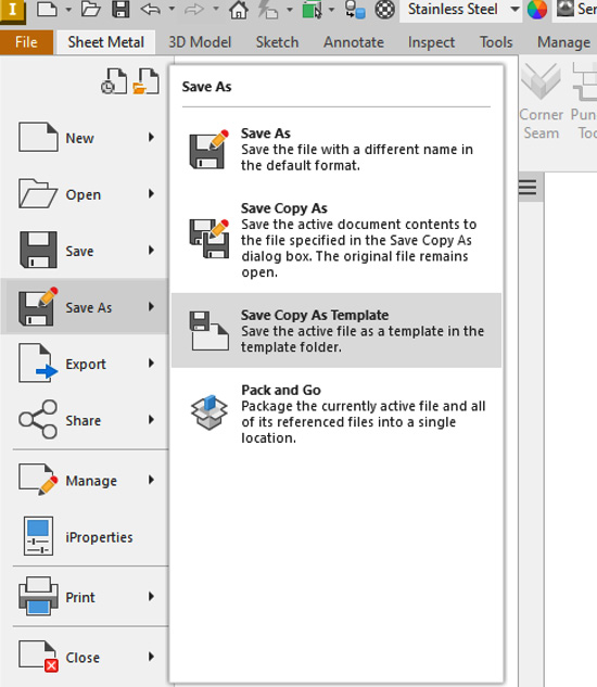
Figure 12.11: Save Copy As Template
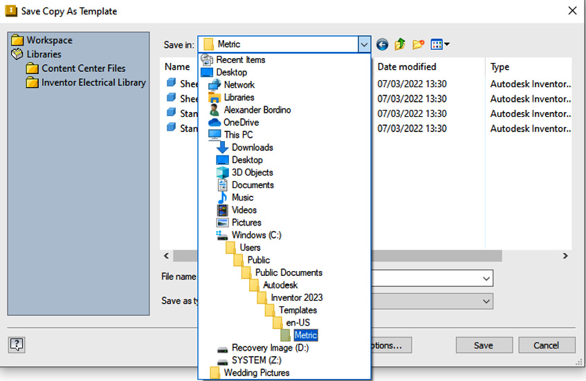
Figure 12.12: File path to browse to save a template
- Select Save.
- Now select File | New. The new Sheet Metal TEST.ipt template is available for selection with all the settings we previously applied in this recipe active.
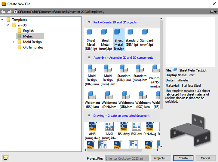
Figure 12.13: Sheet Metal TEST.ipt template available
By using the sheet metal defaults, you have defined and created a custom sheet metal template file, ready for future sheet metal component creation. This means that future parts created with this sheet metal template will follow the same sheet metal rules.
Creating a sheet metal part with faces, flanges, bends, hems, and cuts
You will create a basic sheet metal part using key feature commands such as Face, Flange, Bend, and Hem to create the final part. You will also learn how to unfold and refold a model.
Getting ready
You will not need any practice files for this recipe.
How to do it…
The first steps will involve creating a new sheet metal part and defining the base feature. From there, we will then start to use the sheet metal functionality to create the additional required features:
- From the Inventor Home screen, select New followed by Templates | en-US | Metric. Then, select Sheet metal (mm).ipt and then Create.
- Select Start 2D Sketch, then select the XZ plane. Select Rectangle | Two Point Center Rectangle, and then create the base sketch, as defined in Figure 12.14:

Figure 12.14: Initial sketch to create a 100 mm x 25 mm rectangle
Then, select Finish Sketch.
- Select Face from the Sheet metal tab.
- The profile is already selected to apply the default sheet metal and default thickness from the sheet metal rule in the template. Select OK.
- Now, we will change the default thickness of the material. Select Sheet Metal Defaults and uncheck Use Thickness from Rule. Define a new thickness of .650 mm. Select OK.

Figure 12.15: Sheet Metal Defaults to adjust the thickness
The face previously created in steps 3 and 4 will update in thickness from .500 mm to .650 mm.
- Create a new sketch on the top face of the sheet metal part. Create the sketch as per Figure 12.16. These sketch lines will form the basis of a fold operation.
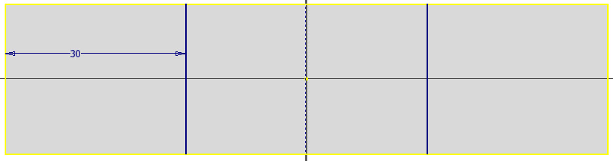
Figure 12.16: New sketch to define
- From the sheet metal tools, select Fold. Select the sketch line shown in Figure 12.17 as the reference. Use Flip Controls so that the direction of the bend is as in Figure 12.17. Leave Fold Angle at 90 degrees. Select OK to complete. A fold is applied to the sheet metal part.
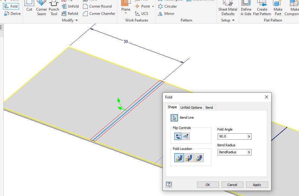
Figure 12.17: Fold to apply to a face
- We will now replicate the fold on the other side of the part. Select Share the Sketch from Sketch2. Select Fold and then select the opposite sketch line to the one in step 7. Apply a 90-degree fold in the opposite direction. The result is as per Figure 12.18:
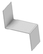
Figure 12.18: Second fold operation applied
- As with all other features in Inventor, you can edit the sheet metal features using the Model Browser. Right-click on Fold2 from the Model Browser and select Edit Feature. Adjust Bend Angle to 60 degrees.
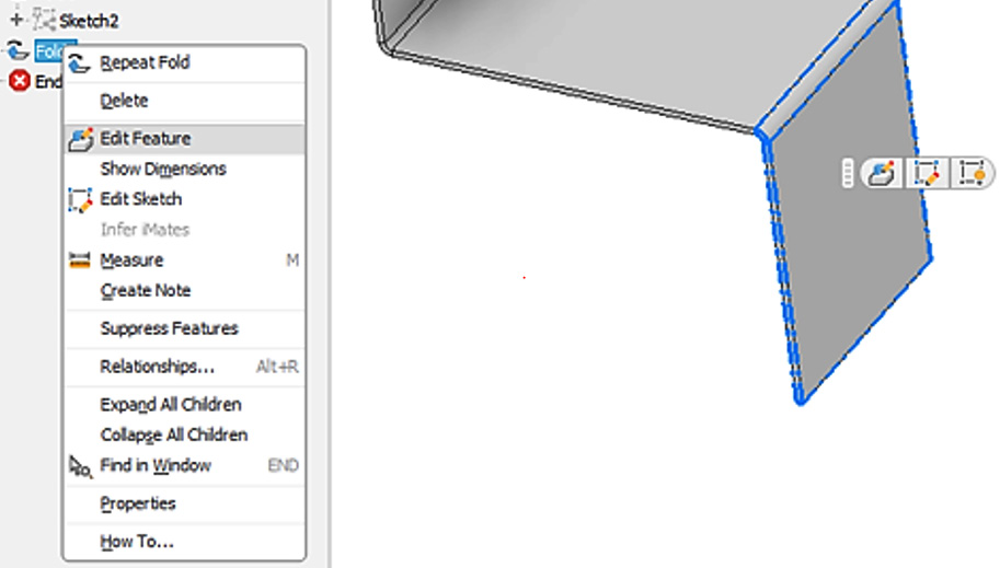
Figure 12.19: Edit Feature of a sheet metal feature
- Select the Flange command. By selecting existing edges on a sheet metal part, you can specify and apply various Flange features. Multiple edges can be selected at once if the type of flange is to be the same. Select the four edges shown in Figure 12.20:

Figure 12.20: Edges of the flange selected
- Change Height Extents to 10 mm. Bend Rules, Bend Position, and Angle can also all be adjusted. By default, Inventor will use values previously defined in the sheet metal rules in the template file. Select Apply to apply these flanges.
- Select the edge shown in Figure 12.21, then change Height Extents to 20 mm and Angle to 70 degrees. Select OK.
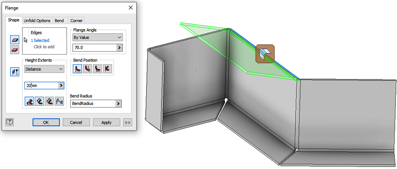
Figure 12.21: Second flange to apply
- In the sheet metal create tools, in the ribbon, select Hem. This allows you to apply Hem features to sheet metal edges. Select the edge shown in Figure 12.22:
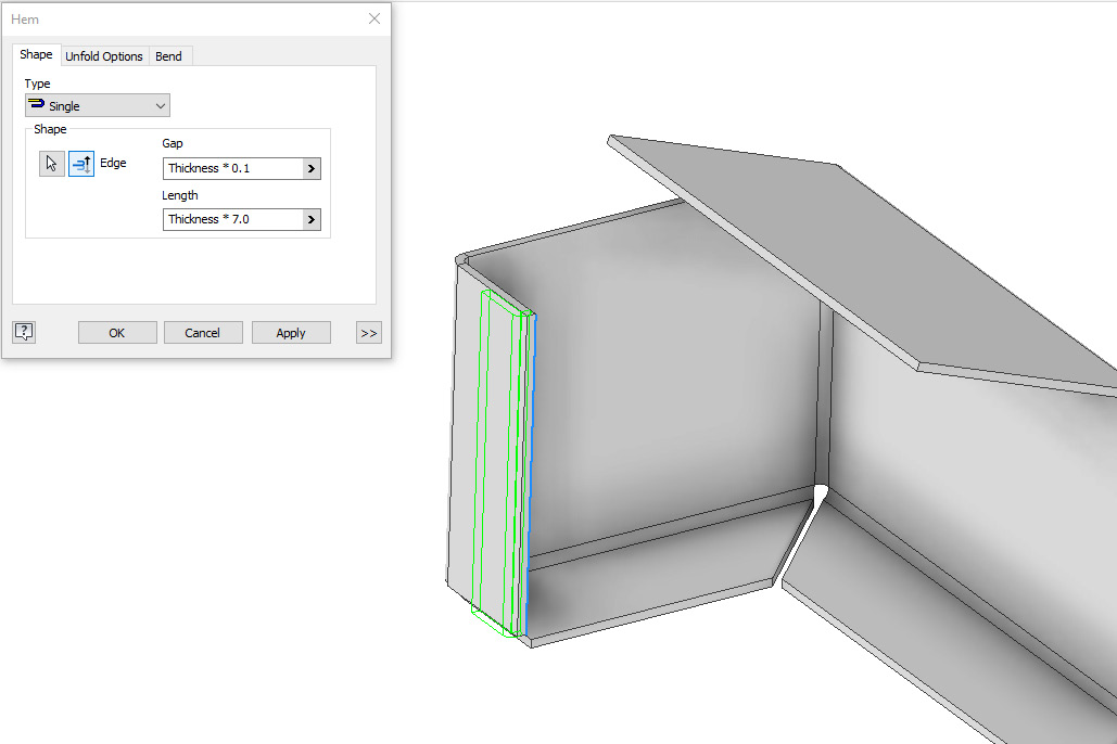
Figure 12.22: Hem to apply
- Change Type to Single. Adjust Thickness to Thickness * 0.1 and Length to Thickness * 7.0. Select Apply to complete.
- Select the edge shown in Figure 12.23. Change Type to Teardrop. Select the >> button. Change Width Type Extents to Width | Centered. Change Width to 20 mm.

Figure 12.23: Second hem to apply
- We will now perform a Cut operation on one of the faces. Select the face shown in Figure 12.24 and then Start 2D Sketch. Then, proceed to create the sketch as defined in Figure 12.25.

Figure 12.24: Face to start the 2D sketch
- By pressing F7 once, the sketch plane is selected, which will allow you to slice the graphics to gain a better view of the face.

Figure 12.25: Sketch to create for the cut
- Select Finish Sketch. Select Cut, then select the sketch slotted profiles and select OK to complete.
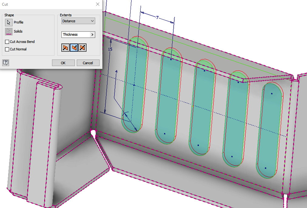
Figure 12.26: Cut operation to perform on sketched profiles
- Now, we will unfold and refold the model. During the Unfold operation, Inventor will scan the part and ensure that no intersections are present. This could possibly indicate flaws that would mean aspects of the part would be unmanufacturable. Select Unfold, then select the Stationary Reference as the Face, as shown in Figure 12.27. Select Add All Bends and then select OK.
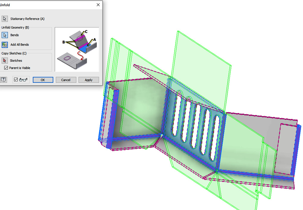
Figure 12.27: Unfold operation
A warning displays that informs you that there is an intersection of material in the part. Select Accept to proceed. The flat pattern is shown, as in Figure 12.27. The circled area in Figure 12.28 is the possible intersection and problem area:
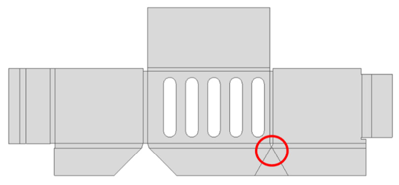
Figure 12.28: Part unfolded
A design change is required here prior to manufacture.
- Select Ctrl + Z to cancel the Unfold operation. Edit Flange1.
- Use Ctrl to deselect the edge shown in Figure 12.29 and select OK to complete the edit to Flange1:

Figure 12.29: Edge to deselect from Flange1
- Select Unfold. Select the same face for the stationary reference as before in step 18. Select All Bends to be included and select OK. The Unfold operation is performed without any warnings as the problem area has been rectified.
- Select Refold, then select the same stationary reference as step 22. Select All Bends and then OK. The part is folded back.
You have successfully created a simple sheet metal part using a face base feature, flanges, bends, hems, and cuts. You have also used Unfold/Refold to identify problems prior to manufacture, and then addressed the issue.
Applying advanced sheet metal base features – Contour Flange, Lofted Flange, and Contour Roll
The face feature is not the only base feature available. Contour Flange, Lofted Flange, and Contour Roll can all be used as base features. In this recipe, you will learn how each is created at a basic level. All these operations require an open sketch to begin with.
Getting ready
To begin this recipe, you will need to navigate to Inventor Cookbook 2023 | Chapter 12. Then, open Contour Flange & Roll.ipt.
With Contour Flange & Roll.ipt open, you will see that there is already an open sketch created. This sketch will provide the structure for the Contour Flange feature. The profile will be extruded, and the default sheet metal thickness value will be added.
All bend radii are added to the sketch.
Contour Flange can be used as a base feature or secondary feature. It is often used to create a rolled feature or multiple flanges on a sheet metal part.
How to do it…
The sketch profile we require for Contour Flange has already been created, so we will head straight into the sheet metal feature tools:
- Select Contour Flange. The sketch profile is automatically picked up in the preview.
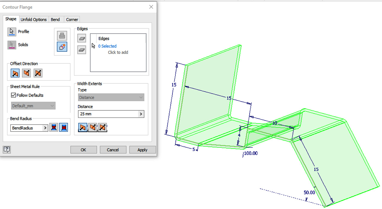
Figure 12.30: Contour Flange selected and a preview displayed
- Change Distance from 25 mm to 15 mm. The preview will update.
- Select OK to complete.
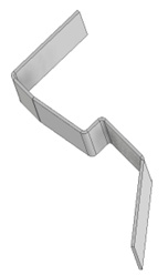
Figure 12.31: A contour flange is created from the sketch
Using Contour Flange, complex sheet metal forms can be made in a single operation, rather than multiple flanges and bends. Additional sheet metal features can now be added if required to the model.
- Delete the contour flange feature but maintain the original sketch by deselecting the checkbox in the warning.
- We will now perform a contour roll on the same sketch profile. This requires additional sketch geometry to act as an axis of revolution. Right-click Sketch1 in the Model Browser and select Edit Sketch. Create the sketch lines as shown in Figure 12.32:
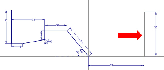
Figure 12.32: Sketch line added to act as an axis of revolution
- Select Finish Sketch. Select Contour Roll.
- Select the original sketch profile as the profile. Then, select the new sketch line created in step 5 as the axis. The Contour Roll preview is created as per Figure 12.33:

Figure 12.33: Contour Roll preview
- Now, we will adjust the contour roll parameters before completing the operation. Change Rolled Angle to 100 degrees. Then, select OK to complete.
The contour roll is completed.
- Close Contour Flange & Roll.ipt.
- Now, we will create a lofted flange using the sheet metal function. From the Chapter 12 folder, open Lofted Flange.ipt.
- The part contains two separate sketches of different profiles set on separate planes 50 mm from each other. We will create lofted flange between the two and create a sheet metal part that transitions from one profile to another.
- Select Lofted Flange.
- For Profile 1, pick the circle sketch in the Graphics Window. Select the ellipse for Profile 2. The preview of the lofted flange will generate the following:

Figure 12.34: Lofted flange preview
- We can now adjust the various options for the lofted flange. Output is the main factor – we can either switch from Press Brake as displayed or to a Die Formed solution, under Output. Leave this as Press Brake. This is shown in the Output section of Lofted Flange, as in Figure 12.34.
- With Press Brake, Facet Control can be adjusted to either Chord Tolerance, Facet Angle, or Facet Distance. Select Chord Tolerance for this solution. Leave Tolerance as 0.5 mm and select OK to complete.
You have created several other base feature options for sheet metal parts in the form of Contour Flange, Lofted Flange, and Contour Roll.
Converting a solid into a sheet metal part and performing a rip
In this recipe, you will take an existing solid body part in Inventor, convert it into a sheet metal part, and then perform a Rip operation on the part.
Getting ready
To begin this recipe, you will need to navigate to Inventor Cookbook 2023 | Chapter 12 and open Rip.ipt.
The part has been created via a lofted extrusion, followed by a Shell operation. This has created a solid body part. First, we need to convert this into a sheet metal component. As this has a uniform thickness of 2 mm, this is achievable.
How to do it…
We will start the process of converting the part into a sheet metal part, then we will define the reference points to perform the rip:
- In the 3D Model tab, navigate to the far right of the ribbon. Select Convert to Sheet Metal. Select one of the angled faces as the base feature. Select OK for Sheet Metal Rules. The part is converted into a sheet metal part.
- Right-click on the top angled face and select Start 2D Sketch. Select Project Geometry and select the face to project the edges of the part to the sketch. Select Finish Sketch.
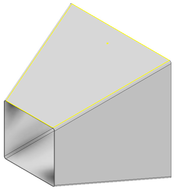
Figure 12.35: Projected sketch of top face
- Select Rip from the Sheet Metal tab in the ribbon.
- Keep Type as Single Point and select the face previously sketched on in step 2 as the rip face. Then, select the midpoint of the edge of the shape, as shown in Figure 12.36. A preview of the rip will be shown:
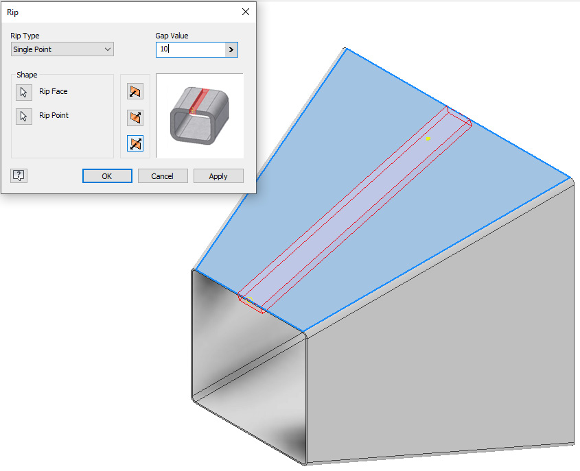
Figure 12.36: Rip face and rip point to select
- Overwrite GapSize to 10 mm. Then, select OK.
You have now converted a solid model into a sheet metal part and then performed a Rip operation. To ensure that converted solid models behave as expected when converted into a sheet metal, you must ensure the following:
- There is a consistent thickness to the model
- The sheet metal thickness parameter value matches that of the sheet metal rules
- There is some form of gap in the model and it is not a continuous face
- There is a rounded fillet on the outside edge
If these rules are not adhered to, converted sheet metal parts will not be able to be unfolded or have additional sheet metal features added.
Creating and applying a custom sheet metal punch
In this recipe, you will create a custom sheet metal punch file. You will then use this punch file in another sheet metal part. The punch tool can either remove or deform a material, and once created, can be reused in other files. Punch tools are extracted in a similar way to a standard iFeature.
Getting ready
You will not require a practice file to start this recipe. Create a new Sheet metal (mm) .ipt file.
How to do it…
We will begin by creating a face and then detailing the punch:
- When creating punch tools, Inventor requires only one central point to locate this. Automatically, Inventor will project the origins and center points of sketch objects, which will make creating the punch difficult. For this reason, in your new Sheet metal (mm) .ipt file, select Tools | Application Options, then select the Sketch tab. Uncheck Autoproject part origin on sketch create. You can re-apply this setting after the punch has been created.
- Select Start 2D Sketch, and create a sketch on the XY plane, as Figure 12.37 shows:

Figure 12.37: Initial sketch to create
This will be a 50 x 50 mm square at 0,0,0, the origin, as origin projection is temporarily turned off.
- Select Face, and then select the sketch you created in step 2. Uncheck Sheet Metal Defaults for Thickness and change this from .500 mm to 1 mm. Select OK to complete.
- Create a new 2D sketch on the face, as shown in Figure 12.38. This will become the punch tool detail.
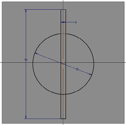
Figure 12.38: Sketch of punch tool to apply to the face
- Once you have drawn the sketch as detailed in Figure 12.38, select Point from the sketch tools and select the center of the circle. This will be the locating point for the punch tool.
- Select Cut, and then select the sketch previously created in step 4. Select the Distance and type Thickness. Select OK to complete.
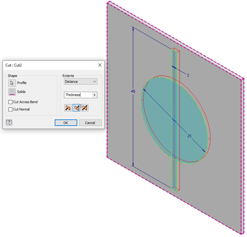
Figure 12.39: Cut applied to the sketch previously created
- In the Model Browser, right-click Sketch2 of the punch tool detail and select Share Sketch. This makes the sketch selectable when we export it as a punch file.
- The punch is now complete. Now, we will define and extract it as a punch file. Select the Manage tab, then navigate right to the Author commands and select Extract iFeature.
Figure 12.40: Extract iFeature
- Select Sheet Metal Punch iFeature for Type in the Extract iFeature dialog.
- Then, select Cut1 from the Model Browser to bring this into the Selected Features section of Extract iFeature.

Figure 12.41: Options detailed in steps 9 and 10 selected
- Under Simplified Representation, select the red cursor for sketch selection. Select the shared sketch, Sketch2, from the Model Browser.
- Under Specify Punch ID, type PunchTool01. Select Save.
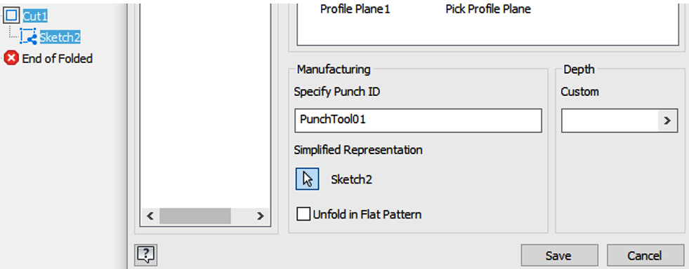
Figure 12.42: Punch ID specified and shared reference sketch selected
- Inventor will now prompt you to save the file under a folder called Catalog. Rename the file PunchTool01, which is the same as your punch ID. Then, select Save. Select Yes on the warning.
- The punch tool has now been successfully created and saved to an accessible library. Select Tools | Application Options, then select the Sketch tab. Click the checkbox for Autoproject part origin on sketch create. Save the Inventor file as PunchTool01 in Chapter 12.
- From the Chapter 12 folder, open Part to Punch.ipt.
- Select the Manage tab, then select Insert iFeature.
Figure 12.43: Insert iFeature
- Select PunchTool01 from the Catalog folder, then select Open.
- When prompted to pick a profile plane, select the large rectangular face of the part, as shown in Figure 12.44. This will place the part centrally on the origin of the face. Alternatively, sketch points could be added to place the punch tool.
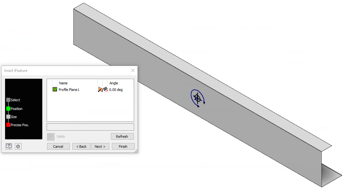
Figure 12.44: Punch tool location defined
- Select Next, then Next again, and then select Finish. PunchTool01 is applied to the part and the material is removed.
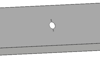
Figure 12.45: PunchTool01 applied
- In this instance, we require multiple features to be punched into this face. Rather than importing the iFeature again to create more punch holes, we can instead apply a feature pattern of the punch cut to create the desired outcome in a more efficient way. Using the Feature Pattern tool, create the pattern shown in Figure 12.46:
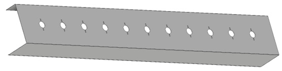
Figure 12.46: PunchTool01 feature pattern to create more punch holes
You have created a custom sheet metal punch tool as a sheet metal punch tool iFeature, saved this to an accessible library, and then used and applied it to a punch material on an existing sheet metal part.
Designing sheet metal parts in assemblies and .dxf output
In many instances, it can be advantageous to design the sheet metal part required within the context of an existing assembly. Within Inventor, you can use multiple modeling techniques to achieve this with standard parts, and this also extends to sheet metal parts.
In this recipe, we will design and place an additional component for a wall-mounted TV bracket. Once complete, we will then produce flat patterns and export the final design to a .dxf file for manufacture.
Getting ready
To begin this recipe, you will need to navigate to Inventor Cookbook 2023 | Chapter 12 and open TV Bracket Assembly.iam.
The assembly file contains an incomplete TV wall-mounted bracket, as shown here:
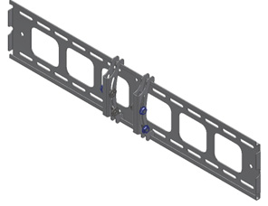
Figure 12.47: Incomplete TV wall-mounted bracket assembly – TV Bracket Assembly.iam
In this recipe, we will use sheet metal tools and standard modeling practices to create a new component in the context of the assembly. Once complete, we will generate a flat pattern of the component and export it as a .dxf file for manufacture.
How to do it…
We will begin by creating an in-place component of the additional bracket required. A face base feature will be defined, and then additional sheet metal features will be added. Once the part is complete, we will then duplicate and add another instance of this to the assembly:
- Select the Assemble tab, then select Create.
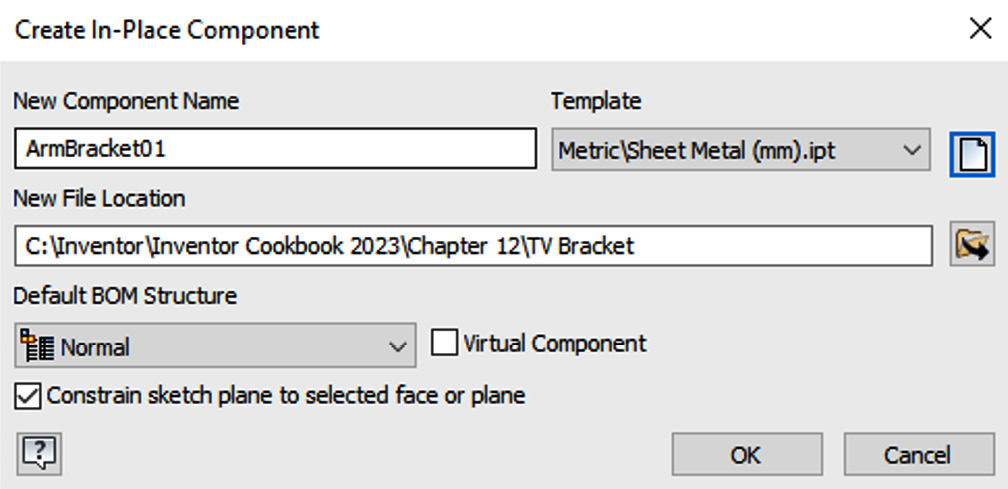
Figure 12.48: Component name, template, and file location
- In the Create In-Place Component window, we now need to define New Component Name, Template, and New File Location for the new part:
- For New Component Name, type ArmBracket01
- For Template, select the Browse command, select Metric, and then select Sheet Metal (mm).ipt
- Ensure New File Location is set to Inventor Cookbook 2023Chapter 12 TV Bracket
- Select OK to complete
- Select the face of the model highlighted in Figure 12.49 as the reference:

Figure 12.49: Face to select as a reference
- We are now creating an in-place component within the assembly. The sheet metal tools are now visible in the ribbon. Select Start 2D Sketch, then select the same face that is shown in Figure 12.49 as the plane to sketch from. You may have to reorientate the model at this point.
- In the new sketch, select Project Geometry and then select the two circles shown in Figure 12.50:
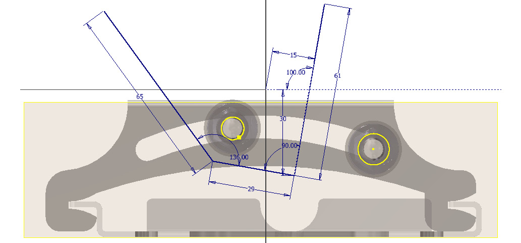
Figure 12.50: Existing geometry to project in the sketch
We will now define the first face of the sheet metal part.
- Using the Line | Construction Line and Dimension commands, generate and define the sketch lines of the first face, as shown in Figure 12.51:
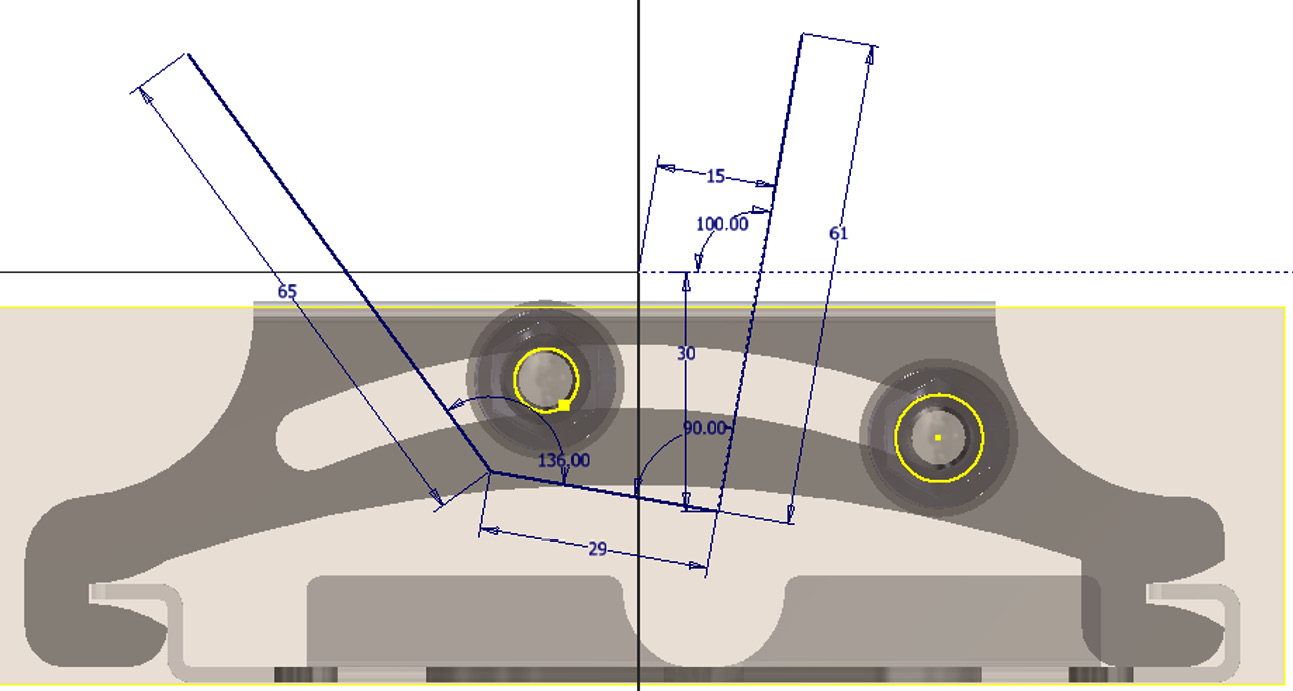
Figure 12.51: First sketch lines to generate
- In the same sketch, add the remaining sketch geometry, as shown in Figure 12.52. Ensure that the sketch is fully defined before proceeding. Then, select Finish Sketch. You can also access the completed version of this file if required, with the completed final sketch. Go to Inventor Cookbook 2023|Chapter 12|TV Bracket| and open TV Bracket Assem Complete.iam.

Figure 12.52: Remaining sketch geometry to apply
- Select Mirror. Select all geometry to mirror and then select the line highlighted as the mirror line in Figure 12.53. Select Apply to complete.

Figure 12.53: Mirror sketch to apply
- Select Line and draw the final line, as shown in Figure 12.54, to complete a closed profile for the face. Then, select Finish Sketch.
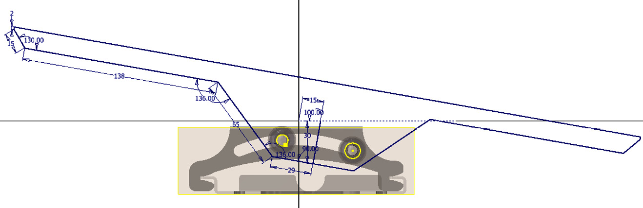
Figure 12.54: Final line to apply
- Select Sheet Metal Defaults, then uncheck Use Thickness from Rule and type a new value of 3 mm for Sheet Metal Thickness. Select Apply.
- Select Face, then select the sketch profile completed in step 9.
- During the preview, move the view so you can see the bolted connection from the side. Ensure that the plate meets the washer. Then, select OK.
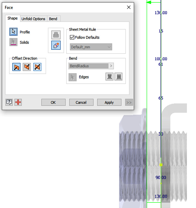
Figure 12.55: Face selected and 3 mm thickness applied
- Select Start 2D Sketch and create a sketch on the face of the solid generated, as shown in Figure 12.55. Sketch the geometry shown in Figure 12.56, which will form a sheet metal cut in the next step:
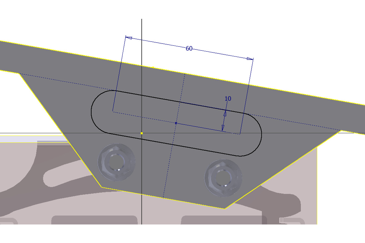
Figure 12.56: Slot geometry to sketch
- Select Finish Sketch. Then, select Cut.
- Select the sketch profile of the slot created in step 13. Ensure Cut Distance is set to Thickness and select OK.
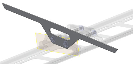
Figure 12.57: Cut performed
- Select Start 2D Sketch. Select the same face as before for the plane.
- Using Project Geometry, project the holes shown in Figure 12.58. Then, select Finish Sketch.

Figure 12.58: Holes to project in the sketch
- Select the Hole command from the Sheet Metal tab. Select the two center points projected previously as the Hole centers. Under Type, select Simple for Hole and None for Seat. Then, enter 10 mm for the diameter. Select OK to generate the two cut holes.
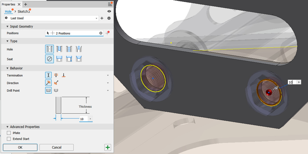
Figure 12.59: Hole command to generate two required holes
- Select the Flange command from the Sheet Metal tab. Select the edge shown in Figure 12.60. Change Flange Angle to -90 degrees and Distance to 11 mm. Select OK to apply the changes.
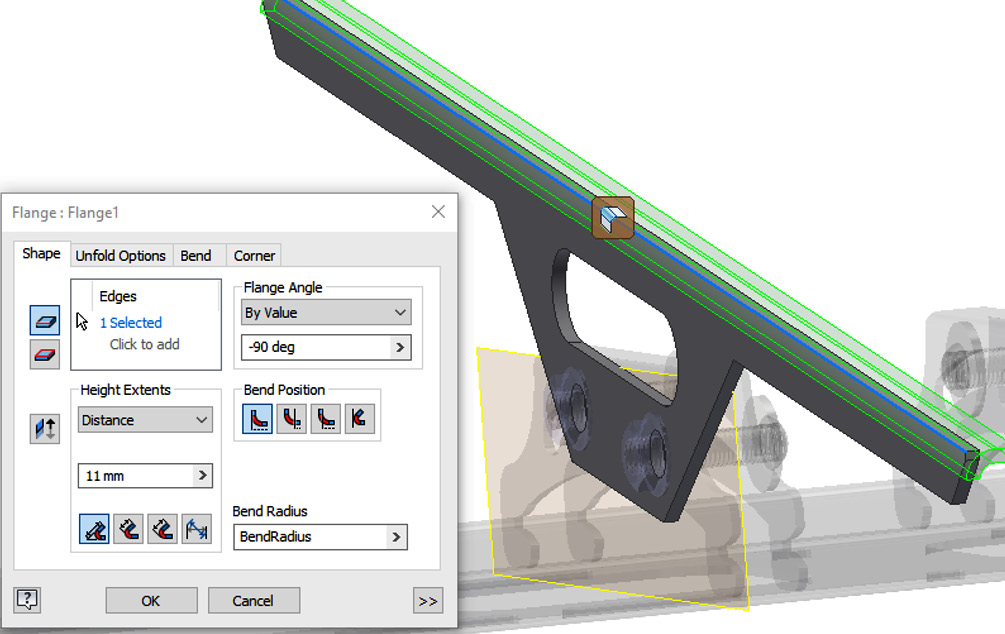
Figure 12.60: Flange applied to Face
- Select Mirror. Ensure Mirror features is selected. Then, select the face, flange, bolt holes, and slot cut previously created. For Mirror Plane, select the face shown in Figure 12.61. Select OK.
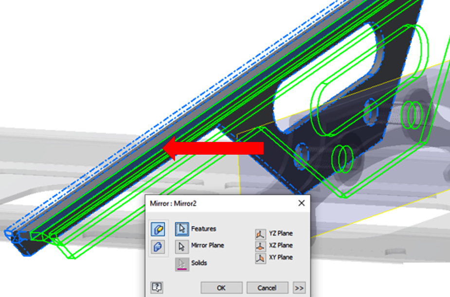
Figure 12.61: Mirror features applied to the previous face and flange created
- Select Corner Round from the Sheet Metal tab. Select the 12 corners shown in Figure 12.62. Set Radius to 4 mm and select OK to complete.

Figure 12.62: Corner Round applied to several corners of the sheet metal component
- Select Start 2D Sketch. Then, select the top face of the bracket as the plane. Sketch the geometry and points shown in Figure 12.63:

Figure 12.63: Top face of bracket and sketch to create
- Select Hole and apply the following three hole sizes to each point, as detailed in Figure 12.64:
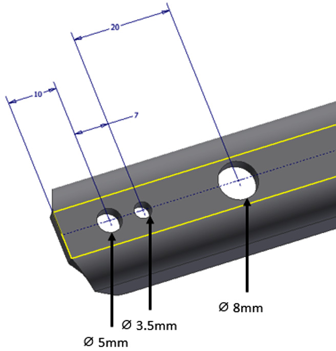
Figure 12.64: Holes to apply to the sheet metal part
Each hole has Simple set for the Hole type, and the Seat type is set to None. Only the diameter changes.
- Select Rectangular Pattern from the Sheet Metal tab. Select the three holes created in step 23 as the feature to pattern. Then, select the edge shown in Figure 12.65. For the spacing type, enter 50 mm. For the number type, enter 50 mm. Select OK to complete.
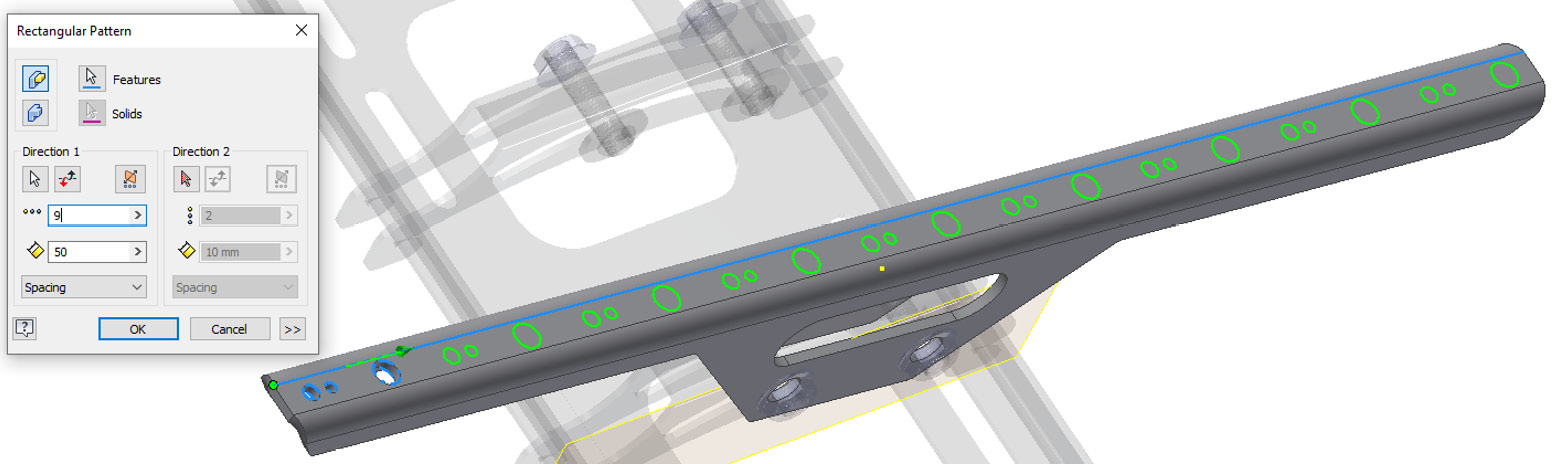
Figure 12.65: Edge to select for Rectangular Pattern, to create the desired number and spacing of holes
- Select Return to return to the assembly. The additional bracket component required (ArmBracket01) is now complete. We now need to duplicate ArmBracket01 for the other bolted connection in the assembly.
- Select the Assemble tab, then select Plane. From the dropdown, select Midplane between Two Planes.
- Select the face of the component shown in Figure 12.66. Select the same reverse face on the second instance of this identical component, also shown in Figure 12.66:
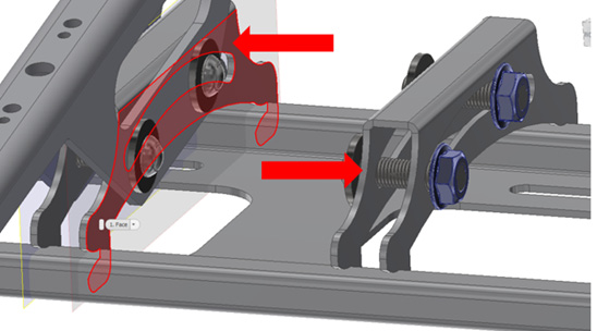
Figure 12.66: Mirror plane, reference planes to select
- Now that a new workplane has been created, select Mirror from the Assemble tab.
- Select ArmBracket01 as the component to mirror, then select the workplane created in steps 26 and 27 as the mirror plane. Select Next, then OK.
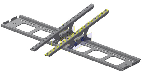
Figure 12.67: Completed TV wall-mounted bracket
- We will now generate a flat pattern of the new ArmBracket01 we created as part of the assembly and export this as a .dxf file for manufacture. In the Model Browser, right-click on ArmBracket01, then select Open.

Figure 12.68: Opening an instance of ArmBracket01
- Select Create Flat Pattern from the Sheet Metal tab. The sheet metal part is flattened into a flat pattern for manufacture:
- Select Bend Order Annotation to display the number of bends and the bend order
- Select Go to Folded Part to go back to the folded part
- Select Flat Go To Flat Pattern
Figure 12.69 shows the flat pattern of the bracket we created with the bend order displayed:

Figure 12.69: Flat pattern of ArmBracket01 with bend annotations
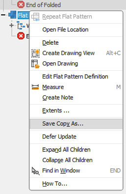
Figure 12.70: .dxf export of the Flat Pattern sheet metal part
- Set Save Type to .dxf. Select Save. Select the desired Export options, then select OK. This exports the flat pattern of the part as a .dxf file.
You have created an in-place sheet metal part in an assembly, with numerous sheet metal features, such as holes, cuts, faces, and flanges. You have then applied duplication techniques to replicate the repeating features and components in the assembly, generated a flat pattern of the completed component, and exported this as a .dxf file for manufacture.
Detailing sheet metal parts in the drawing environment
Inventor has specific detailing tools for sheet metal parts, which include bend tables and hole tables. The standard 2D detailing tools can also be used to communicate design intent on the design. Models can also be displayed on a drawing as flat patterns and folded parts.
In this recipe, you will learn how to generate a hole table and bend table and place folded/unfolded views of an existing sheet metal component within the drawing environment.
Getting ready
To begin this recipe, you will need to create a new ISO (mm) .dwg file.
How to do it…
First, we will import the views of a ready-made component in both the Folded and Flat Pattern states:
- Select Base.
- Select the Browse command and search for and locate Detail Sheet Metal.ipt in the Chapter 12 folder. Select Open.
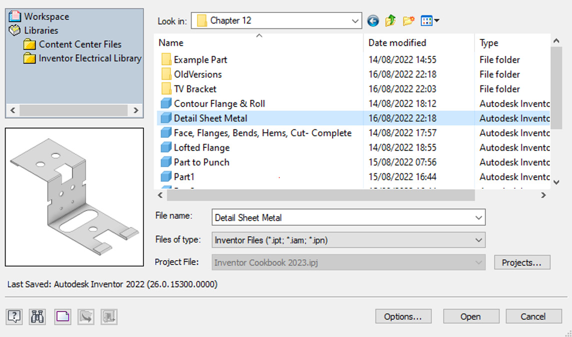
Figure 12.71: Detail Sheet Metal.ipt selected to apply a base view to a drawing
- You will notice that the Flat Pattern option is not available. This is because the flat pattern has not yet been generated in the part file. We will first place a view of the part in its Folded state. Drag the view to the top-right corner of the drawing. Then, select the top left of the view cube to display an Isometric view of the part. Select OK to apply the changes.

Figure 12.72: Isometric view of the folded sheet metal part
- Right-click on the isometric view placed in step 3. Select Open to open .ipt for this view.
- Select Create Flat Pattern. Then, select Save. Select OK and close .ipt.
- Navigate back to the drawing file. Select Base.
- Browse for Detail Sheet Metal.ipt. Select the file and then select Flat Pattern. Then, change Scale to 1:1. Place the view as per Figure 12.73 and select OK:
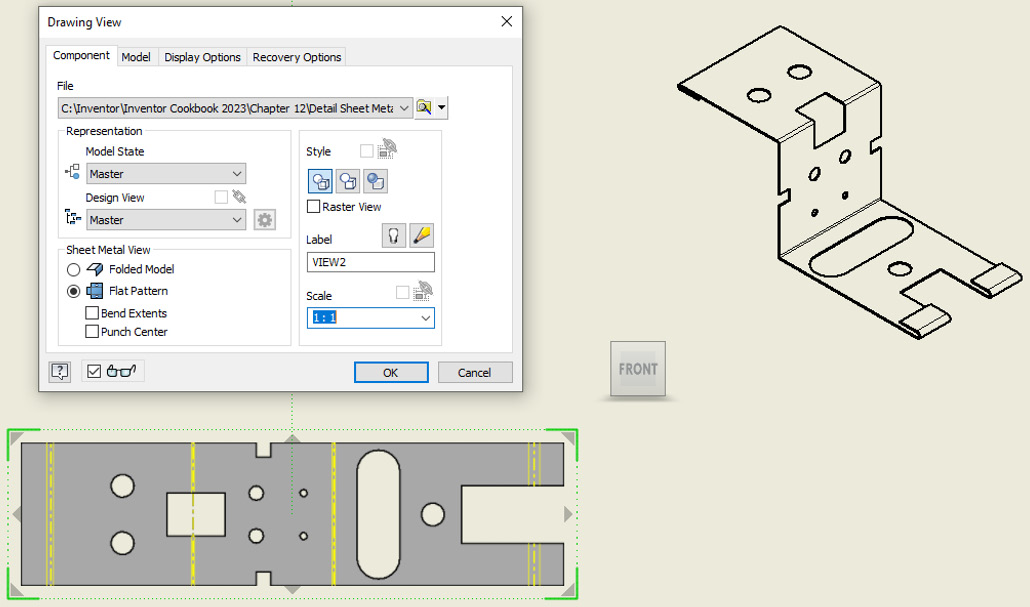
Figure 12.73: Flat pattern generated and placed on the drawing
- Select the Annotate tab, then select General from the ribbon in the Table commands.
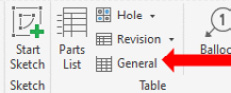
Figure 12.74: General table command
- Select the Flat Pattern view placed in step 7. The dialog preview populates with the column headings that the bend table will have. You can select Column Chooser to alter the column types if required, by adding or removing items. The bend table is reading information directly from the model’s iProperties, the same way a BOM table works.
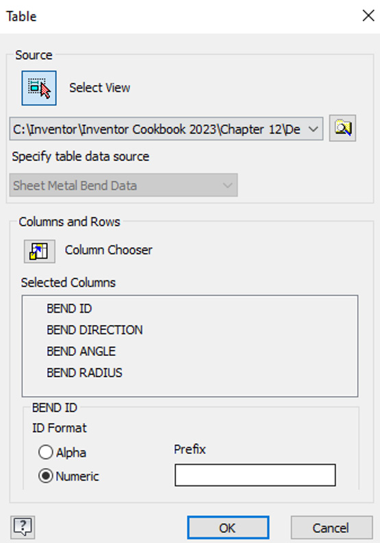
Figure 12.75: Bend table preview
- Select OK to place the bend table in the top left of the drawing.
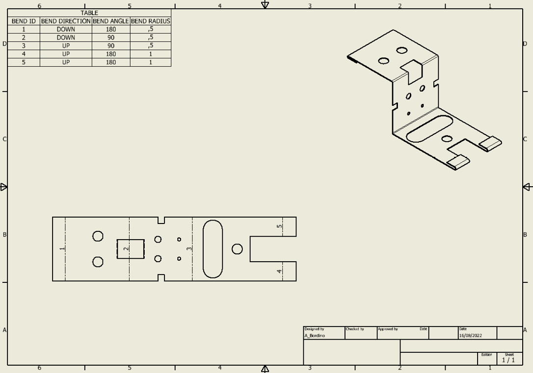
Figure 12.76: The bend table is generated
- The bend table is applied to the drawing. The Flat Pattern view is automatically edited to show corresponding Bend ID numbers that match the bend table. All information from the 3D model is displayed. We will now specify and generate a hole table. Select the dropdown next to Hole in the ribbon. Select Hole View.
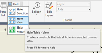
Figure 12.77: Hole View selected
- Select Flat Pattern View.
- Place the datum on the top right of the flat pattern view.
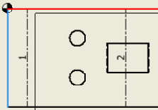
Figure 12.78: Datum placed
- Click under the bend table to place the hole table.
- Double-click on the generated hole table. Select the Formatting tab.
- Select Column Chooser. Select QUANTITY from Available Properties and select Add. Select OK, followed by OK again.
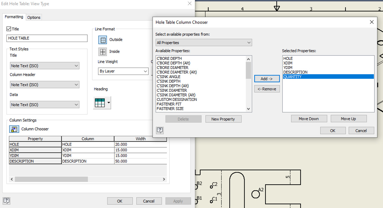
Figure 12.79: Hole Table Column Chooser
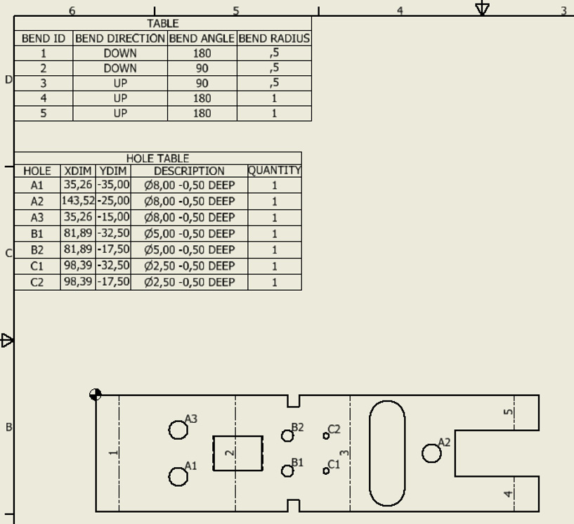
Figure 12.80: Sheet metal hole table and bend ID applied to the drawing
You have applied various views of a sheet metal component to a drawing, displaying both folded and unfolded states. You have also generated numbered bend tables and configured a hole table of the part in the drawing environment.
Model credits
The model credits for this chapter are as follows:
- Sheet metal tray (by Dileep Krishnadas K): https://grabcad.com/library/sheet-metal-tray-3
- VESA display wall-mount bracket (by Anindo Ghosh): https://grabcad.com/library/vesa-display-wall-mount-bracket-1