
3
Driving Automation and Parametric Modeling in Inventor
Automating aspects of the CAD design process should always be your target as an Inventor user. With automation techniques, the utilization of existing geometry and parameters, model updates, and design changes can be accomplished much more efficiently. By applying design intent with these features and methodologies early in the process, models will update and change as expected, without the need for extensive rework.
In this chapter, you will cover how equations and parameters are used to drive design intent in a model, and how to apply iMates, iFeatures, iParts, and iAssemblies to reuse existing digital features, parts, and assembly data throughout your designs.
In this chapter, we will cover the following topics:
- Reviewing equations and parameters in Inventor
- Creating equations and driving a model
- Creating parameters and driving a model
- Reusing design feature data with iFeatures
- Creating automatic mates using iMates
- Creating table-driven master parts to configure sizes and states with iParts
- Building an assembly of iParts with variations such as different sizes, shapes, and content using iAssemblies
Technical requirements
To complete this chapter, you will need access to the Chapter 3 folder within the Inventor Cookbook 2023 folder. This is the location of all recipe practice files for this chapter.
Reviewing equations and parameters in Inventor
Inventor equations help to enable the designer to incorporate intelligence and an element of design intent into the model. This ensures that as design changes are made to the design, the model updates and behaves as expected. Inventor equations are established through the creation of mathematical relationships between existing dimensions in a sketch or feature. They can also be established with parameters, which can also be user defined.
Equations sound much more difficult than they are; most of the time, a simple set of basic mathematical functions is required to produce the desired output. For more advanced automation and logic-based rules, iLogic would be incorporated. iLogic is the use of VB.NET code to run rules within Inventor to automate tasks and model updates. An understanding of the basic equations and parameters is fundamental to understanding iLogic. This chapter will focus solely on equations and parameters; more details about the workings of iLogic will be covered in Chapter 10, Inventor iLogic Fundamentals – Creating Process Automation and Configurations.
As you create and add sketches or features to a model, dimensions are generated. With each dimension that is created, Inventor automatically assigns a unique name to each one. The format of this is d, followed by a sequential number, starting from 0. Note that this resets with every new file that is created. Each time you create a new file, the first dimension name that Inventor will apply will always be d0 by default.
Equations use these d# dimension names to establish the desired relationships in the part. Once a value of one dimension is based on the function of another dimension in the model, the relationship is then known as an equation.
In general, the following steps are required to create an equation in a model:
- A base sketch or model is created, and dimensions are set to be displayed.
- Equations and relationships are created and established.
- The model is flexed to test the output. Flexing means changing parameters and dimensional values to see whether the resultant changes in the model’s behavior are as required.
- Edits are made, as required.
In the following recipe, you will apply parameters and equations within the context of an Inventor model.
Creating equations and driving a model
For this recipe, you will take an existing model, show the expressions and values already contained within it, and then add and create new equations to facilitate the required changes. The equations that you create will enable you to drive the model (make changes to it with the equations) to the desired outcome.
Getting ready
To complete this recipe, you will need to open the Housing.ipt file from the Chapter 3 folder.
To begin with, we will show the dimensions in the model at present, and then add equations to control the geometry to the desired output.
How to do it…
To begin this recipe, we will first look at what dimensions are present in Housing.ipt and examine the structure of the model. We will then proceed to apply equations. With Housing.ipt open, carry out the following steps:
- Right-click in any space within the Graphics Window and select Dimension | Display | Name. Then, right-click on Extrusion 1 and select Show Dimensions. This reveals the dimensions used to create this feature in the model. At present, just the default dimension names are shown, but we will now change this so that the dimension name is converted into a dimension expression.
- Click the left mouse button to clear the current selection. Then, right-click in the Graphics Window and select Dimension Display | Expression. The expressions for each dimension are now clearly shown, as per Figure 3.1:
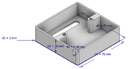
Figure 3.1: Dimensions as expressions shown on Extrusion 1 of Housing.ipt
- We will now add an equation so that the height of Housing.ipt is always 50 mm shorter than its width. Double-click on the d3 dimension. Enter the equation d1-25mm and hit Enter. Select Update if required. Select d1 and change the value to 85 mm. Select Update. The height of the Housing.ipt will change to 60 mm.
- Double-click on d1 and change the value to 45 mm. Update the model and see the changes. The equation in d3 is used again; this is shown in Figure 3.2:
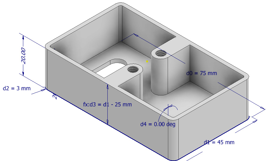
Figure 3.2: Expression and model updated to reflect the change of d1 to 45 mm
- We will now add an equation to drive the thickness of the Housing.ipt material. Right-click on Shell in Model Browser and select Show Dimensions. At this point, the default value for the thickness is 2 mm.
- Double-click the d5 dimension and add the following: d2-1. This controls the thickness of the part so that it is always the value of the radius of the model’s fillet minus 1.
- Now, we will flex the model to test this. Show the dimensions of Extrusion 1, double-click d2, and change this value to 4. Select Update and the thickness of the part will change.
Important note
Adding equations can be made as simple or as complex as desired. The full list of functions and controls can be found here: https://knowledge.autodesk.com/support/inventor-products/learn-explore/caas/CloudHelp/cloudhelp/2014/ENU/Inventor/files/GUID-69D04C7D-E195-49C0-B1B2-03C88A806D9D-htm.html.
- Viewing the range of equations in the model space can be quite limiting; fortunately, this can be managed far easier in the Parameters panel. Select the Manage tab, and in the Parameters panel, click the Parameters button.
The Parameters panel now opens, which contains a comprehensive list of all equations and dimensions in the model. Equations can be created here too.
There is nothing to change at present, but you can see that the equations added previously are now visible in the Parameters panel.

Figure 3.3: Parameters panel with new equations visible in the Equation column
The equations have now been created, so you can save and close the model.
You have now successfully created and applied equations to drive automatic changes in an Inventor part file.
Creating parameters and driving a model
In this recipe, you will use the Parameters panel to create equations and user-defined parameters. You will learn how to rename and organize parameters within a model and drive dimensions with them. You will also learn how to export parameters for use in another model as a reference parameter.
Getting ready
For this recipe, you will need to open the Heatsink.ipt file from Chapter 3 of the Inventor 2023 Cookbook project folder.
How to do it…
To start, we will examine an existing model that has no defined equations or parameters. The first task will be to access the Parameters panel and create these. To do this, take the following steps:
- Open Heatsink.ipt in Inventor. This part has been created and currently has no equations or user-defined parameters.
- Select Parameters from the Manage tab.
Here, we will now rename some of the existing parameters. You can also do this upon placing the dimension in the model space, but in this case, because the model is already created and defined, we will make the change in the Parameters panel.
- Select the d0 parameter and rename it to Length (be careful with naming parameters as they are case sensitive).
- Do the same for d1 and rename it to Width. Select the current value of 50 mm for Width and change this by typing Length. This now means that the width will always equal the value of the length. Because the values are currently the same, that is, both are set at 50 mm, the model will not make any geometric changes.
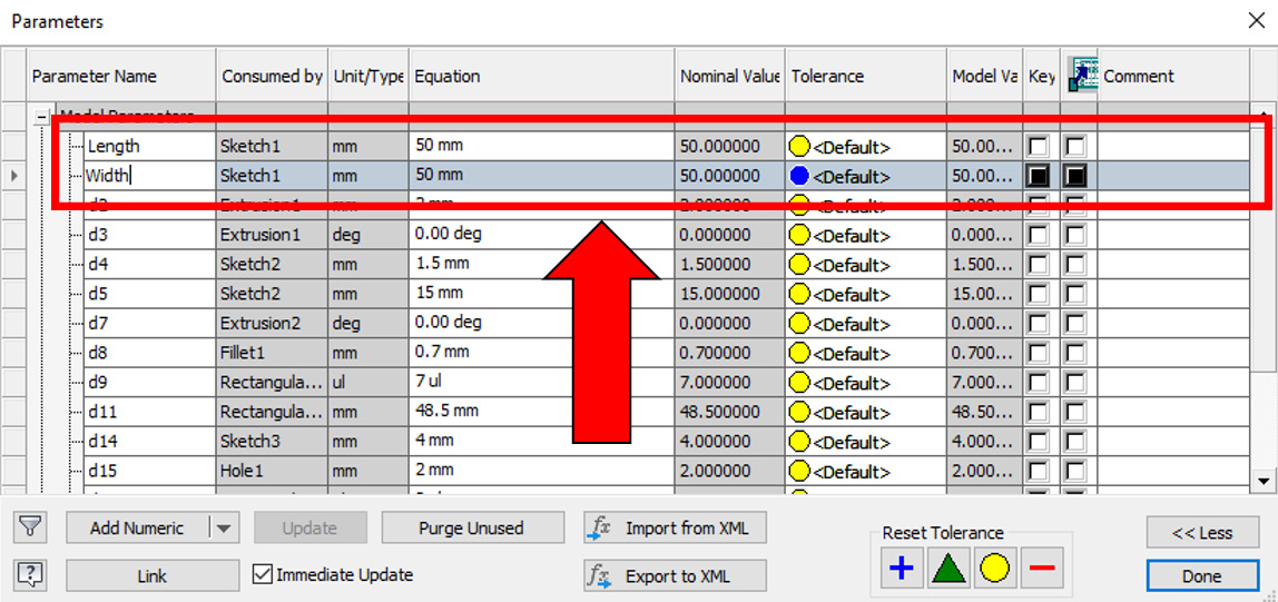
Figure 3.4: Width and Length parameters
- Exit the Parameters panel and select Start 2D Sketch on the face shown in Figure 3.5. Apply the sketch geometry shown in Figure 3.5, including the two sketch points spaced 6.4 mm from each other and the edge of the part. Then, click Finish Sketch.
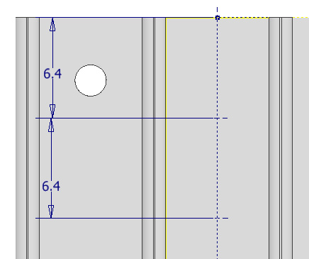
Figure 3.5: The sketch to be created
- Select the Parameters panel again.
- Rename the d37 parameter to Hole_Spacing. Then, select the tick box for Export of Parameter. This allows you to link this parameter to another Inventor model. Change the d38 parameter value to d37.
Ensure your equations match that of Figure 3.6 before clicking Done:
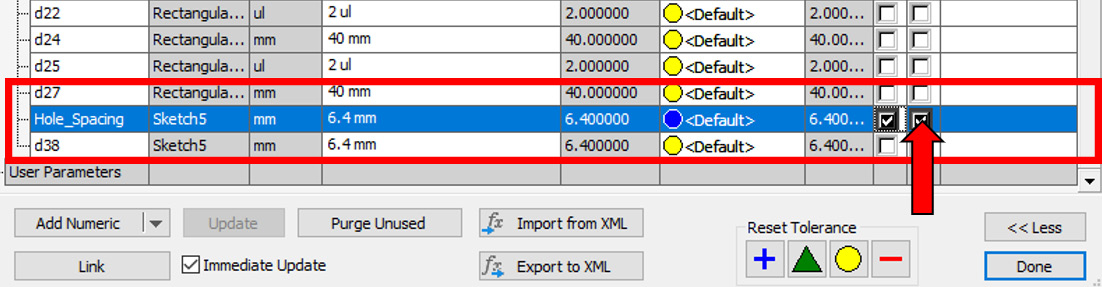
Figure 3.6: Renaming a parameter and selecting Export of Parameter
- Open Heatsink2.0.ipt from the Chapter 3 folder. Here, we will reference a parameter from the original Heatsink.ipt model.
- Right-click on Sketch5 in the Model Browser and select Edit Sketch. Add a dimension between all the preexisting sketch points (don’t worry about adding any specific values). An example is shown in Figure 3.7:
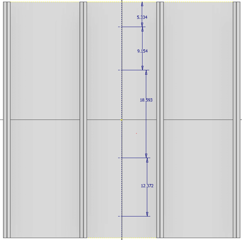
Figure 3.7: Dimensions added to sketch points in Sketch5 of Heatsink2.0
- Select the Parameters panel and click Link at the bottom left of the menu.
- Browse for the Chapter 3 folder and select Heatsink.ipt as the reference file.
- Scroll down the parameters to the Hole_Spacing option. Change the negative symbol to a positive one by selecting it. This notifies Inventor to import this parameter, as shown in Figure 3.8:
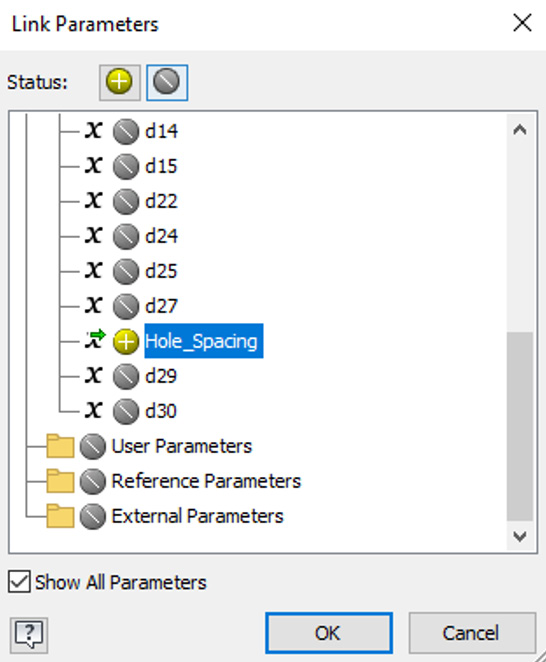
Figure 3.8: Parameters to import into Heatsink2.0 from heatsink
- Select OK. The imported parameters now appear in the Parameters dialog.
- Change the Equation value of dimensions d37 to d40 to Hole_Spacing, as per Figure 3.9:
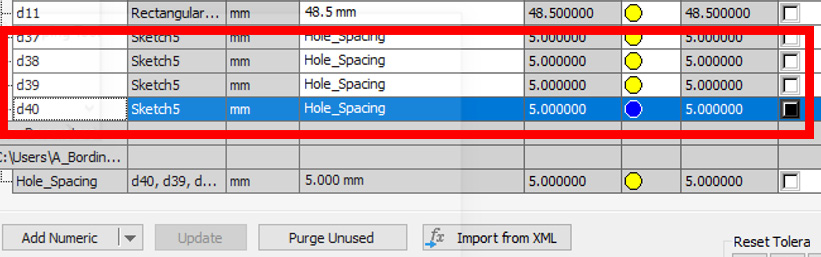
Figure 3.9: Linked parameters changed in the Heatsink2.0 file
- Select Done. The sketch points created are now showing the same hole spacing dimension and value as the original Heatsink.ipt file.
- Select the Hole command from the 3D model. Then, apply a hole as per the specifications in Figure 3.10 to the sketch points in Sketch5:
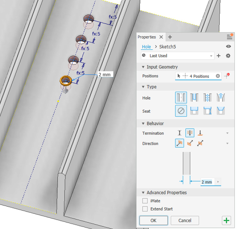
Figure 3.10: Hole feature to be created
Now, we will make a change in the Heatsink.ipt file and see how the parameter in Heatsink2.0.ipt is updated.
- Open Heatsink.ipt. Then, in the Manage tab, select Parameters.
- Change the Hole_Spacing value from 5 mm to 10 mm. Select Done.
- Open Heatsink2.0.ipt and review the changes that have been made from the original file where the parameter was exported. You may have to select Local Update to review the changes. Once the change is complete, you will see how the hole spacings in Heatsink2.0.ipt have also increased to 10 mm.
Heatsink2.0.ipt will show the same parameter changes as Heatsink, demonstrating the linking and exporting of a parameter function. Save both files as they are now both linked.
You have created a custom parameter to drive hole spacing in one part, and then exported a link to this parameter to control the hole spacing of another independent part.
Reusing design feature data with iFeatures
iFeatures are a method of copying and reusing design features between files. This duplication technique is an effective way of reusing existing feature design data throughout your models, without needing to remodel features each time. iFeatures can be added to a single part or across multiple parts. Once created, an iFeature is cataloged in a library for future use. iFeatures can be fully parametric with both the size and position driven by parameters.
Using iFeatures effectively enforces consistency in designs and saves time. The typical process of creating an iFeature is as follows:
- The iFeature is created in a part file.
- Features are selected for iFeature export.
- Parameters are established.
- The iFeature’s position is defined.
- The iFeature is saved in the relevant library.
- The iFeature is imported, configured, and placed in a model.
In this recipe, you will create a new iFeature of a plastic boss for use in another plastic casing product to complete the part. The iFeature will be defined with a configurable table of options. It will then be exported from the parent file, and then imported, placed, and configured in the new independent model.
Getting ready
For this recipe, you will need to open the Casing.ipt file and the Boss.ipt file from the Chapter 3 folder in the Inventor 2023 Cookbook folder.
How to do it…
We will start with an existing file that contains the feature that we want to export into another model. Then, we will create an iFeature of this for exporting and importing into the desired target location. To do this, take the following steps:
- Open the Boss.ipt file. You will see that this feature has already been created for you. This is the feature we will convert into an iFeature and export for use in another model, Casing.ipt in this example.
- Navigate to the Manage tab and find the Author panel. Then, select Extract iFeature.
- The Extract iFeature menu now appears on screen. This prompts you to select the features from the Model Browser to include as part of the iFeature. Select Extrusion 1.
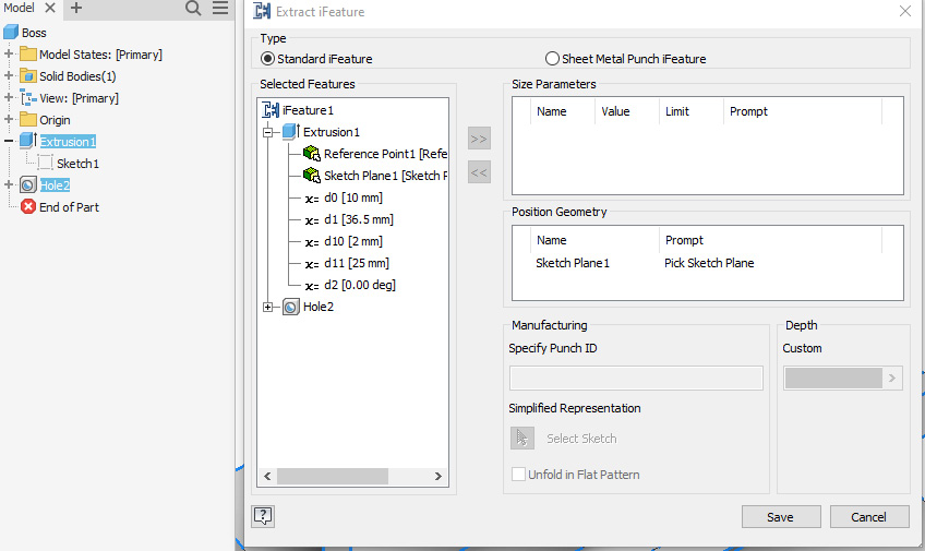
Figure 3.11: Extract iFeature dialog
Extrusion 1 is added, as are all the child features of Extrusion 1. This is shown in Figure 3.11. Note that the custom parameters that have been created for Height and Diameter are also pulled across and can be configured here too.
- The custom parameters have already been defined. We will now set various values and limits as well as prompts so that the placement of the iFeature for future users is clear. The purpose of this is so that the user will simply have to click a face to place the iFeature on it.
- Click the iFeature(#) text in the Extract iFeature window and rename it to iFeatureBoss. This will make finding and reusing the iFeature in the future much easier, as it now has a meaningful name, as opposed to the default one.
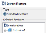
Figure 3.12: Newly created iFeature renamed
- Select Save. You will be prompted to save in the Catalog folder. Create a new folder here called iFeature. Save your iFeature in the iFeature folder as iFeatureBoss.ide.
- Then, navigate to the Catalog folder: C:UsersPublicPublic DocumentsAutodeskInventor2023Catalog<yourname>folder.
- Find the iFeatureBoss.ide file just created and open it. From here, we will now configure the options available to the user upon placement of the iFeature in a model.
- Select the iFeature Author Table icon in the ribbon.
- You are now prompted to configure the parameters you would like to drive the iFeature and the configurations that will be available to the user upon placement. In this example, we will create three variations of the boss with various sizes of Height and Diameter. Right-click on the first row of the table and select Insert Row. Repeat this again so there is a total of three rows. This is shown in Figure 3.13:
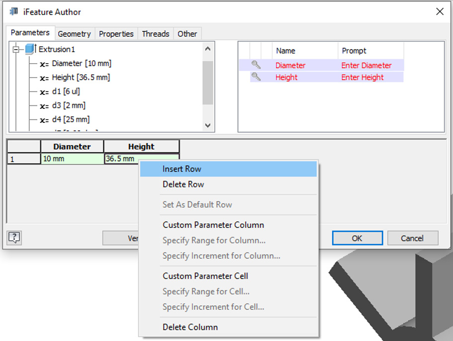
Figure 3.13: Insert Row
- Click the key icon in the right-hand side box and change both keys so they are blue and active.
- Change the Prompt text to Select Diameter and Select Height, as shown in Figure 3.14:

Figure 3.14: Prompts changed and key selected
- Select the text in the tables and change the options so they match those in Figure 3.15. These will be the Height and Diameter options the user can pick and select upon placement of iFeatureBoss.
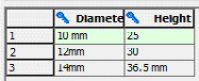
Figure 3.15: Diameter and Height options required
- Select Verify to check that the values entered are compatible. Select OK, save the iFeatureBoss.ide file, and close the file.
- Open the Casing.ipt file. We will now import the newly created iFeature and place a boss feature to improve the structure and provide a fixing point to the plastic casing design.
- In the Manage tab, navigate to the Insert environment and select Insert iFeature.
- Browse for the iFeatureBoss.ide file that was recently created and select Open.
- iFeatureBoss will be visible in the preview on the cursor, and Inventor prompts you to pick a sketch plane to place the iFeature. Select the position shown in Figure 3.16:

Figure 3.16: iFeature placed on Casing.ipt
- Once placed, click Next.
- Then, click on the 10 mm value of Diameter and change it to 12mm. Upon changing Diameter, the iFeature updates Height to 30 mm as per the values originally detailed in the table in Figure 3.15.
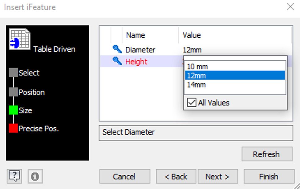
Figure 3.17: iFeature configured and selected, driven with values from the table
- Select 12mm as the diameter. Then, select Next and then Finish. The table-driven configured iFeature is placed on the part.
- Complete the model as per Figure 3.18 by adding two more identical iFeatures to the locations shown. Repeat the Insert iFeature steps to accomplish this.
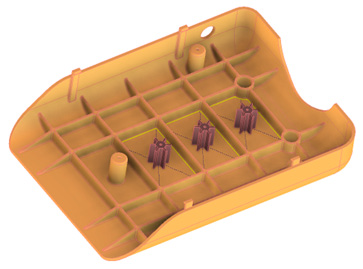
Figure 3.18: Completed model with duplicate iFeatures added and the locations illustrated
You have successfully created and exported a table-driven parametric iFeature, selected a configuration, and then imported this into a new model. Casing.ipt does not link to iFeatureBoss.ide. These are separate independent files and are not linked.
Creating automatic mates using iMates
iMates are used in Inventor to work more efficiently in part designs when putting them together into a top-level assembly. The iMate functionality enables you to place and mate components in place automatically in an assembly. This is very useful if there are several repeating components in an assembly when identical mates are required. iMates have the constraint information stored within, so manual mates are no longer required with that component. iMates can also be combined into an iComposite so that parts that require multiple Mate constraints can be assembled automatically.
This also makes it easy to create interchangeable components within an assembly. If the same iMates are configured for each component within the assembly, they can be swapped out automatically and changed with the iMate functionality.
In this recipe, you will complete an assembly of a drone using iMates to automatically complete the assembly. iComposites will be created, configured, and applied to components and then automatically applied to build and complete the drone.
Getting ready
To begin this recipe, you will need to browse and access the Inventor Cookbook 2023 folder | Chapter 3 | Drone, and then open the DRONE.iam file.
The completed model, once the iMates have been applied, is shown in Figure 3.18:
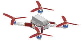
Figure 3.19: The completed DRONE.iam assembly
How to do it…
We will start with an incomplete drone assembly, and then proceed to build in iMates to complete the assembly as per Figure 3.19. To do this, take the following steps:
- Open the DRONE.iam file; Figure 3.20 shows what it looks like. The assembly of the drone is complete, except the Motor and Blade components are missing from the model. We will use iComposites/iMates to automatically configure this upon placement.
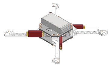
Figure 3.20: The DRONE.iam file open with missing components
- We will now begin to configure the first composite iMate. A matching iComposite must also be applied to the other target component for the mate to automatically constrain and place. Start by navigating to the browser, then right-click on the spider arm:1 file and select Edit. You are now editing the part within the context of the assembly.
- Navigate to the Manage tab and select the iMate button from the Author panel.
- The Create iMate window is now active. Next, we must specify the first iMate to apply. Select Insert as the type of constraint and select the geometry shown in Figure 3.21. No offset is required in this instance.
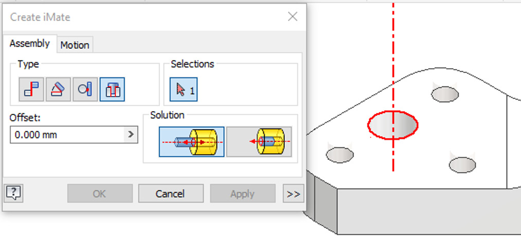
Figure 3.21: Mate constraint and geometry required for this iMate
- Select Apply. The insert iMate has now been created. Note in the Model Browser on the left-hand side that an iMates folder has now appeared. Expand this by clicking the + icon next to it. You will see the iMate has been configured. By clicking on the default iMate name, the name can be changed, but in this instance, leave it as the default.
- Right-click the iMate in the browser and select Create Composite. An instance of iComposite 1 is created. (If more iMates were required, these could also be added to the iComposite or group. iComposites can also be renamed if required.)
Now that this iComposite has been created, we will need to replicate this in the target component that we want to mate with the spider arm. Figure 3.22 shows the iComposite after creation:

Figure 3.22: iComposite iMate created in the spider arm file
- Now the iComposite iMate has been created for the spider arm. There are multiple instances of the spider arm in the assembly. Because of this, the iMates created in the previous step have been generated in the duplicates also, as they share the same source file. Select Return from the far right of the ribbon to return to the assembly and exit Edit Part mode.
- Save the assembly at this point.
- Open the MOTOR.ipt file from the same folder as DRONE.iam. The corresponding iComposite/iMate needs to now be created.
- Select the Manage tab, then iMate, and place an insert iMate on the geometry of MOTOR.ipt, as shown in Figure 3.23:
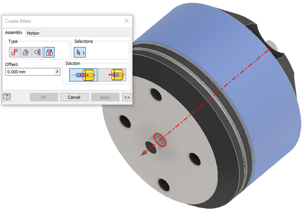
Figure 3.23: Insert iMate to be created on MOTOR.ipt
- In the Model Browser, under the iMates folder, right-click on the insert iMate you just created and select Create Composite. The iMate is converted into an iComposite with the same name as the spider arm component, as shown in Figure 3.24. This is crucial as Inventor uses iMate and iComposite names to match and create the automatic mating.

Figure 3.24: Insert iMate as part of an iMate iComposite in MOTOR.ipt
- Save and close the MOTOR.ipt file.
- Open DRONE.iam.
- Select Place from the Assemble tab.
- Pick MOTOR.ipt and ensure that the Interactively place with iMates icon is active. See Figure 3.25. If this is not active, the component will not be placed using iMates or iComposites.
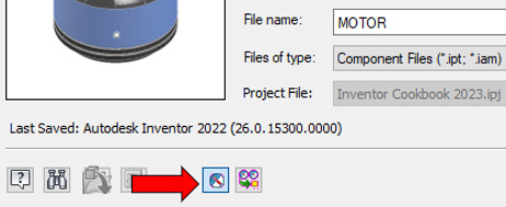
Figure 3.25: Interactively place with iMates glyph selected
- Select Open.
- MOTOR.ipt will automatically mate with the spider arm, as per the iComposite defined previously. Note the green iComposite glyphs in the Graphics Window that are highlighted. To place the part automatically on location with the iMate, left-click in the Graphics Window.
- MOTOR.ipt has now been automatically constrained with the iMate. This will cause you to be zoomed into the model by default. Zoom out from the model with the mouse wheel without deselecting anything. Note that the second instance of the motor on the corresponding arm is already in place to be added to the assembly.
- Continue to left-click until all four instances of MOTOR.ipt have been added to the assembly and placed with the iMates. Figure 3.26 shows the completed stage:

Figure 3.26: All four MOTOR.ipt parts placed in the assembly with iComposite1
We will now repeat this process for the remaining components.
- Open Spinner.ipt from the Drone folder.
- Create another insert iMate, as shown in Figure 3.27:

Figure 3.27: Spinner.ipt with iMate created
- Once created, right-click on the iMate in the browser and then click Create as an iComposite. Rename the iComposite created to iComposite:2 and the insert iMate to Insert:2, as shown in Figure 3.28:

Figure 3.28: iComposite:2 created
- Save and close Spinner.ipt.
- Open DRONE.iam
- In the Model Browser, right-click MOTOR.ipt and select Open. Create an insert iMate, as shown in Figure 3.29:
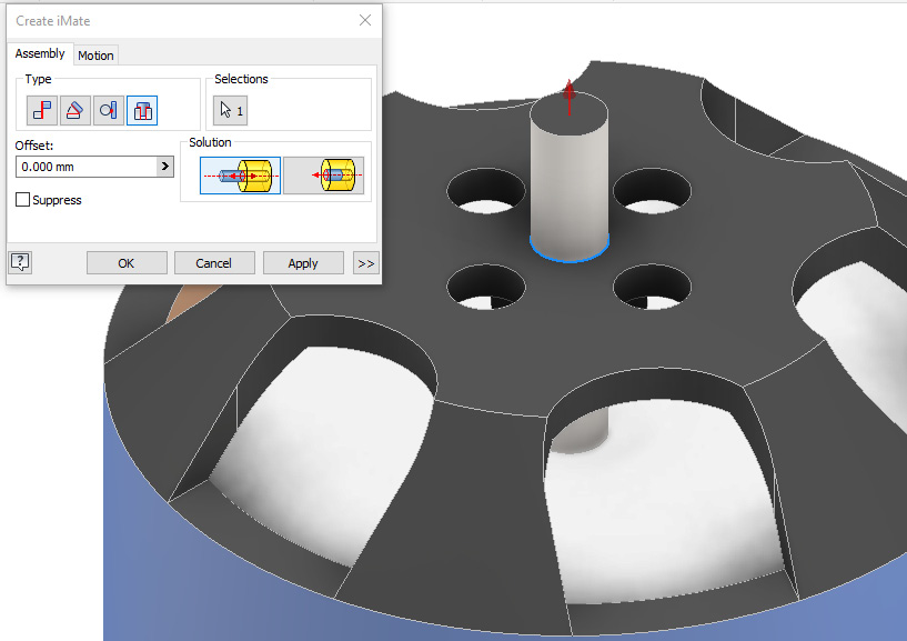
Figure 3.29: Insert iMate created in MOTOR.ipt
- Once created, create an iComposite from the iMate in the previous step and rename it iComposite:2. Then, rename the insert iMate to Insert:2. The text must match the previous iComposite/iMate to function. This should result in two iComposites in the MOTOR.ipt file. Save MOTOR.ipt.
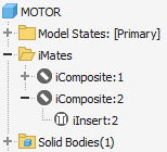
Figure 3.30: Two iComposites in MOTOR.ipt
- In the Assemble tab, select Place and then select Spinner.ipt. Ensure the iMate glyph is selected.
- Left-click and place the four instances of Spinner.ipt on DRONE.iam. The completed step is shown in Figure 3.31:

Figure 3.31: Four instances of Spinner.ipt added to DRONE.iam with iComposites
- Save the assembly.
- Open Fan.ipt from the Drone folder.
- Create the insert iMate as shown in Figure 3.32:
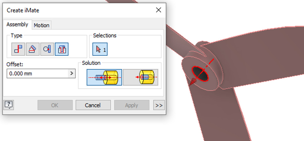
Figure 3.32: Insert iMate required
- Create an iComposite of the iMate and rename it as per Figure 3.33:

Figure 3.33: iComposite renaming required
- Save and close fan.ipt.
- Open DRONE.iam.
- In the Model Browser, right-click one of the spinner components and select Edit to edit the part inside of the assembly.
- Create and apply the following iMate shown in Figure 3.34:

Figure 3.34: iMate to be created on Spinner.ipt
- Create an iComposite of the iMate just created and rename it iComposite:3. Rename the iComposite and insert iMate to iComposite:3 and iInsert:3, respectively. Select Save and then return to the assembly.

Figure 3.35: Third iComposite to create
- Place the instances of fan.ipt using the iComposites. Figure 3.36 shows the result:
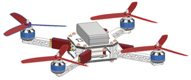
Figure 3.36: All fan.ipt instances added to DRONE.iam
- To complete the model, add a final iComposite 5 with a single Insert on the prevailing torque hex nut_am_AM-M4-N.ipt. The end assembly should look as in Figure 3.37:
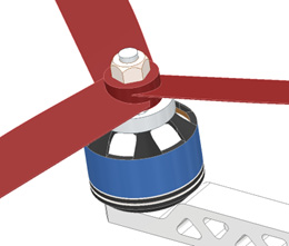
Figure 3.37: Completed DRONE.iam
The assembly is now complete. You have successfully created a range of iMates and iComposites to automatically apply the remaining components to complete the assembly of a drone.
Creating table-driven master parts to configure sizes and states with iParts
iParts enable you to create variations in part designs quickly and efficiently. In some cases, you may have a part that is similar to other parts you manufacture, yet only with slight variations. The iPart functionality creates variations or members within the same part file, which can be selected and generated. This means that similar parts do not need to be repeatedly created from scratch. Once a part has been created with iPart members, these members can be documented in a drawing file as a table.
For this iPart recipe, we will create an iPart of an existing bracket already modeled. The iPart will enable the creation of several variations of the bracket.
Getting ready
To begin this recipe, you will need to browse and access the Inventor Cookbook 2023 folder | Chapter 3 and then open the Bracket.ipt file.
How to do it…
For this iPart recipe, we will create an iPart of an existing bracket already modeled. The iPart will enable the creation of several variations of Bracket.ipt. To do this, take the following steps:
- Open Bracket.ipt. This is a simple bracket containing a central bore, supporting ribs, and four fixing holes. Open the Parameters panel, as shown in Figure 3.38:
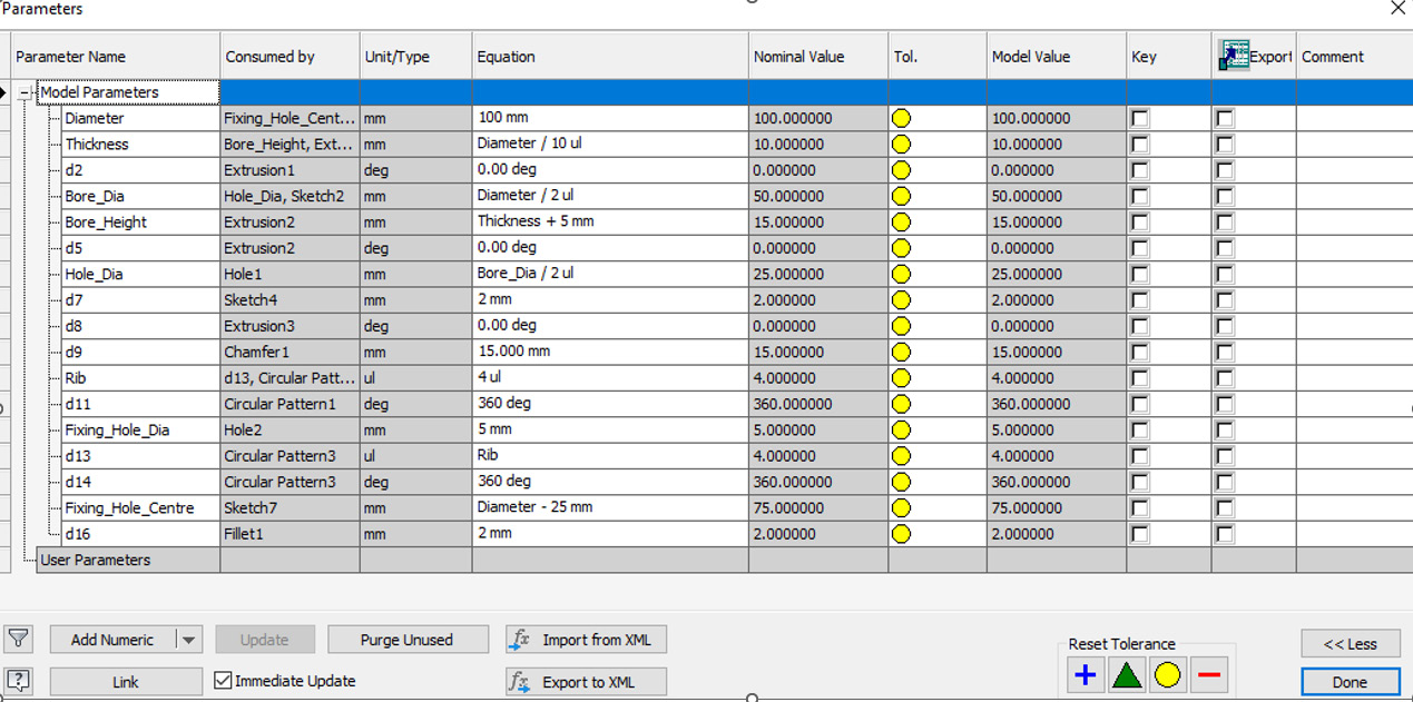
Figure 3.38: Parameters for Bracket.ipt shown
The model parameter names have already been changed, and the relevant equations have been applied. This is so that the model updates as required. To test the equations and parameters already applied, change the value of Diameter to 150 mm and then 200 mm, and observe how the model updates. Note how the diameter changes in the model.
- Now change the Diameter parameter back to 100 mm. The part updates and the original design configuration is restored, but with iParts, we can enable greater differentiation between size variants and set these as absolute values that can be picked by the user. This can be achieved without the need to manually edit the Parameters table.
- In the Manage tab, open the Author panel and select Create iPart.
The iPart Author menu now opens. Note all the custom parameters have automatically been included in the iPart.
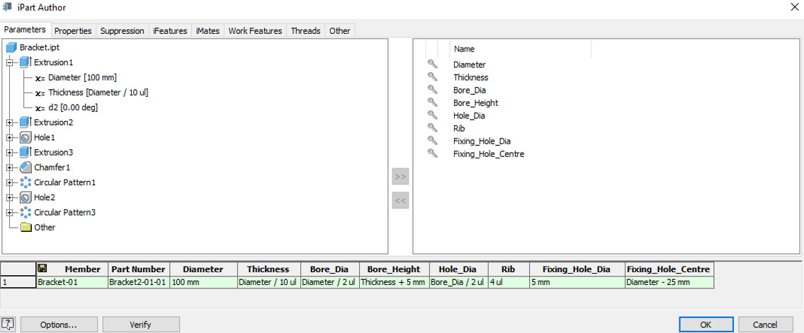
Figure 3.39: iPart Author menu
- As we want to create five variants (or members) within this iPart, move the cursor over the first line of the table, right-click it, and select Insert Row. Build five rows in the table, which will form the basis of five iPart members.
- Now, we will differentiate between the members. Change the values in the Diameter, Rib, and Fixing_Hole_Dia columns by clicking on the text in the table and typing so that they match those shown in Figure 3.40:
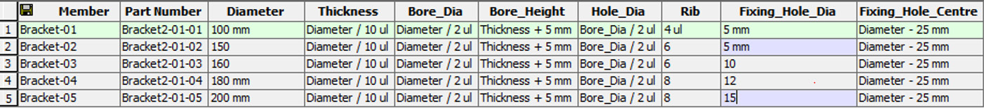
Figure 3.40: iPart member changes required
- In the Key area of the menu, select the following parameters as key parameters to update and change the iPart. You can add up to nine keys in an iPart configuration. The purpose is to allow for easier organization and a logical/hierarchical structure for the configurations. Ensure your menu on screen matches that of Figure 3.41:

Figure 3.41: Keys selected
- With the keys now assigned, select Verify. The iPart author checks the values added and ensures your model can compute them.
- Select OK. The iPart Author menu closes and you are returned to the base part.
- In the Model Browser, you will notice a Table icon has now appeared. Expand this, as in Figure 3.42:
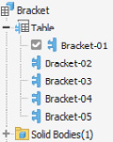
Figure 3.42: iPart table expanded in Bracket.ipt
Note that the iPart members created are now visible. The active one in this instance is the member with a 100 mm diameter. The active member is visible in the Model Browser as it has a tick mark next to it, as shown in Figure 3.42.
- Double-click the other members and observe how the model updates. The bracket will update based on the values you entered in the iPart creation. Various configurations can now be generated automatically.
- Additional features are required on Bracket-05. Double-click on Bracket-05 to activate it. Then, in the Manage tab, open the Author panel and select Edit Member Scope. We can now make changes to this individual member of the iPart.
- Add a 2 mm fillet to the edge of the central hole. Then, add a thread, as detailed in Figure 3.43, to the same hole:
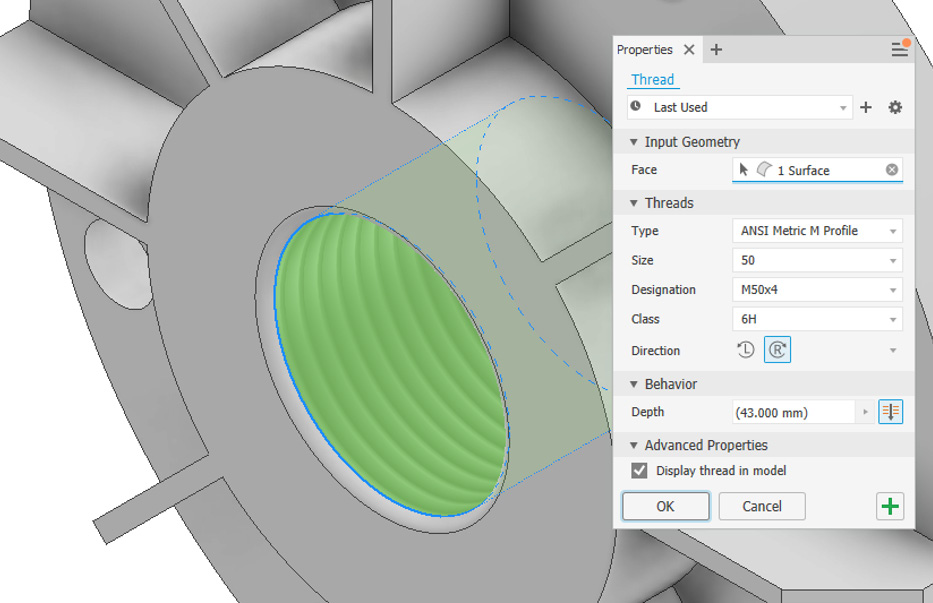
Figure 3.43: A 2 mm fillet and thread added to Bracket-05, in Edit Member Scope
The changes have only been made to Bracket-05 as desired.
iPart changes using Excel
You can also create changes and manipulate an iPart table using Excel. By right-clicking on an iPart table, you have the option to edit via a spreadsheet.
- Activate the Bracket-01 member.
- We will now generate separate part files for each iPart that has been defined. Hold Shift and select all the iPart members. Then, right-click and choose Generate Files.

Figure 3.44: How to generate files from the members created
Save the files if prompted.
- Select Open within the Chapter 3 folder. A new Bracket folder has been created to store all of the separate .ipt files from the iPart generation. We will now import and use the iPart in an assembly.
- Create a New Standard (mm) .iam assembly file.
- Select Place, then select the Bracket.ipt file from the browser, followed by Open.
- You are now prompted to select the iPart member you wish to import into the assembly. Choose a configuration you would like to import. Select OK.
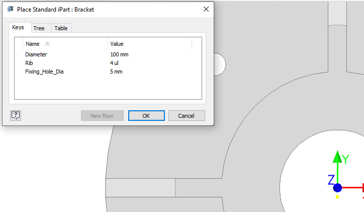
Figure 3.45: Placement of a standard iPart in the assembly
The configured iPart member is imported into the assembly.
- Close and do not save the assembly file.
You have successfully created an iPart with several configurations, edited an individual member, published the configurations as a table-driven iPart, and imported this into an assembly for use.
Building an assembly of iParts with variations such as different sizes, shapes, and content using iAssemblies
iAssemblies are used to create variations of assemblies and subassemblies that make up your designs. They are an efficient way to create configurations of assemblies, in a single file, without the need to recreate and duplicate work. iAssemblies work and are configured in a similar way to iFeatures and iParts.
Configurable attributes in an iAssembly can consist of suppressing or computing features/parts, constraint values, materials, appearance, and even the BOM structure of components. In most cases, the following steps are used to create an iAssembly:
- Standard parts are assembled into an assembly.
- iParts are configured from the parts in the assembly (this can be done prior to being placed into the assembly).
- The creation of an iAssembly is initiated.
- Configurable attributes and iAssembly members are specified from the iParts or sub-iAssemblies.
- The iAssembly is verified.
If the iAssembly contains a subassembly, this will also need to be created as its own independent iAssembly.
In some cases, when creating an iAssembly from existing assemblies, normal parts must be replaced with their iParts. Sometimes, existing mate constraints can become unresolved and will either need to be recovered or reapplied. iAssemblies can also be placed into other assembly files for future use and, once placed, can be configured on demand.
In this recipe, you will create an iAssembly of a premodeled screwdriver so that you can vary the length of the handle and shaft. This is a simple take on an iAssembly but will reveal the steps required to create and configure one. (iAssemblies can become much more complex if required.) To start with, you will create two iParts from existing components and then combine the two into the iAssembly.
Getting ready
To begin this recipe, you will need to browse and access the Inventor Cookbook 2023 folder | Chapter 3 and then open the ScrewDriverAssy.iam file.
How to do it…
Within the assembly, we will first have to make separate iParts, before proceeding to combine these into an iAssembly. To do this, take the following steps:
- Open ScrewDriverAssy.iam. The assembly is fully constrained, but the parts within it are standard parts, not iParts.
- Right-click on Handle.ipt in the Model Browser, then select Open.
- The iPart for the handle now needs to be created. The parameters required to change the length of the handle as desired have already been applied. So, select Create iPart from the Author panel.
- Select the Length [150mm] parameter from the Parameters list in the iPart Author window.
- In the iPart Author window, select the key symbol on the Length parameter.
- Right-click on the first line of the table, then click Insert Member. Repeat this to create a total of three members in this iPart.
- Rename the members and part numbers, and then change the length to the values shown in Figure 3.46:

Figure 3.46: iPart Author window active with required Member, Part Number, and Length values
- Select Verify, then OK.
- The iPart members have been created in the file. Expand the iPart Table node in the Model Browser and double-click on each member to update the Handle part. Observe how the length changes in Figure 3.47:
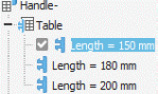
Figure 3.47: iPart table created with the three length variations
- Double-click and activate the Length = 150 mm iPart member so that it is active.
- Hold Shift and select all members in the Model Browser. Then, right-click and select Generate Files, as shown in Figure 3.48:
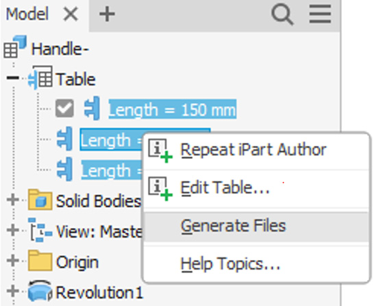
Figure 3.48: Generating the files from the iPart members
Save the file if prompted.
- Close the Handle.ipt file.
- Open the ScrewDriverAssy.iam file.
- A local update is required on the model. Select the Update button to activate the update, as shown in Figure 3.49:

Figure 3.49: Local update button location
The Handle iPart is now showing in the assembly, but if you attempt to double-click on the various members, the part will not update. The component needs to be replaced with the new version of itself in the assembly.
- Right-click Handle in the Model Browser, then select Component | Replace.
- Browse for Handle.ipt and select Open.
- Inventor now prompts you to select the desired iPart value to be imported into the assembly. Leave this as 150 mm. We have yet to define the Shaft component and convert the assembly into an iAssembly. Select OK.
- Upon completion, an error will flag. This error states that one of the insert Mates is now unresolved and needs attention to proceed. You can see this from the warning triangle in the Model Browser.
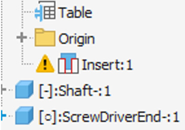
Figure 3.50: Unresolved mate constraint warning
We now need to solve this error. Right-click on the Insert:1 mate, then select Edit.
- We can now reapply the mate to resolve the issue. Pull the Shaft component away from the handle by clicking and dragging it; this makes editing the mate easier.
- Select the Insert Mate and apply it as shown in Figure 3.51. Select OK, and the mate is resolved.
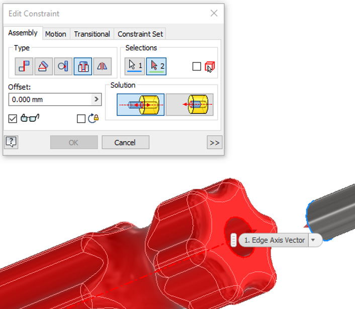
Figure 3.51: Insert Mate to be redefined
- This process now needs to be completed for the second iPart of the iAssembly: Shaft.ipt.
- Right-click on Shaft from the Model Browser in the ScrewDriverAssy.iam file. Then, click Open.
- Select Create iPart. Select Length [165mm] as the parameter.
- Assign the key to Length. Insert two more rows/members on the table.
- Change the values of the table as per Figure 3.52:

Figure 3.52: Changes required to the Member, Part Number, and Length parameters for the iPart configurations of Shaft.ipt
- Select Verify. Select OK to finish.
- Hold Shift and select all three members of the Shaft.ipt iPart. Then, right-click and select Generate Files, as per Figure 3.53:

Figure 3.53: Generation of files from the Shaft iPart
- Save and close Shaft.ipt. Then, open ScrewDriverAssy.iam.
- Perform a local update on the file. In the Model Browser, right-click Shaft, then select Component | Replace.
- Browse in the Chapter 3 folder for Shaft.ipt and select Open. Leave the default value as 165 mm and select OK.
- Accept the unresolved mate constraints.
- Open the Shaft node in the Model Browser and note the unresolved mates, as shown in Figure 3.54. We will need to rectify an error in the mates once more.
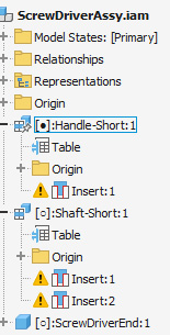
Figure 3.54: Unresolved mates as a result of a Component | Replace operation with Shaft.ipt
- Right-click on Insert:1, then click Edit.
- Pull the two components away from each other with a mouse drag and reapply the Insert Mate, as per Figure 3.55:
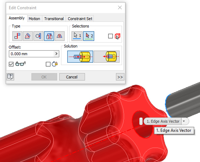
Figure 3.55: Insert:1 mate to be reapplied
- Repeat the process for Insert:2, as per Figure 3.56:
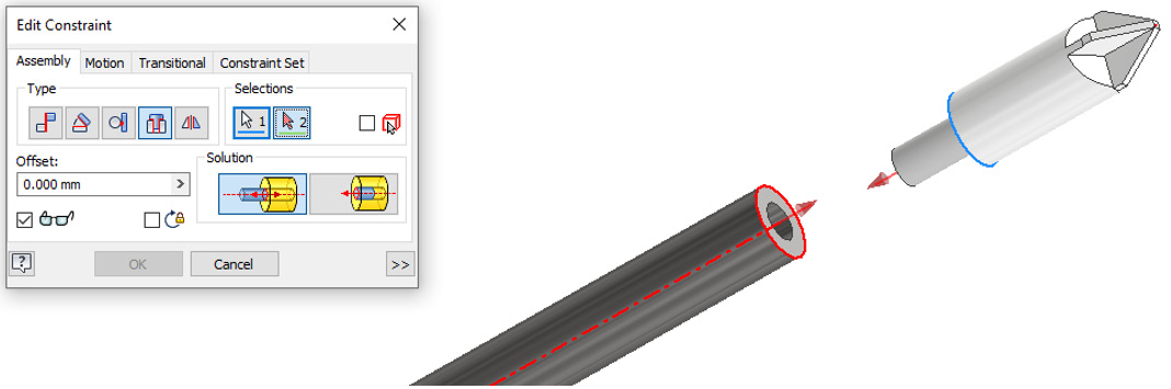
Figure 3.56: Insert:2 mate to be reapplied
- The mates have now been resolved, and the iParts are completed and imported into the assembly. We now need to convert the assembly to an iAssembly and link the two iParts together. Select Create iAssembly from the Manage tab.
- Select Handle-:1:Table Replace from the right side of the menu and select the >> button to move it across to the left.
- Repeat this for Shaft-:1:Table Replace. The result of this should be that both Handle-:1:Table Replace and Shaft-:1:Table Replace have been moved to the right-hand side of the window, as per Figure 3.57:

Figure 3.57: iAssembly author of ScrewDriverAssy, shown with components selected
- Assign keys to both components by clicking on the gray key next to the name; this will turn it blue.
- Right-click the first member of the table and insert two new rows/members.
- Update the members by clicking on the text in the table, as per Figure 3.58. You will notice a dropdown is available from the iParts on some columns. This is what we defined in the earlier stages. Many more configurations can be made, but for this example, we will keep just three: Short, Medium, and Long.
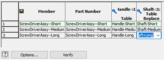
Figure 3.58: iAssembly Member, Part Number, and iPart Table values required
- Select Verify, then OK to complete.
- The iAssembly has now been completed. Note in the Model Browser of the assembly that the iAssembly configuration has appeared. Open the node, as shown in Figure 3.59, and double-click each iAssembly member to update the model. The screwdriver should update to a Short, Medium, or Long version, with both iParts working together. Once saved, this iAssembly can be configured and placed within a new assembly, or independent files can be generated from it.
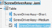
Figure 3.59: Completed iAssembly options that change the assembly configuration
You have successfully created an iAssembly of a screwdriver with three length variations that comprises two iParts. This means that assembly configurations of this product can now be edited, updated, and generated efficiently, as existing data is being copied and reused.
Model credits
The following is the model credit for this chapter:
Steering Wheel Lower Lid (by Furkan Güler): https://grabcad.com/library/steering-wheel-lower-lid-1