In the last chapter, we saw how to get a simple Away3D application up and running by creating a class that added a sphere to the scene. The sphere is just one of many primitive 3D objects that are included with Away3D. This includes some common shapes like cubes, planes, and cones, and some not so common shapes, such as a sea turtle. In this chapter, we will look at a number of classes that can be used to create primitive 3D objects by creating a sample application that adds each of them to the scene in response to input via the keyboard.
But before diving into these primitive classes, we will first learn about the basic elements; vertices, triangle faces, Sprite3D objects, and segments; that are used as the building blocks for more complex 3D shapes. In addition, we will explore the UV coordinate system, which defines how texture maps are applied to the surface of a 3D object.
This chapter covers the following:
- A look at the basic elements that make up a 3D object
- The UV coordinate system
- Creating and displaying the primitive 3D objects included in Away3D
Each 3D object displayed by Away3D is actually a collection of a number of base elements that have been combined to create the shape you see on the screen. There are four base elements that are used to construct more complex 3D objects:
- Vertices
- Triangle faces
- Sprite3D objects
- Segments
While some of these elements cannot be seen directly, they still play a vital role in creating the end result. Let's take a look at these basic elements, and how they work together to create a 3D object.
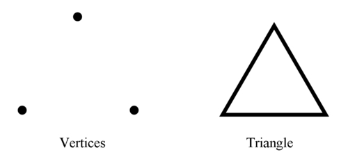
A vertex is a point in 3D space defined by its position along the X, Y, and Z axes. An individual vertex does not have any volume or shape, and is not visible in the scene, but they can be used in combination to represent the corners of 3D shapes.
Vertices are represented by the Vertex class from the away3d.core.base package.
A group of three vertices are used to define the corners of a triangle, otherwise known as a triangle face, or just a face.
The triangle face is one of the three elements used by Away3D that can be added directly to a mesh to create more complex shapes. A mesh can be thought of as a container used to hold a collection of these basic elements, allowing them to be displayed as a group to visualize more recognizable 3D objects. Meshes are represented by the Mesh class from the away3d.core.base package.
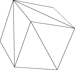
Simple meshes can be made up using a small number of triangle faces. This cube mesh is made up of 12 triangles: 2 triangles for each side.
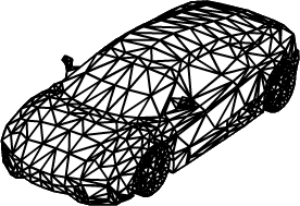
More complex meshes, such as this car, can comprise several thousand triangle faces.
Triangle faces are represented by the Face class from the away3d.core.base package. Here is some example code that creates a mesh containing a single triangle face.
First, we need to create a new instance of the Mesh class. This will hold the triangle face element.
var mesh:Mesh = new Mesh();
Next, we create a new instance of the Face class. This represents the triangle face element that will be added to the mesh.
var face:Face = new Face(
The first three parameters passed to the Face constructor define the three vertices that make up the corners of the triangle.
new Vertex(0, 10, 0),new Vertex(-10, -10, 0),new Vertex(10, -10, 0),
The fourth parameter can be used to define a material that is applied to this element. Chapter 5, Materials, looks at materials in more detail. We have passed in null here, which means the triangle face will use the default mesh material.
Tip
The default material applied to a mesh is an instance of the WireColorMaterial class, which displays a color that is randomly assigned each time a WireColorMaterial object is constructed. This means that the triangle face being created here will display a different color each time the application is run.
null,
The last three parameters define the UV coordinates to be applied to the triangle face, which in turn define how a material will be applied. The following UV coordinates section discusses these coordinates in more detail.
new UV(0, 0),new UV(0, 1),new UV(1, 0));
Finally, the triangle face is added as part of the mesh.
mesh.addFace(face);
The resulting Mesh object can then be added to the scene.
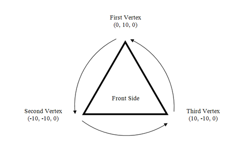
The order in which the vertices are defined in a triangle face determine which side of the triangle is considered the front, and which side is the back. The distinction is important because the back of a triangle face is not visible, by default.
The side whose vertices are arranged in counterclockwise order is the front of the triangle face. The following image shows how the order of the Vertex objects passed in as the first three parameters to the Face constructor, and the counterclockwise direction that they make, define the front and back sides of the triangle face.
This process of creating a triangle face and adding it to a mesh is essentially how most of the primitive shapes included in Away3D are constructed, although some of the primitive classes, such as the Cube class, extend the AbstractPrimitive class from the away3d.primitives package to utilize the number of utility functions that the AbstractPrimitive class provides to aid in the creation of primitive shapes.
Meshes can also contain Sprite3D objects, which are 2D rectangular shapes that are always oriented so they face the camera. While a Sprite3D object has no depth, because it is never viewed from the side, this lack of depth is never perceived by the camera.
The Sprite3D class exists in the away3d.sprites package. Here is an example that creates a Mesh object containing a single Sprite3D object that sits at the meshes origin.
var mesh:Mesh = new Mesh();
The first parameter of the Sprite3D constructor is the material that it will display. It is an optional parameter that defaults to null. Without a material a Sprite3D object simply displays a rectangle. To make this example more interesting we supply a new instance of the BitmapMaterial class, which is set to display an embedded image file called MyEmbeddedTexture. Materials, the Cast class, and embedding resources are covered in more detail in Chapter 5, Materials.
var sprite:Sprite3D = new Sprite3D(
  new BitmapMaterial(Cast.bitmap(MyEmbeddedTexture))
);
The Sprite3D object is then added to its parent mesh using the addSprite() function.
mesh.addSprite(sprite);
Sprite3D objects can be utilized to display details that appear the same from any direction, like snowflakes or ball decorations on a Christmas tree. Sprite3D objects are very simple elements, and therefore fast to render. Using Sprite3D objects in place of a group of triangle faces can lead to significant gains in performance.
Take the mesh representing the Earth in the following figure. This might be a part of an astronomical application designed to show off the solar system, and would be typically created from a sphere primitive. The wireframe image on the left shows the triangle faces that make up the sphere, and the image on the right shows the sphere with a texture of the Earth applied to it.
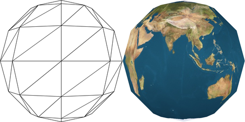
This sphere is built up from a relatively small number of triangle faces, which means that the sphere appears to have a number of sharp, angular edges. Because of the low triangle count, you could expect an Away3D application displaying this one sphere to perform well. But what if you are displaying all the planets? Maybe you also want to display all the moons around all the planets as well. Rendering the triangle faces for all those additional spheres does add up.
Now take a look at a mesh that contains a single Sprite3D object.
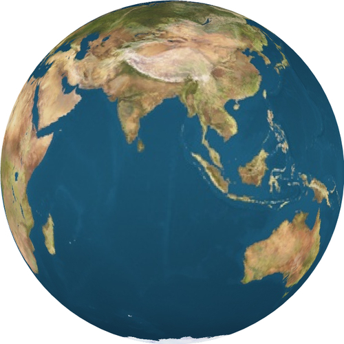
The Sprite3D object is displaying a material that shows the Earth from a single angle. The texture used by this material has been pre-rendered from a sphere made up of many thousands of triangles, which eliminates the sharp edges seen in the previous triangle mesh. Away3D can render this Sprite3D object, displaying the pre-rendered texture, much faster than it can display the lower-quality sphere from the first two images. An application displaying all the planets and moons in the solar system will run at a much higher level or performance if they were displayed as meshes made up of a single Sprite3D object, as opposed to being displayed as meshes made up of a number of triangle faces.
The downside to Sprite3D objects is that, unlike regular 3D objects, they appear the same when viewed from different angles. Even if we were to view the mesh built using a Sprite3D object representing the Earth from the other side, it would still show the Indian Ocean. You can see this effect in action with the CompareSprite3DTriMesh application from the Packt website.
Note
Away3D includes a class called DirectionalSprite that allows different images to be displayed by a flat object as the angle that it is viewed from changes. This class is covered in more detail in Chapter 9, Special Effects with Sprites.
Segments are used to display 2D lines. Strictly speaking, a 2D line has no volume, and should therefore be invisible. However, there are many situations where being able to view a line within the scene is useful.
Segments are represented by the Segment class from the away3d.core.base package. The geometry of a segment is defined between two vertices. Here is an example that creates a Mesh object containing a single Segment object stretching 50 units either side along the X-axis of the meshes origin:
var mesh:Mesh = new Mesh();
var segment:Segment = new Segment(
    new Vertex(-50, 0, 0),
    new Vertex(50, 0, 0)
);
Segments are added to their parent mesh using the addSegment() function.
mesh.addSegment(segment);