
You have probably seen those smart plugs in your local shop: they allow you to not only control appliances remotely, but also to measure the energy consumption of the device connected to the plug. These smart plugs are now available nearly everywhere, from well-known brands such as Belkin.
The following image shows one I bought as an experiment a while ago to see what components were inside:

In this chapter, we are going to learn how to use the Raspberry Pi Zero to make a project that has the same functionalities as a smart plug. You will be able to control an electrical device such as a lamp via Wi-Fi, and also measure its electrical consumption in real time.
Because we are building this device ourselves, we will of course be able to customize it for our needs. For example, we'll learn how to log the data measured by the plug in a database so it can be used later. Let's start!
As always, we are going to start with a list of required hardware and software components for the project.
Except for the Raspberry Pi Zero, you will need some additional components for each of the sections in this chapter.
The most important component will be a current sensor, which we will use to know how much current is flowing through the device. For that, we will use the ECS-1030 non-invasive current sensor. The following is an image of this sensor:

The advantage of this sensor is that you don't need to cut anything to measure the current flowing in the device. To use this sensor, and convert the current it measures to a voltage we can measure, you'll also need a 10-Ohm resistor.
However, we can't directly connect this device to our Raspberry Pi. First, the device has a jack connector at the end, so we need a jack-to-breadboard adapter to connect it first to a breadboard and then to Pi.
Also, we can't connect it to Pi because the Raspberry Pi can only read digital signals. Or, the current sensor is returning an analog signal, which is proportional to the measured current.
To solve this second problem, we'll use a MCP3008 chip, which is an analog-digital converter that can be easily interfaced with the Pi.
To control a device from the Pi, the most important component will be the PowerSwitch Tail Kit. This component allows your Pi to control electrical appliances such as lamps, heaters, and other appliances that use mains electricity to function.
Finally, you will need the usual breadboard and jumper wires.
The following is the list of components you will need for this whole chapter, not including the Raspberry Pi Zero:
- Non-invasive current sensor (https://www.sparkfun.com/products/11005)
- 10-Ohm resistor load
- MCP3008 ADC (https://www.adafruit.com/product/856)
- Jack to breadboard adapter (https://www.sparkfun.com/products/11570)
- PowerSwitch Tail Kit (https://www.adafruit.com/products/268)
- Breadboard (https://www.adafruit.com/products/64)
- Jumper wires (https://www.adafruit.com/products/1957)
To actually have a device to control, I used a standard 15W desk lamp.
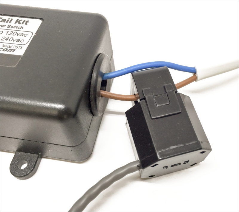
We are now going to assemble the hardware for this project. The first thing we have to do is to connect the current sensor to the PowerSwitch Tail so we can measure the current flowing into the device connected to the smart plug. For that, you'll need to expose a bare cable coming from the PowerSwitch Tail. Then, open the current sensor and close it firmly around this cable.
The following image shows how the connection should look:
Now, we are going to connect the MCP3008 to the Raspberry Pi. To help you out, the following figure shows the connector of the Raspberry Pi Zero with the numbers of the GPIO pins:

Also, you will need to know the pins of the MCP3008 chip:

Let's now connect the MCP3008 to the Raspberry Pi, using the following connections:
- VDD and VREF to the 3.3V pin of the Raspberry Pi
- DGND and AGND to the GND pin of the Raspberry Pi
- CLK to GPIO 11 of the Raspberry Pi
- DOUT to GPIO 9 of the Raspberry Pi
- DIN to GPIO 10 of the Raspberry Pi
- CS to GPIO 8 of the Raspberry Pi
After that, plug the current sensor into the Jack adapter and place the adapter on the breadboard. Then, connect the 10-Ohm resistor in series with the SLEEVE and TIP pins on the adapter.
Now, connect one side of this resistor to the GND on the breadboard (for example, to the Raspberry Pi GND) and the other side to channel 5 of the MCP3008 chip.
Finally, connect the PowerSwitch Tail to the Pi: connect the Vin+ pin to GPIO 18 and the two other pins to the GND.
The following image shows the final result:

Also, connect the device you want to control, for example, a lamp, to the female plug of the PowerSwitch. You can now again plug your Pi into the power source and the PowerSwitch Tail to the mains electricity.