
Chapter 28. SDN and Network Programmability
This chapter covers the following exam topics:
4.0 Infrastructure Services
4.5 Verify ACLs using the APIC-EM Path Trace ACL analysis tool
5.0 Infrastructure Maintenance
5.5 Describe network programmability in enterprise network architecture
5.5.a Function of a controller
5.5.b Separation of control plane and data plane
5.5.c Northbound and southbound APIs
Welcome to the final technology-focused chapter of the book!
The broad topic area called network programmability by some, or Software Defined Networking by others, creates a new way to build networks.
The CCNA R&S certification teaches the traditional model for operating and controlling networks, a model that has existed for decades. You understand protocols that the devices use, understand the commands that can customize how those protocols operate, and add distributed configuration to the devices, device by device, to implement the network.
Network programmability changes the operational model for networks, requiring new methods of controlling the devices to enable the new operational models. The term network programmability itself refers to more focus on software control of the network, so that the network can be changed more easily to adapt to the ever-changing environment as virtual machines (VM) move in a data center, and traffic patterns change, and so forth. The similar term Software Defined Networking (SDN), used frequently in the trade press, also emphasizes the concept of software (programmatic) control of the network, rather than the more static configuration-controlled networking.
As with the previous chapter covering cloud computing, this chapter can only begin to introduce the concepts of network programmability and SDN, because the topic is simply too large. Thankfully, the related exam topics focus on the most fundamental ideas of SDN. The first major section of this chapter introduces the basic concepts mentioned in the exam topics, specifically the data and control planes, along with controllers and the related architecture. The second section then shows three separate product examples of network programmability, all of which use different methods to implement networking features. The last section focuses on one additional feature of the APIC-EM product.
“Do I Know This Already?” Quiz
Take the quiz (either here, or use the PCPT software) if you want to use the score to help you decide how much time to spend on this chapter. The answers are at the bottom of the page following the quiz, and the explanations are in DVD Appendix C and in the PCPT software.

1. A Layer 2 switch examines a frame’s destination MAC address and chooses to forward that frame out port G0/1 only. That action is an action that occurs as part of which plane of the switch?
a. Data plane
b. Management plane
c. Control plane
d. Table plane
2. A router uses EIGRP to learn routes and adds those to the IPv4 routing table. That action is an action that occurs as part of which plane of the switch?
a. Data plane
b. Management plane
c. Control plane
d. Table plane
3. A network uses an SDN architecture with switches and a centralized controller. Which of the following terms describes a function or functions expected to be found on the switches but not on the controller?
a. A Northbound Interface
b. A Southbound Interface
c. Data plane functions
d. Control plane functions
4. Which of the following controllers (if any) from Cisco uses a mostly centralized control plane model?
a. Cisco Open SDN Controller
b. Cisco Application Policy Infrastructure Controller (APIC)
c. Cisco APIC Enterprise Module (APIC-EM)
d. None of these controllers uses a mostly centralized control plane.
5. Host A and Host B sit in two different subnets. The path between the subnets of these two hosts runs through three different Layer 3 forwarding devices (routers and Layer 3 switches). A network engineer uses the APIC-EM Path Trace ACL Analysis tool to analyze the path used for Host A to send packets to Host B. Which part of the function is done specifically by the ACL Analysis or ACL Trace part of the tool?
a. Discovery of the topology that exists between the two hosts
b. Analysis of the Layer 3 forwarding decisions in the path from Host A to B
c. Analysis of the Layer 2 forwarding decisions in the path from Host A to B
d. Analysis of the impact of ACLs on the packets that would flow from Host A to B
Answers to the “Do I Know This Already?” quiz:
Foundation Topics
SDN and Network Programmability Basics
Networking devices forward data in the form of messages, typically data link frames like Ethernet frames. You have learned about how switches and routers do that forwarding for the entire length of preparing for the CCNA R&S exam.
Network programmability and SDN takes those ideas, analyzes the pieces, finds ways to improve them for today’s needs, and reassembles those ideas into a new way of making networks work. At the end of that rearrangement, the devices in the network still forward messages, but the how and why has changed.
This first major section explains the most central concepts of SDN and network programmability. It starts by breaking down some of the components of what exists in traditional networking devices. Then this section explains how some centralized controller software, called a controller, creates an architecture for easier programmatic control of a network.
The Data, Control, and Management Planes
Stop and think about what networking devices do. What does a router do? What does a switch do?
Many ideas should come to mind. For instance, they physically connect to each other with cables, and with wireless, to create networks. They forward messages: switches forward Ethernet frames, and routers forward packets. They use many different protocols to learn useful information, like routing protocols for learning network layer routes.
Everything that networking devices do can be categorized as being in a particular plane. This section takes those familiar facts about how networking devices work, and describes the three planes most often used to describe how network programmability works: the data plane, the control plane, and the management plane.
The Data Plane
The term data plane refers to the tasks that a networking device does to forward a message. In other words, anything to do with receiving data, processing it, and forwarding that same data—whether you call the data a frame, packet, or, more generically, a message—is part of the data plane.
For example, think about how routers forward IP packets, as shown in Figure 28-1. If you focus on the Layer 3 logic for a moment, the host sends the packet (Step 1) to its default router, R1. R1 does some processing on the received packet, makes a forwarding (routing) decision, and forwards the packet (Step 2). Routers R3 and R4 also receive, process, and forward the packet (Steps 3 and 4).

Now broaden your thinking for a moment, and try to think of everything a router or switch might do when receiving, processing, and forwarding a message. Of course, the forwarding decision is part of the logic; in fact, the data plane is often called the forwarding plane. But think beyond matching the destination address to a table. For perspective, the following list details some of the more common actions that a networking device does that fit into the data plane:

![]() De-encapsulating and re-encapsulating a packet in a data link frame (routers, Layer 3 switches)
De-encapsulating and re-encapsulating a packet in a data link frame (routers, Layer 3 switches)
![]() Adding or removing an 802.1Q trunking header (routers and switches)
Adding or removing an 802.1Q trunking header (routers and switches)
![]() Matching the destination MAC address to the MAC address table (Layer 2 switches)
Matching the destination MAC address to the MAC address table (Layer 2 switches)
![]() Matching the destination IP address to the IP routing table (routers, Layer 3 switches)
Matching the destination IP address to the IP routing table (routers, Layer 3 switches)
![]() Encrypting the data and adding a new IP header (for VPN processing)
Encrypting the data and adding a new IP header (for VPN processing)
![]() Changing the source or destination IP address (for NAT processing)
Changing the source or destination IP address (for NAT processing)
![]() Discarding a message due to a filter (ACLs, port security)
Discarding a message due to a filter (ACLs, port security)
All the items in the list make up the data plane, because the data plane includes all actions done per message.
The Control Plane
Next, take a moment to ponder the kinds of information that the data plane needs to know beforehand so that it can work properly. For instance, routers need IP routes in a routing table before the data plane can forward packets. Layer 2 switches need entries in a MAC address table before they can forward Ethernet frames out the one best port to reach the destination. Switches must use Spanning Tree Protocol (STP) to limit which interfaces can be used for forwarding so that the data plane works well and does not loop frames forever.
From one perspective, the information supplied to the data plane controls what the data plane does. For instance, a router with no routes in the routing table cannot forward packets. The data plane is there, but when a router’s data plane tries to match the routing table, and finds no matching route, the router discards the packet. However, once the router has some routes, the router’s data plane processes can forward packets. And what controls the contents of the routing table? Various control plane processes.
The term control plane refers to any action that controls the data plane. Most of these actions have to do with creating the tables used by the data plane, tables like the IP routing table, an IP ARP table, a switch MAC address table, and so on. By adding, removing, and changing entries to the tables used by the data plane, the control plane processes control what the data plane does. You already know many control plane protocols, of course, including all IP routing protocols.
Traditional networking protocols and devices separate the control and data planes and distribute those functions into each individual device, as shown in the example in Figure 28-2. In this case, OSPF, the control plane protocol, runs on each router (that is, it is distributed among all the routers). OSPF on each router then adds to, removes from, and changes the IP routing table on each router. Once populated with useful routes, the data plane of the routers, also distributed to each router, can forward incoming packets, as shown from left to right across the bottom of the figure.

The following list includes many of the more common control plane protocols:
![]() Routing protocols (OSPF, EIGRP, RIP, BGP)
Routing protocols (OSPF, EIGRP, RIP, BGP)
![]() IPv4 ARP
IPv4 ARP
![]() IPv6 NDP
IPv6 NDP
![]() Switch MAC learning
Switch MAC learning
![]() STP
STP
Without the protocols and activities of the control plane, the data plane of traditional networking devices would not function well. Routers would be mostly useless without routes learned by a routing protocol. Without learning MAC table entries, a switch could still forward unicasts by flooding them, but doing that for all frames would create much more load on the LAN compared to normal switch operations. So the data plane must rely on the control plane to provide useful information.
The Management Plane
The control plane does overhead tasks that directly impact the behavior of the data plane. The management plane does overhead work as well, but that work does not directly impact the data plane. Instead, the management plane includes protocols that allow network engineers to manage the devices.
Telnet and SSH are two of the most obvious management plane protocols. To emphasize the difference with control plane protocols, think about two routers: one configured to allow Telnet and SSH into the router, and one that does not. Both could still be running a routing protocol and routing packets, whether or not they support Telnet and SSH.
Figure 28-3 lists some of the more common management plane protocols from the CCNA R&S exam.

Cisco Switch Data Plane Internals
To better understand SDN and network programmability, it helps to think about the internals of switches. This next topic does just that.
From the very first days of devices called LAN switches, switches had to use specialized hardware to forward frames, because of the large number of frames per second (fps) required. To get a sense for the volume of frames a switch much be able to forward, consider the minimum frame size of an Ethernet frame, the number of ports on a switch, and the speeds of the ports; even low-end switches need to be able to forward millions of frames per second. For example, if a switch manufacturer wanted to figure out how fast their data plane needed to be in a new access layer switch with 24 ports, they might work through this bit of math:
![]() The switch has 24 ports.
The switch has 24 ports.
![]() Each port runs at 100 Mbps each.
Each port runs at 100 Mbps each.
![]() For this analysis, assume frames 125 bytes in length (to make the math easier, because each frame is 1000 bits long).
For this analysis, assume frames 125 bytes in length (to make the math easier, because each frame is 1000 bits long).
![]() Use full duplex on all ports, so the switch can expect to receive on all 24 ports at the same time.
Use full duplex on all ports, so the switch can expect to receive on all 24 ports at the same time.
![]() Result: Each port would be receiving 100,000 fps, for 2.4 million fps total, so the switch data plane would need to be ready to process 2.4 million fps.
Result: Each port would be receiving 100,000 fps, for 2.4 million fps total, so the switch data plane would need to be ready to process 2.4 million fps.
While 2.4 million fps may seem like a lot, the goal here is not to put an absolute number on how fast the data plane of a switch needs to be for any given era of switching technology. Instead, from their first introduction into the marketplace in the mid-1990s, LAN switches needed a faster data plane than a generalized CPU could process in software. As a result, hardware switches have always had specialized hardware to perform data plane processing.
First, the switching logic occurs not in the CPU with software, but in an application-specific integrated circuit (ASIC). An ASIC is a chip built for specific purposes, such as for message processing in a networking device.
Second, the ASIC needs to perform table lookup in the MAC address table, so for fast table lookup, the switch uses a specialized type of memory to store the equivalent of the MAC address table: ternary content-addressable memory (TCAM). TCAM memory does not require the ASIC to search the table. Instead, the ASIC can feed the fields to be matched, like a MAC address value, into the TCAM, and the TCAM returns the matching table entry, without a need to run a search algorithm.
Note that a switch still has a general-purpose CPU and RAM as well, as shown in Figure 28-4. IOS runs in the CPU and uses RAM. Most of the control and management plane functions run in IOS. The data plane function (and the control plane function of MAC learning) happens in the ASIC.

Note that some routers also use hardware for data plane functions, for the same kinds of reasons that switches use hardware. (For instance, check out the Cisco Quantum Flow Processor for interesting reading about hardware data plane forwarding in Cisco routers.) The ideas of a hardware data plane in routers are similar to those in switches: use a purpose-built ASIC for the forwarding logic, and TCAM to store the required tables for fast table lookup.
Controllers and Network Architecture
New approaches to networking have emerged in the 2010s, approaches that change where some of the control plane functions occur. Many of those approaches move parts of the control plane work into software that runs as a centralized application called a controller. This next topic looks at controller concepts, and the interfaces to the devices that sit below the controller and to any programs that use the controller.
Controllers and Centralized Control
Most traditional control plane processes use a distributed architecture. That is, the control plane is distributed, running on many devices. For example, each router runs its own OSPF routing protocol process. To do their work, those distributed control plane processes use messages to communicate with each other, like OSPF protocol messages between routers. As a result, traditional networks are said to use a distributed control plane.
The people who created today’s control plane concepts, like STP, OSPF, EIGRP, and so on, could have chosen to use a centralized control plane. That is, they could have put the logic in one place, running on one device, or on a server. Then the centralized software could have used protocol messages to learn information from the devices, but with all the processing of the information at a centralized location. But they instead chose a distributed architecture.
There are pros and cons to using distributed and centralized architectures to do any function in a network. Many control plane functions have a long history of working well with a distributed architecture. However, a centralized application can be easier to write than a distributed application, because the centralized application has all the data gathered into one place. And this emerging world of network programmability and SDN often uses a centralized architecture, with a centralized control plane, with its foundations in a service called a controller.
A controller, or SDN controller, centralizes the control of the networking devices. The degree to which control is centralized can vary, from the controller performing all control plane functions, to the other end of the spectrum, in which the controller is simply aware of the ongoing work of the distributed control plane.
To better understand the idea of a controller, consider the case shown in Figure 28-5, in which one SDN controller centralizes all important control plane functions. First, the controller sits anywhere in the network that has IP reachability to the devices in the network. Each of the network devices still has a data plane. However, note that none of the devices has a control plane. In the variation of SDN as shown in Figure 28-5, the controller (or a program making use of the controller) directly programs the data plane entries into each device’s tables. The networking devices do not populate their forwarding tables with traditional distributed control plane processes.
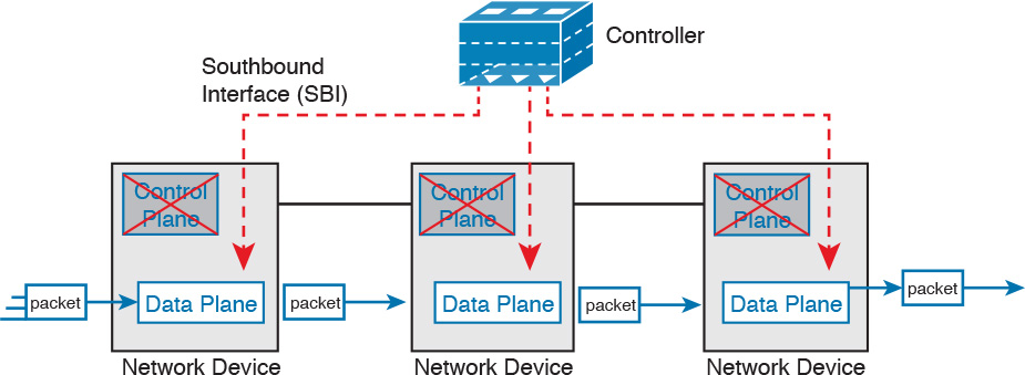
Figure 28-5 shows one model for network programmability and SDN, but not all. The figure does give us a great backdrop to discuss a few more important basic concepts, in particular, the idea of a Southbound Interface (SBI) and Northbound Interface (NBI).
The Southbound Interface
In a controller-based network architecture, the controller needs to communicate to the networking devices. In most network drawings and architecture drawings, those network devices typically sit below the controller, as shown in Figure 28-5. There is an interface between the controller and those devices, and given its location in drawings, the interface came to be known as the Southbound Interface, or SBI, as labeled in Figure 28-5.
The word “interface” is used throughout this book to refer to physical connectors on routers and switches. However, in the context of this chapter’s discussion of SDN, the word “interface” (including in the names of SBI, NBI, and API) refers to software interfaces unless otherwise noted.
Several different options exist for the SBI. The overall goal is network programmability, so the interface moves away from being only a protocol. An SBI often includes a protocol, so that the controller and devices can communicate, but they often include an application programming interface, or API.
An API is a method for one application (program) to exchange data with another application. Rearranging the words to describe the idea, an API is an interface to an application program. Programs process data, so an API lets two programs exchange data. While a protocol exists as a document, often from a standards body, an API often exists as usable code—functions, variables, and data structures—that can be used by one program to communicate and copy structured data between the programs across a network.
So, back to the term SBI: It is an interface between a program (the controller) and a program (on the networking device) that lets the two programs communicate, with one goal being to allow the controller to program the data plane forwarding tables of the networking device.
Unsurprisingly, in a network architecture meant to enable network programmability, the capabilities of the SBIs and their APIs tell us a lot about what that particular architecture can and cannot do. For instance, some controllers may support one or a few SBIs, for a specific purpose, while others may support many more SBIs, allowing choice of SBIs to use. The comparisons of SBIs go far beyond this chapter, but it does help to think about a few; the second major section gives three example architectures that happen to show three separate SBIs, specifically:
![]() OpenFlow (from the ONF; https://www.opennetworking.org)
OpenFlow (from the ONF; https://www.opennetworking.org)
![]() OpFlex (from Cisco; used with ACI)
OpFlex (from Cisco; used with ACI)
![]() CLI (Telnet/SSH) and SNMP (from Cisco; used with APIC-EM)
CLI (Telnet/SSH) and SNMP (from Cisco; used with APIC-EM)
The Northbound Interface
Think about the programming required at the controller related to the example in Figure 28-5. The figure focuses on the fact that the controller can add entries to the networking device’s forwarding tables. However, how does the controller know what to add? How does it choose? What kind of information would your program need to gather before it could attempt to add something like MAC table entries or IP routes to a network? You might think of these:
![]() A list of all the devices in the network
A list of all the devices in the network
![]() The capabilities of each devices
The capabilities of each devices
![]() The interfaces/ports on each device
The interfaces/ports on each device
![]() The current state of each port
The current state of each port
![]() The topology: which devices connect to which, over which interfaces
The topology: which devices connect to which, over which interfaces
![]() Device configuration: IP addresses, VLANs, and so on as configured on the devices
Device configuration: IP addresses, VLANs, and so on as configured on the devices
A controller does much of the work needed for the control plane in a centralized control model. It gathers all sorts of useful information about the network, like the items in the previous list. The controller itself can create a centralized repository of all this useful information about the network.
A controller’s Northbound Interface (NBI) opens the controller so its data and functions can be used by other programs, enabling network programmability, with much quicker development. Programs can pull information from the controller, using the controller’s APIs. The NBIs also enable programs to use the controller’s abilities to program flows into the devices using the controller’s SBIs.
To see where the NBI resides, first think about the controller itself. The controller is software, running on some server, which can be a VM or a physical server. An application can run on the same server as the controller, and use an NBI, which is an API, so that two programs can communicate.
Figure 28-6 shows just such an example. The big box in the figure represents the system where the controller software resides. This particular controller happens to be written in Java, and has a Java-based native API. Anyone—the same vendor as the controller vendor, another company, or even you—can write an app that runs on this same operating system that uses the controller’s Java API. By using that API to exchange data with the controller, the application can learn information about the network. The application can also program flows in the network—that is, ask the controller to add the specific match/action logic (flows) into the forwarding tables of the networking devices.

Note
The Northbound Interface (NBI) gets its name from its normal location as shown above the controller; that is, in what would be north on a map.
Before leaving the topic of NBIs, let me close with a brief explanation of a REST API as used for a controller. REST (Representational State Transfer) describes a type of API that allows applications to sit on different hosts, using HTTP messages to transfer data over the API. When you see SDN figures like Figure 28-6, with the application running on the same system as the controller, the API does not need to send messages over a network, because both programs run on the same system. But when the application runs on a different system somewhere else in the network other than running on the controller, the API needs a way to send the data back and forth over an IP network, and RESTful APIs meet that need.
Figure 28-7 shows the big ideas with a REST API. The application runs on a host at the top of the figure. In this case, at Step 1, it sends an HTTP GET request to a particular URI. The HTTP GET is like any other HTTP GET, even like those used to retrieve web pages. However, the URI is not for a web page, but rather identifies an object on the controller, typically a data structure that the application needs to learn and then process. For example, the URI might identify an object that is the list of physical interfaces on a specific device along with the status of each.

At Step 2, the controller sends back an HTTP GET response message with the object. Most REST APIs will ask for and receive structured data. That is, instead of receiving data that is a web page, like a web browser would receive, the response holds variable names and their values, in a format that can be easily used by a program. The common formats for data used for network programmability are JSON (JavaScript Object Notation) and XML (eXtensible Markup Language), shown as Step 3.
SDN Architecture Summary
SDN and network programmability introduce a new way to build networks. The networking devices still exist, and still forward data, but the control plane functions and location can change dramatically. The centralized controller acts as the focal point, so that at least some of the control plane functions move from a distributed model to a centralized model.
However, the world of network programmability and SDN includes a wide array of options and solutions. Some options pull most control plane functions into the controller, while others pull only some of those functions into the controller. The next section takes a look at three different options, each of which takes a different approach to network programmability and the degree of centralized control.
Examples of Network Programmability and SDN
This second of three major sections of the chapter introduces three different SDN and network programmability solutions available from Cisco. Others exist as well. These three were chosen because they give a wide range of comparison points:
![]() Open SDN Controller and OpenFlow
Open SDN Controller and OpenFlow
![]() Cisco Application Centric Infrastructure (ACI) and OpFlex
Cisco Application Centric Infrastructure (ACI) and OpFlex
![]() Cisco APIC Enterprise Module (APIC-EM)
Cisco APIC Enterprise Module (APIC-EM)
Open SDN and OpenFlow
One common form of SDN comes from the Open Networking Foundation, and is billed as Open SDN. The ONF (https://www.opennetworking.org) acts as a consortium of users and vendors to help establish SDN in the marketplace. Part of that work defines protocols, SBIs, NBIs, and anything that helps people implement their vision of SDN.
The ONF model of SDN features OpenFlow as the SBI. Part of OpenFlow defines an IP-based protocol used between the controller and the network devices. Just as important, OpenFlow defines a standard idea of what a switch’s capabilities are, based on the ASICs and TCAMs commonly used in switches today. (That standardized idea of what a switch does is called a switch abstraction.) An OpenFlow switch can act as a Layer 2 switch, a Layer 3 switch, or in different ways and with great flexibility beyond the traditional model of a Layer 2/3 switch.
The Open SDN model centralizes most control plane functions, with control of the network done by the controller plus any applications that use the controller’s NBIs. In fact, earlier Figure 28-5, which showed the network devices without a control plane, was meant to represent this mostly centralized ONF model of SDN. The applications may use any APIs (NBIs) supported on the controller platform. However, it calls for OpenFlow as the SBI protocol. Additionally, the networking devices need to be switches that support OpenFlow.
Because the ONF’s Open SDN model has this common thread of a controller with an OpenFlow SBI, the controller plays a big role in the network. The next few pages provide a brief background about two such controllers.
The OpenDaylight Controller
First, if you were to look back at the history of OpenFlow, a wide variety of SDN controllers have been written. Some were more research oriented, while SDN was being developed and was more of an experimental idea. As time passed, more and more vendors began building their own controllers. And those controllers often had many similar features, because they were trying to accomplish many of the same goals.
Some companies got together to attempt to create an open source SDN controller, with many of the same principles of how Linux has been developed over the years. Part of the idea was that if enough vendors worked together on a common open source controller, then all would benefit. All those vendors could then use the open source controller as the basis for their own products, with each vendor focusing on the product differentiation part of the effort, rather than the fundamental features. The result was that back in the mid-2010s, the OpenDaylight SDN controller (https://www.opendaylight.org) was born.
The OpenDaylight (ODL) project exists as a project of the Linux Foundation. If that fact was not enough to convince you it is legit, OpenDaylight has backing from many vendors, including Cisco. Many of the corporate participants contribute significant money and people annually.
Figure 28-8 shows a generalized version of the ODL architecture. In particular, note the variety of SBIs listed in the lower part of the controller box: OpenFlow, NetConf, PCEP, BGP-LS, and OVSDB; many more exist. The ODL project has enough participants so that it includes a large variety of options, including multiple SBIs, not just OpenFlow.

ODL has many features, with many SBIs, and many core features. A vendor can then take ODL, use the parts that make sense for that vendor, add to it, and create a commercial ODL controller. Just a brief look around the OpenDaylight.org website when writing this chapter in early 2016 showed a listing of 15 commercial SDN controllers based on ODL, including the Cisco Open SDN Controller, described next.
Cisco Open SDN Controller
Cisco has a wide product line, with a large number of products, many of which support network programmability and SDN. One such product, the Cisco Open SDN Controller (OSC), acts as an SDN controller, and is Cisco’s commercial version of ODL. Cisco follows the intended model for the ODL project: Cisco and others contribute labor and money to the ODL open source project; once a new release is completed, Cisco takes that release and builds new versions of their product. ODL licensing allows any vendor to take the open source code and package it with additional code and support.
The idea of having a free open source product, and a similar commercial product, is not a new concept in the open source world. In fact, the Linux OS follows that same model: You can download Linux for free to run on your own computer, but companies that use Linux in production may (and often do) want to run a supported and stable commercial version with support available.
Comparing the two controllers—that is, ODL and OSC—ODL has a longer list of features, but that is the normal progression of how a vendor would create its own offering. ODL includes many features based on the interests and goals of many participating companies. Each vendor picks the subset it wants to use, test, and support for its own commercial products.
Note that Cisco does support the OpenFlow and ONF model of OpenFlow through OSC and a small part of the Cisco router and switch product line. Cisco customers today (at least at publication) can purchase OSC, and some models of Cisco Nexus switches, plus some Cisco ASR series routers, with the routers and switches supporting OpenFlow. However, Cisco does not appear to be setting about to migrate its entire product line to support OpenFlow, instead taking a different approach to implementing SDN for different parts of a network and for different goals. The next two topics show two such offerings.
The Cisco Application Centric Infrastructure
The ONF Open SDN model with OpenFlow gives the centralized software great power and flexibility by enabling direct programming of the data plane forwarding tables on the devices. However, the end goal of that architecture is about enabling software control of the network and how it operates, so that software can automate and change the network based on current conditions in the network. The SDN movement that became OpenFlow meets those goals in particular ways. But SDN with OpenFlow is just one way to enable network programmability and automation.
Cisco looked at the same set of problems and goals for a modern IT infrastructure, the same issues that drove the development of OpenFlow, and reached some different conclusions about how to go about providing network programmability. One of those solutions focused on the data center, where applications run. So, instead of thinking about the network first, the solution began with applications, and what they need, and then built networking concepts around application architectures. Cisco made the network infrastructure become application centric, hence the name of the Cisco data center SDN solution: Application Centric Infrastructure, or ACI.
For example, Cisco looked at the data center world and saw lots of automation and control. As discussed in Chapter 27, virtualization software routinely starts, moves, and stops VMs, and cloud software enables self-service highly elastic services. From a networking perspective, some of those VMs need to communicate, but some do not. And those VMs can move based on the needs of the virtualization and cloud systems, so the idea of having a lot of per-physical-interface configuration on switches and routers was just a poor model.
The model that Cisco defines for ACI uses a concept of endpoints and policies. The endpoints are the VMs (or even traditional servers with the OS running directly on the hardware). Because several endpoints have the same needs, you group them together into aptly named endpoint groups. Then policies can be defined about which endpoint groups can communicate with whom—for instance, a group of web servers may need to communicate with a group of application servers. The policy also defines other key parameters, like which endpoint groups can access each other (or not), as well as QoS parameters and other services.
Note that at no point did the previous paragraph talk about which physical switch interfaces should be assigned to which VLAN, or which ports are in an EtherChannel—the discussion moves to an application-centric view of what happens in the network. Once all the endpoints, policies, and related details are defined, the controller can then direct the network as to what needs to be in the forwarding tables to make it all happen—and to more easily react when the VMs start, stop, or move.
To make it all work, ACI uses a centralized controller called the Application Policy Infrastructure Controller (APIC), as shown in Figure 28-9. The name defines the function in this case: It is the controller that creates application policies for the data center infrastructure. The APIC, of course, has a convenient GUI, but the power comes in software control—that is, network programmability. The same virtualization software, or cloud or automation software, even scripts written by the network engineer, can define the endpoint groups, policies, and so on to the APIC. But all these players access the ACI system by interfacing to the APIC; the network engineer no longer needs to connect to each individual switch and configure CLI commands.

ACI uses a partially centralized control plane, RESTful and native APIs, and OpFlex as an SBI. The NBIs allow software control from outside the controller. The controller communicates with the switches connected to the endpoints, and asks those switches to then create the correct flows to be added to the switches. Interestingly, ACI uses a partially distributed control plane, with the controller informing the switches about the desired policies to apply to each endpoint. The switches still have some control plane software that interprets those policies to then add the correct flows to the switch’s own forwarding table.
For more information on Cisco ACI, go to http://www.cisco.com/go/aci.
The Cisco APIC Enterprise Module
The first two solutions discussed in this section move significant parts of the control plane functions into the controller, and require switches that support that model. The ONF’s Open SDN model centralizes most of the control plane, with switches that support OpenFlow. The Cisco ACI solution centralizes much but not all of the control plane, leaving some of the control plane in the switches. However, those switches were newer models of switches with software that supports ACI. Neither the Open SDN model nor the Cisco ACI model uses switches and routers that act like the traditional switch and router discussed throughout this book and the ICND1 book.
The third example of a Cisco SDN solution in this section, called APIC Enterprise Module (APIC-EM), keeps the same traditional switches and routers as discussed throughout this book and the ICND1 Cert Guide. Cisco rejected the idea that its enterprise-wide SDN (network programmability) solution could begin with the assumption of replacing all hardware. Instead, Cisco looked for ways to add the benefits of network programmability while keeping the same traditional switches and routers in place. That approach could certainly change over time, but with its initial introduction into the market in late 2015, the Cisco APIC-EM does just that: offer enterprise SDN using the same switches and routers already installed in networks.
Note
Even though APIC-EM uses the same APIC acronym used for the controller with the Cisco ACI offering, the details of how it works differ significantly.
Per the Cisco product pages, APIC-EM is the Cisco SDN offering for the enterprise. To help with network programmability, the solution uses a centralized controller. At the same time, it attempts to support much of the more recent generations of Cisco enterprise routers and switches by using SBIs that should sound familiar. Summarizing some of the key points:
![]() The solution uses the APIC-EM controller.
The solution uses the APIC-EM controller.
![]() Cisco supplies a variety of applications that reside on the controller, some of which use information gathered by the controller, and some of which control the operation of the network devices.
Cisco supplies a variety of applications that reside on the controller, some of which use information gathered by the controller, and some of which control the operation of the network devices.
![]() The controller has a RESTful Northbound API that can make available that collected information about the entire network over an easy-to-use API.
The controller has a RESTful Northbound API that can make available that collected information about the entire network over an easy-to-use API.
![]() The control and data planes of the network devices remain unchanged, as part of the effort to support existing devices.
The control and data planes of the network devices remain unchanged, as part of the effort to support existing devices.
![]() The SBI uses familiar protocols: Telnet, SSH, and SNMP.
The SBI uses familiar protocols: Telnet, SSH, and SNMP.
Figure 28-10 shows a general view of the APIC-EM controller architecture, with a few of the APIC-EM apps, the REST API, and a list of the SBIs.

The fact that the data plane and control plane do not change needs more explanation. First, APIC-EM will likely change over time; the Cisco product pages even tell us that support for more SBIs will happen. But as it existed in early 2016 (when this chapter was finalized), when using APIC-EM, all the routers and switches still use their data and control planes in the same way, with no changes. The APIC-EM controller does not program flows into tables, nor ask the control plane in the devices to change how it operates. The switches and routers do not need to be ready to change how they operate internally. So, you might wonder, what does the APIC-EM controller do?
First, APIC-EM enables easier network automation for customers. To do that, APIC-EM gathers information about the network over the SBI. That information includes topology, devices, interfaces, operational status, and configuration. Next, APIC-EM makes that information available through extensive NBI APIs. Additionally, APIC-EM makes the data about devices consistent to a great extent, even if the devices use different operating systems.
Second, APIC-EM can still change how the devices operate by changing the configuration of the devices. The SBIs listed in Figure 28-10 include CLI, meaning that APIC-EM can use Telnet and SSH to log in to a device, use the CLI, and issue commands—including to reconfigure the device. With SNMP as the SBI, APIC-EM can also configure the network device with SNMP Set commands.
So in its first version, APIC-EM enables programmability with a centralized controller model, without changing the data and control plane concepts and configuration described throughout this book.
Comparing the Three Examples
The three example SDN branches in this section of the book were chosen to provide a wide variety for the sake of learning. For instance, with Cisco OSC (using OpenFlow) and with Cisco ACI, the network engineer now works with the controller rather than individual devices. However, they differ to some degree in how much of the control plane work is centralized. Table 28-2 lists those and other comparison points taken from this section, for easy review and study.

Also, before leaving these topics, let me offer a few words about learning more about SDN. Cisco DevNet (https://developer.cisco.com), a site for anyone interested in network programming, has information about all the Cisco SDN solutions in this section. It also has free labs as well. You should definitely set up a free login at Cisco DevNet and check out the content there. Also, I blog about SDN from time to time at one of my blog sites (http://www.sdnskills.com); look there for posts with recommendations about what to study to learn about SDN.
Cisco APIC-EM Path Trace ACL Analysis Application
This final section of the chapter was designed to discuss a single exam topic, and only that exam topic, due to some timing challenges. This short section introduces the topic, with a promise of more information to be posted as a PDF on this book’s companion website. Now that I have made you curious, this section first introduces the Path Trace app, then explains more about the ACL Analysis app and the reason why the details are in a free PDF on the website.
APIC-EM Path Trace App
Think of the APIC-EM controller as a set of base features plus a series of applications or apps. The list of supported applications will grow over time. The apps run natively on the controller; that is, they do not run elsewhere in the network but are installed as part of the controller. From a user interface perspective, they appear as just another feature in the user interface, but architecturally, the apps are separate from the base controller, and may even be developed by different groups within Cisco.
APIC-EM supports a variety of apps, and that list will almost certainly expand over time. Currently, when you download the APIC-EM software, the software includes all the apps built in. All the apps can run. As for licensing, some apps, called basic apps, do not require a license—they are free to use (just like APIC-EM itself). Other apps, called solution apps, require the purchase of a license for legal use of the app.
The APIC-EM Path Trace app has been available since version 1.0 of APIC-EM. The idea is simple, but it is a very powerful and useful tool. This tool predicts what happens in the data plane of the various devices in the network. The process works something like this:
1. Before using Path Trace, another APIC-EM app called Discovery discovers the network topology.
2. From the Path Trace part of the GUI, the user can type in a source and destination address of a packet.
3. The Path Trace app examines information pulled by APIC-EM from the devices in the network—the MAC tables, IP routing tables, and other forwarding details in the devices—to analyze where this imaginary packet would flow if sent in the network right now.
4. The Path Trace GUI displays the path, with notes, overlaid on a map of the network.
You and I could do the same work, but it would be laborious. APIC-EM’s Path Trace app does the work with just a few clicks at the user interface.
APIC-EM Path Trace ACL Analysis Tool Timing and Exam Topic
The one exam topic that mentions an APIC-EM app uses a longish phrase: “APIC-EM Path Trace ACL Analysis tool.” This phrase refers to a newer app (not available in version 1.0 or 1.1 of APIC-EM) that takes the work done by Path Trace a step further.
The ACL Analysis tool app depends on the Path Trace app, but it then extends the function of the Path Trace app. Path Trace by itself does not consider ACLs in its analysis of the forwarding path. That is, Path Trace shows where the packet would be forwarded based on MAC address tables and IP routing tables, while ignoring whether an ACL might discard the packet. The ACL Analysis app then examines the chosen path as determined by the Path Trace tool (hence the dependency), but it looks for any enabled ACLs. The ACL Analysis tool analyzes and then characterizes (with notes overlaid on the screen) what packets sent from source to destination would be filtered as it travelled along that path.
Unfortunately for our publishing process, the APIC-EM ACL Path Trace ACL Analysis tool creates a small challenge. The app was not available before we needed to send the book out for its first printing. However, the exam topic refers to that specific feature. The timing for the Cisco release of that feature into the APIC-EM product feature happened to be just a little too late for us to use the final version of the released software when writing this section.
While the timing of the release of the software feature impacted our book schedule, it should not impact your study schedule. We plan to deliver to you more detail about this one exam topic, as follows:
![]() The book has an Appendix B, “Exam Updates,” that is designed as a tool to add new content to the book over time without creating a new edition. (Basically, we create a new version of Appendix B, post it on the web page, and even email all those who register their books at ciscopress.com.)
The book has an Appendix B, “Exam Updates,” that is designed as a tool to add new content to the book over time without creating a new edition. (Basically, we create a new version of Appendix B, post it on the web page, and even email all those who register their books at ciscopress.com.)
![]() Once the new APIC-EM version is out with the Path Trace ACL Analysis feature included, I will finish the material, including screen images, so you can see how it works.
Once the new APIC-EM version is out with the Path Trace ACL Analysis feature included, I will finish the material, including screen images, so you can see how it works.
![]() You should learn this app by using it on DevNet as well. The updated Appendix B material will include a link to any specific Cisco DevNet labs about this new feature, but you can always browse for labs at developer.cisco.com and look for labs that have APIC-EM 1.2 installed. (That would be the best way to learn the features of a GUI-based tool anyway.)
You should learn this app by using it on DevNet as well. The updated Appendix B material will include a link to any specific Cisco DevNet labs about this new feature, but you can always browse for labs at developer.cisco.com and look for labs that have APIC-EM 1.2 installed. (That would be the best way to learn the features of a GUI-based tool anyway.)
![]() If the code is available when we expect it, our new Appendix B will be sitting there on the website by the time you read this. Go look now; look at this book’s current Appendix B for details about how to download (for free, of course).
If the code is available when we expect it, our new Appendix B will be sitting there on the website by the time you read this. Go look now; look at this book’s current Appendix B for details about how to download (for free, of course).
Chapter Review
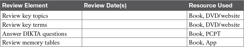
One key to doing well on the exams is to perform repetitive spaced review sessions. Review this chapter’s material using either the tools in the book, DVD, or interactive tools for the same material found on the book’s companion website. Refer to the “Your Study Plan” element for more details. Table 28-3 outlines the key review elements and where you can find them. To better track your study progress, record when you completed these activities in the second column.
Review All the Key Topics

Key Terms You Should Know
Application Policy Infrastructure Controller (APIC)
APIC Enterprise Module (APIC-EM)
Application Centric Infrastructure (ACI)
application-specific integrated circuit (ASIC)
ternary content-addressable memory (TCAM)
Software Defined Networking (SDN)
Representational State Transfer (REST)