
Chapter 4
802.11 Management Frames
In this chapter, you will learn about the following:
- Management Frame Types
- Beacons
- Probe Request / Response
- Authentication
- Association Request / Response
- Disassociation
- Deauthentication
- Reassociation Request / Response
- Management Frame body components
- Management Frame body main fields
- Management Frame body main Information Elements
- Action Frames
- Spectrum and Transmit Power Management (802.11h)
- Admission Control (802.11e)
- Fast BSS Transition (802.11r)
- Protected Management Frames (802.11w)
Management frames are often seen as the skeleton of wireless networks. They allow wireless devices to form a network and, as their name states, “manage” the connections. The original 802.11-1997 standard defined two types of management frames: the “notify” type and the “request and response” type. The “notify” type is a frame sent to the cell containing information to which no specific response is expected. The “request and response” type is an exchange between two stations or between an access point and a station.
In this chapter, we will examine each management frame. This task is complicated by the fact that the management frame body content is flexible, made of several elements where size is variable and presence is optional or mandatory, depending on the frame subtype and service provided to the cell. To help you get a clear understanding of these frames, we will show the structure of the main management frame types. We will then examine each field and information element, then by families. You will then take a closer look at a specific type of management frames, the action frames.
Figure 4-1 shows the structure of a management frame.
Figure 4-1: Management frame structure
Management frames always have a standard 24-byte-long MAC header with three addresses, followed by a body of variable size. When 802.11n is in use, the header is extended to show the HT Control section, as shown in Figure 4-2.
Figure 4-2: Management frame structure: 802.11n
The DA field is the destination address of the frame. It can be broadcast or unicast depending on the frame subtype. The SA field is the MAC address of the station transmitting the frame. The BSSID can be the AP BSSID or a wildcard value (see the “Probe Request” section).
The size and content of the body depend on the management frame subtype. Table 4-1 lists all 12 management frame subtypes, as defined by the 802.11-2007 standard.
Table 4-1: Management frame subtypes
| Subtype bits | Subtype description |
| 0000 | Association request |
| 0001 | Association response |
| 0010 | Reassociation request |
| 0011 | Reassociation response |
| 0100 | Probe request |
| 0101 | Probe response |
| 1000 | Beacon |
| 1001 | Announcement traffic indication message (ATIM) |
| 1010 | Disassociation |
| 1011 | Authentication |
| 1100 | Deauthentication |
| 1101 | Action |
| 1110 | Action no ack |
Type is always 00 (management). Some subtypes are “reserved” and currently unused (0110, 0111, and 1111).
Management frames are sourced and dealt with at the MAC layer and never forwarded to the upper layers. Management frames are always limited to the cell space; they are never relayed through an access point to the DS, from the DS, or from a station to another station. For this reason, management frames sent by access points always have the To DS and From DS fields set to 0.
Beacon Frame
Connecting to a wired network is often as simple as locating a connector on a switch or a wall, attaching the right cable, and plugging in your computer. Connecting to a wireless network presents more challenges. The AP may be hidden from view, in the ceiling, or in another room. You do not know which channel it uses and which modulations are supported. One way to learn about possible wireless connection points is to use passive scanning. With passive scanning, the wireless client tunes its radio to each possible channel in turn and listens for signals from access points. The speed and duration of dwelling time on each channel depends on the wireless client vendor driver and is defined in each driver MIB by the MaxChannelTime parameter.
Beacon frames are used by the access points (and stations in an IBSS) to communicate throughout the serviced area the characteristics of the connection offered to the cell members. Notice that this information is not only used by potential clients during passive scanning but also by clients that are already associated to the BSS.
Beacon frames are sent periodically, at a time called target beacon transmission time (TBTT) and at a rate defined by the dot11BeaconPeriod parameter in the AP MIB. All 802.11 device clocks count time by units of 1 kilomicrosecond each (in a world driven by powers of 2, this unit is 1,024 microseconds, not 1,000 microseconds). The dot11BeaconPeriod parameter is by default 100 time units (TUs), that is, 102,400 microseconds, which is a little over 102 milliseconds. This interval can be configured on some access points.
The access point tries to send the beacon at each defined TU interval and announces when the next beacon is expected to be sent. Nevertheless, access points are just like any wireless device in the cell. They cannot send if the network is busy. When the time comes for an AP to send a beacon, if the network is busy, the AP will delay its beacon transmission until it can gain access to the media. Although the beacon is slightly delayed, the AP will still try to send the next beacon at the originally planned interval. For example, suppose that a beacon is to be sent every 102.4 milliseconds, at times 0, 102.4, and 204.8. The first beacon is sent on time, but suppose the network is busy at time 102.4. The second beacon has to be delayed and can then be sent, for example, at time 103.2 millisecond and therefore 0.8 millisecond late. The AP will still try to send the third beacon at time 204.8 and will not delay that third beacon even if the previous one was late. Figure 4-3 illustrates this mechanism.
Figure 4-3: Beacon in busy network
All stations in the cell use the AP beacon as a time reference. Each beacon contains a time stamp and also an indication about when the next beacon will be sent. Each station uses the time stamp with what the 802.11 standard calls the timing synchronization function (TSF) to make sure that their clock uses the same tempo as the access point.
In an IBSS, stations use beacon frames for time synchronization and to maintain a common set of parameters for the IBSS. Because there is no central access point taking care of the beacon generation, the process is distributed. The first station to create the ad hoc network defines the beacon interval and announces it in the subsequent probe requests and responses. All stations joining the IBSS learn this interval. When the time comes for the next beacon, each station treats the beacon as the next packet to send. This means that each station of the IBSS does the following:
1. Interrupts its countdown for the next packet to send or wakes up if it was in Power Save mode.
2. Picks up a random number between zero and twice CWmin and 2× aSlotTime.
3. Counts down to zero from that number.
4. The first station to reach zero sends the beacon.
5. Hearing the beacon, the other stations remove the beacon from their network stack and resume their previous activity.
Figure 4-4 shows an example of a beacon capture. A beacon contains mandatory elements but also optional and vendor-specific elements. The size of the beacon body can therefore vary depending on the type of information carried by the beacon.
Table 4-2 lists the elements and fields you can expect to find (mandatory or optional) in a beacon frame body (see Figure 4-5). Most elements are defined in the 802.11-2007 standard. Some of them are introduced by specific amendments (and therefore used only by vendors implementing those amendments). The 802.11k amendment introduces processes for Radio Resource Management to help dynamically assign APs channels and power levels. The 802.11w amendment introduces the Management Frame Protection. The 802.11r amendment introduces Fast Basic Service Set transition (fast roaming between APs). The 802.11y amendment introduces the usage of a new band, 3650 to 3700, in the United States.
Figure 4-4: Beacon capture
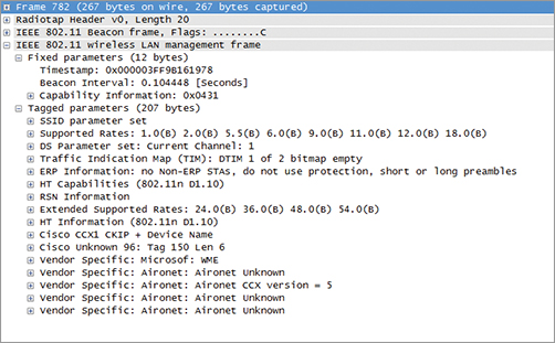
Figure 4-5: Beacon frame structure
Table 4-2: Elements and fields in a beacon frame body
| Order | Information | Note |
| 1 | Timestamp | |
| 2 | Beacon interval | |
| 3 | Capability | |
| 4 | Service Set Identifier (SSID) | |
| 5 | Supported rates | |
| 6 | Frequency-Hopping (FH) Parameter Set | Used by legacy FH stations. |
| 7 | DS Parameter Set | Present within beacon frames generated by STAs using clause 15, clause 18, and clause 19 PHYs or if the beacon is sent using one of the rates defined by one of these clauses. |
| 8 | CF Parameter Set | Used with PCF; unused in real networks. |
| 9 | IBSS Parameter Set | Present only within beacon frames generated by STAs in an IBSS. |
| 10 | Traffic indication map (TIM) | Present only within beacon frames generated by APs. |
| 11 | Country | Used with 802.11d and with 802.11. |
| 12 | FH Parameters | Used by legacy FH stations. |
| 13 | FH Pattern Table | Used by legacy FH stations. |
| 14 | Power Constraint | Used with 802.11h. |
| 15 | Channel Switch Announcement | Used with 802.11h. |
| 16 | Quiet | Used with 802.11h. |
| 17 | IBSS DFS | Used with 802.11h in IBSS. |
| 18 | TPC Report | Used with 802.11h. |
| 19 | ERP Information | Present in 802.11g networks; optional in other cases. |
| 20 | Extended Supported Rates | The Extended Supported Rates element is present whenever there are more than eight supported rates; it is optional otherwise. |
| 21 | RSN | Used with 802.11i. |
| 22 | BSS Load | Used with 802.11e QoS. |
| 23 | EDCA Parameter Set | Used with 802.11e QoS when the QoS Capability element is not present. |
| 24 | QoS Capability | Used with 802.11e QoS when EDCA Parameter Set element is not present. |
| 25–32, 34–36 | Vendor Specific | One or more vendor-specific information elements may appear in this frame. This information element follows all other information elements. |
| 33 | Mobility Domain | Used with 802.11r Fast BSS Transition. |
| 37 | HT Capabilities | Used with 802.11n. |
| 38 | HT Operation | Used with 802.11n. |
| 39 | 20/40 BSS Coexistence | Used with 802.11n. |
| 40 | Overlapping BSS Scan Parameters | Used with 802.11n. |
| 41 | Extended Capabilities | The Extended Capabilities element may be present if any of the fields in this element are nonzero. |
As a wireless LAN analysis professional, you should know each of these elements and understand their purpose. We will cover each of them later in this chapter.
Probe Request Frame
Discovering the network by scanning all possible channels and listening to beacons is not considered to be very efficient. At the scale of a wireless NIC, this process is seen as slow. To enhance this discovery process, stations often use what is called active scanning. In this mode, stations still go through each channel in turn, but instead of passively listening to the signals on that frequency, stations send a probe request management frame aimed at asking what network is available on this channel. If any AP or active station in an IBSS is present on that frequency, they should answer with the requested information. The probe request frame body contains the element and fields listed in Table 4-3.
Table 4-3: Elements and fields in a probe request frame body
| Order | Information | Note |
| 1 | Service Set Identifier (SSID) | |
| 2 | Supported Rates | |
| 3 | Request Information | Used with 802.11d. |
| 4 | Extended Supported Rates | The Extended Supported Rates element is present whenever there are more than eight supported rates; it is optional otherwise. |
| 5 | Vendor Specific | One or more vendor-specific information elements may appear in this frame. This information element follows all other information elements. |
The probe requests are usually sent to the broadcast DA address (ff:ff:ff:ff:ff:ff). The frame is sent using the common CSMA/CA procedure. Once the probe is sent, the emitting station starts a ProbeTimer countdown and waits for answers. This ProbeTimer value is decided by each vendor, but it is usually a lot shorter than a beacon interval. Common values are in the 10 millisecond range. At the end of the timer, the station processes the answers it has received. If no answer was received, the station moves to the next channel and repeats the discovery process.
Stations sending probe requests may specify the SSID they are looking for (in that case the probe request is called a directed probe request). Only those IBSS stations or APs supporting the requested SSID will answer. The SSID value can also be set to 0 (that is, the SSID field is present but empty). This is called a wildcard SSID, and the frame is a null probe request. In that case, an IBSS station or AP on the probed channel should send a probe response indicating the SSID it supports and the characteristics of the cell (see the next section).
The purpose of a probe request is typically to discover APs and their supported networks (SSIDs and/or BSSIDs). The station performing the discovery indicates the rates it supports so that the AP or IBSS station answering the probe request can determine the best data rate to use for the answer. The requesting station may also use the probe request to discover specific elements about the network (for example, “What are the local country parameters?”). To allow for this additional information discovery, the probe request can contain a Request Information element, shown in Figure 4-6, that can request one or several additional parameters.
Figure 4-6: Request Information element
This Request Information element is optional. The probe request may also contain additional, vendor-specific requests to exchange information specific to a vendor implementation of features that are optional or not described in the 802.11 standard.
Probe Response Frame
Upon receiving a probe request frame, a station in an IBSS or an AP will respond with a probe response frame, which contains information about itself and the cell (see Figure 4-7). The format of the probe response is very close to the format of a beacon, because both frames essentially answer the same question: what are the specs of the cell?
Figure 4-7: Probe response capture
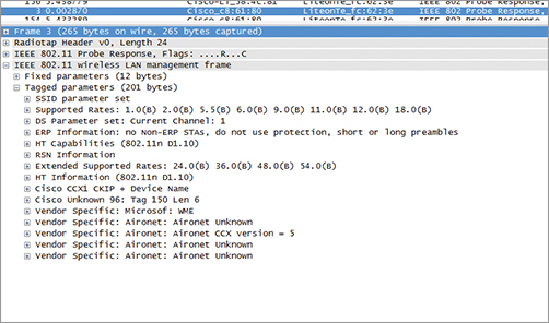
Table 4-4 lists the elements and fields you can expect to find (mandatory or optional) in a probe response frame body.
Table 4-4: Elements and fields in a probe response frame body
| Order | Information | Note |
| 1 | Timestamp | |
| 2 | Beacon interval | |
| 3 | Capability | |
| 4 | Service Set Identifier (SSID) | |
| 5 | Supported rates | |
| 6 | Frequency-Hopping (FH) Parameter Set | Used by legacy FH stations. |
| 7 | DS Parameter Set | The DS Parameter Set information element is present within beacon frames generated by STAs using clause 15, clause 18, and clause 19 PHYs. |
| 8 | CF Parameter Set | Used for PCF. Unused in real world. |
| 9 | IBSS Parameter Set | Used within beacon frames generated by STAs in an IBSS. |
| 10 | Country | Used with 802.11d and used with 802.11h. |
| 11 | FH Parameters | Used by legacy FH stations. |
| 12 | FH Pattern Table | Used by legacy FH stations. |
| 13 | Power Constraint | Used with 802.11h. |
| 14 | Channel Switch Announcement | Used with 802.11h. |
| 15 | Quiet | Used with 802.11h. |
| 16 | IBSS DFS | Used with 802.11h in an IBSS. |
| 17 | TPC Report | Used with 802.11h. |
| 18 | ERP Information | Used in 802.11g networks and optionally present in other cases. |
| 19 | Extended Supported Rates | The Extended Supported Rates element is present whenever there are more than eight supported rates; it is optional otherwise. |
| 20 | RSN | Used with 802.11i. |
| 21 | BSS Load | Used with 802.11e QoS. |
| 22 | EDCA Parameter Set | Used with 802.11e QoS when the QoS Capability element is not present. |
| 23 | Measurement Pilot Transmission Information | Used with 802.11k |
| 24 | Multiple BSSID | Used with 802.11k. |
| 25 | RRM Enabled Capabilities | Used with 802.11k. |
| 26 | AP Channel Report | Used with 802.11k. |
| 27 | BSS Average Access Delay | Used with 802.11k. |
| 28–30 | Reserved/unused. | |
| 31 | Mobility Domain | Used with 802.11r. |
| 32 | DSE Registered Location | Used with 802.11w. |
| 33 | Extended Channel Switch Announcement | Used with 802.11y. |
| 34 | Supported Regulatory Classes | Used with 802.11y. |
| 35 | HT Capabilities | Used with 802.11n. |
| 36 | HT Operation | Used with 802.11n. |
| 37 | 20/40 BSS Coexistence | Used with 802.11n. |
| 38 | Overlapping BSS Scan Parameters | Used with 802.11n. |
| 39 | Extended Capabilities | The Extended Capabilities element may be present if any of the fields in this element are nonzero. |
| Last-1 | Vendor Specific | One or more vendor-specific information elements may appear in this frame. This information element follows all other information elements. |
| Last-n | Requested information elements | Elements requested by the request information element of the probe request frame. |
The probe response is sent as a unicast frame. The DA field is the MAC address of the station from which the probe request was sent. The probe response is sent at the lowest common rate supported by both the station sending the probe request and the answering AP (or IBSS station). The probe response should be acknowledged by the receiving station, just like any other unicast frame.
If you compare this list to the beacon frame body component list, you will see that both frame bodies are very similar, with the following differences:
- The beacon frame contains a TIM field; the probe response does not.
- The beacon frame can contain a QoS Capability Information element that announces basic QoS support to the cell.
- The probe response also contains the Requested Information elements that may have been requested by the probing station.
Authentication Frame
Discovery is the first step a station should perform before trying to join the cell. The next step is the join phase, which is an exchange comprised of at least four frames: authentication request, authentication response, association request, and association response. You will learn in Chapter 9 that the process can be more complex and may include specific frame exchanges that provide authentication and data protection mechanisms. These mechanisms add frames to the standard 802.11 four frame authentication and association exchange mentioned earlier.
In all cases, after having performed a network discovery through the probe request/probe response exchange or by listening to beacons, a station wanting to join a cell goes through an authentication process, exchanging authentication frames with the access point. Unlike the probe and association phases, which use a different frame for the request and the response, there is only one type of authentication frame. Figure 4-8 shows its format.
Figure 4-8: Authentication frame format
The answer to an authentication frame is an acknowledgment frame. This is because authentication frames are always an exchange between a requesting station and a granting AP or IBSS station and are therefore always unicast frames. Unicast frames should be acknowledged to confirm proper delivery.
The initial purpose of the authentication frame is to validate the device type, in other words, verify that the requesting station has proper 802.11 capabilities to join the cell. This exchange is based on a simple two-frame dialogue (authentication request, authentication response) called the Open System. A possibility for a WEP shared key exchange was also included in the original 802.11-1997 standard. This shared key exchange adds two frames to the default Open System authentication, resulting in a four-frame exchange. This latter method is called Shared Key authentication, requires the use of WEP encryption, and is not widely used (or recommended) today.
The Authentication Algorithm number field value describes which authentication system is used (0 for Open System and 1 for Shared Key).
Notice that when more complex authentication is in place (such as with modern WPA and WPA2 security), Open System is used first, and then the more complex mechanism follows the 802.11 association.
In the authentication exchange, the 2-byte Authentication Transaction Sequence Number field indicates the current state of progress through the multistep transaction.
Depending on the exchange, the result of the authentication phase can be a successful authentication or a failure. The last frame of the authentication sequence contains the status code. 0 is Success, 1 is unspecified failure, and 2–9 are reserved values (they are used when the status field is present in the frame, but there is no status to report, for example because the frame is an authentication request). When the result is a failure (excluding unspecified failures), the code indicates the reason for the failure. The possible reasons are listed later in this chapter.
The 802.11 standard distinguishes the Reason Code field from the Status Code field. When a station negotiates a parameter, like authentication, the result of the negotiation is the status (success or failure). The AP or client can also suddenly send messages (such as a deauthentication or disassociation) interrupting the station communication without any negotiation. In that case, the AP justifies its action using the Reason Code field.
Table 4-5 summarizes the authentication frame field values and usage.
Table 4-5: Summary of authentication frame fields values and usage

Association Request Frame
If the 802.11 authentication phase completes with a Success result, the station moves to the association phase. The purpose of this exchange is for the station to join the cell and obtain a cell member identifier (called an association ID [AID]).
When a security authentication mechanism is in place, with WPA or WPA2, a second “authentication” phase occurs after the association phase. For this reason, the first authentication phase described earlier is called the 802.11 authentication phase to distinguish it from the later PSK or 802.1X authentication phase used with WPA or WPA2. It is important to note that the 802.11 authentication does not provide any security whatsoever. It is merely a formality. Notice that the WEP challenge uses the term shared key, whereas WPA/WPA2 refer to preshared key. Many vendors mix both terms or use other terms, such as passphrase, secret key, and so on.
The first frame sent in the association phase is from the requesting station to the AP (or a station in an IBSS). This frame is the association request frame and is shown in Figure 4-9. It is a unicast management frame and is always acknowledged. The SA is the requesting station MAC address, and the DA is the AP or IBSS station MAC address that was used for the authentication phase.
The association request body contains the elements and fields shown in Table 4-6.
Figure 4-9: Association request frame format
Table 4-6: Elements and fields in the association request body
| Order | Information | Notes |
| 1 | Capability Information | |
| 2 | Listen interval | |
| 3 | SSID | |
| 4 | Supported rates | |
| 5 | Extended Supported Rates | Present whenever there are more than eight supported rates; it is optional otherwise. |
| 6 | Power Capability | Used with 802.11h. |
| 7 | Supported Channels | Used with 802.11h. |
| 8 | RSN | Used with 802.11i. |
| 9 | QoS Capability | Used with 802.11e QoS. |
| 10 | RRM Enabled Capabilities | Used with 802.11k. |
| 11 | Mobility Domain | Used with 802.11r. |
| 12 | Supported Regulatory Classes | Used with 802.11r. |
| 13 | HT Capabilities | Used with 802.11n. |
| 14 | 20/40 BSS Coexistence | Used with 802.11n. |
| 15 | Extended Capabilities | The Extended Capabilities element may be present if any of the fields in this element are nonzero. |
| Last | Vendor Specific | One or more vendor-specific information elements may appear in this frame. This information element follows all other information elements. |
The details of each information element listed in this table will be covered later in this chapter. You can see that in the association request frame, the station communicates its characteristics and capabilities to the AP so that the AP can take note of how to communicate properly with this station.
Association Response Frame
After acknowledging reception of the association request frame, the AP examines each field of the request and verifies whether they all match its own 802.11 parameters (see Figure 4-10). If there is a mismatch, the AP decides whether this difference is a blocking (to the association) factor. If the difference is not blocking, the AP takes note of the limitations of the station parameters and grants access to the cell, indicating its own parameters in the association response. If the difference is blocking, the AP rejects the association.
Figure 4-10: Association response frame format

The rejected station is not associated to the cell. It can examine the answer from the AP, determine the reasons for the rejection, and correct its own parameters if possible before trying again. To allow for this mechanism, the association response frame contains the AP 802.11 parameters, as described in Table 4-7.
Table 4-7: The association response frame
| Order | Information | Notes |
| 1 | Capability Information | |
| 2 | Status Code | |
| 3 | Association ID | |
| 4 | Supported rates | |
| 5 | Extended Supported Rates | The Extended Supported Rates element is present whenever there are more than eight supported rates; it is optional otherwise. |
| 6 | EDCA Parameter Set | |
| 7 | RCPI | Used with 802.11k. |
| 8 | RSNI | Used with 802.11k. |
| 9 | RRM Enabled Capabilities | Used with 802.11k. |
| 10 | Mobility Domain | Used with 802.11r. |
| 11 | Fast BSS Transition | Used with 802.11r. |
| 12 | DSE Registered Location | Used with 802.11y. |
| 13 | Timeout Interval (association comeback time) | Used with 802.11w. |
| 14 | HT Capabilities | Used with 802.11n. |
| 15 | HT Operation | Used with 802.11n. |
| 16 | 20/40 BSS Coexistence | Used with 802.11n. |
| 17 | Overlapping BSS Scan Parameters | Used with 802.11n. |
| 18 | Extended Capabilities | The Extended Capabilities element may be present if any of the fields in this element are nonzero. |
| Last | Vendor Specific | One or more vendor-specific information elements may appear in this frame. This information element follows all other information elements. |
The AP also returns a status code informing the station whether the association is successful. If the result is Success (0), the AP communicates an association ID, which is the station identifier on the access point. The AID value is an integer between 1 and 2007. Although the field is 2 bytes long, only the 14 less significant bits are used (the others are set to 1). In reality, you would probably never see 2,007 stations associated to a single AP. The overhead required to maintain the cell state with so many stations would create so many collisions that the associations could never reach this number.
Once the station receives its association ID, it is associated to the cell and can start to communicate, sending data or moving to a second layer of authentication (see Chapter 9 for more details). If the association fails, the station receives in the status code the reason for the failure. Based on the status code and the parameters returned by the AP, it can modify its parameters and send a new association request frame, if the AP parameters are compatible with its own, or drop the association process and start looking for another AP, if the parameters are incompatible.
Disassociation Frame
Once a station is associated to an AP, either side can terminate the association at any time by sending a disassociation frame (see Figure 4-11). A station would send such a frame, for example, because it leaves the cell to roam to another AP. An AP could send this frame for example because the station tries to use invalid parameters or for reasons related to the AP itself (configuration change, and so on).
Figure 4-11: Disassociation frame format
The disassociation frame DA can be the unicast MAC address of the station to disassociate or a broadcast address if the AP needs to disassociate all the stations in its cell. When the disassociation frame is unicast, it is acknowledged by the receiving station. Broadcast frames are not acknowledged. The disassociation frame is quite small and contains the following elements:
| Order | Notes |
| 1 | Reason code. |
| 2 – (Last – 1) | One or more vendor-specific information elements may appear in this frame. |
| Last | Used with 802.11w. |
A disassociated station is still authenticated. It can try to reassociate by sending a new association request frame, keeping its authenticated status. For this reason, disassociation frames are typically used when parameters change and the station or the AP needs to renegotiate the communications parameters. A station roaming to another cell may also choose to use a disassociation frame, to be able to keep its authenticated status and accelerate the process when roaming back to the same cell before its authentication timeout expires.
Deauthentication Frame
The station or AP can also send a deauthentication frame. This frame is used when all communications are terminated, for example, because the AP has to reboot or because the station stops its Wi-Fi communications. It is also used when a frame is received before authentication has completed. For example, a station trying to send an association request or a data frame before having performed the authentication sequence will receive a deauthentication frame from the AP, indicating that authentication must be performed first.
The format of the deauthentication frame is the same as the disassociation frame, containing the following elements:
| Order | Notes |
| 1 | Reason code. |
| 2 – (Last – 1) | One or more vendor-specific information elements may appear in this frame. |
| Last | Used with 802.11w. |
Stations or APs receiving either of these frames recognize them by their type and subtype (00-1010 for the disassociation frame and 00-1100 for the deauthentication frame).
Reassociation Request Frame
This type of frame can be sent only by a station to an access point (never from an AP to a station or from a station to a station in an IBSS) and is used when the station is already associated to the ESS and wants to associate to another access point connecting to the same ESS. This frame (Figure 4-12) can also be used if the station left the cell for a short duration and wants to rejoin the cell again. This can occur while the station authentication is still valid on the AP or after the expiration of the authentication timer. In that case, the station first starts with an authentication phase, followed by the reassociation phase. A station already associated to an AP can also use the reassociation request message to renegotiate some parameters exchanged in the Association Request/Response dialog box.
The reassociation request frame is a unicast and acknowledged frame, just like the association request frame. It contains the elements shown in Table 4-8.
Figure 4-12: Reassociation request frame format
Table 4-8: Elements of the reassociation request frame
| Order | Information | Notes |
| 1 | Capability Information | |
| 2 | Listen interval | |
| 3 | Current AP address | |
| 4 | SSID | |
| 5 | Supported rates | |
| 6 | Extended Supported Rates | The Extended Supported Rates element is present whenever there are more than eight supported rates, and it is optional otherwise. |
| 7 | Power Capability | Used with 802.11h. |
| 8 | Supported Channels | Used with 802.11h. |
| 9 | RSN | Used with 802.11i and 802.11y. |
| 10 | QoS Capability | Used with 802.11e QoS. |
| 11 | RRM Enabled Capabilities | Used with 802.11k. |
| 12 | Mobility Domain | Used with 802.11r. |
| 13 | Fast Transition | Used with 802.11r. |
| 14 | Resource Information Container | Used with 802.11r. |
| 15 | Supported Regulatory Classes | Used with 802.11y. |
| 16 | HT Capabilities | Used with 802.11n. |
| 17 | 20/40 BSS Coexistence | Used with 802.11n. |
| 18 | Extended Capabilities | Used with 802.11n. |
| Last | Vendor Specific | One or more vendor-specific information elements may appear in this frame. This information element follows all other information elements. |
The logic of the reassociation request was linked to roaming. In this logic, the station leaves the coverage area of an access point and needs to associate to another access point offering the same SSID. This roaming station goes through the authentication phase with the new access point, then sends a reassociation request mentioning the old AP MAC address, and finally joins the cell on the new AP, getting a new AID.
Why not proceed with a simple association request frame? It’s because the logic is that the new access point should contact the old access point and move the parameters for the station from the old AP to the new one. A station can be associated to only one AP at a time. It is therefore the responsibility of the new AP to inform the old AP about the roam and disassociate the station from the old AP.
A station can be authenticated to several access points, as long as it is associated to only one of them.
Reassociation Response Frame
An AP uses the reassociation response frame in response to a reassociation request frame. The reassociation response contains the elements shown in Table 4-9.
Table 4-9: Elements of the reassociation response frame
| Order | Information | Notes |
| 1 | Capability Information | |
| 2 | Status Code | |
| 3 | Association ID | |
| 4 | Supported rates | |
| 5 | Extended Supported Rates | The Extended Supported Rates element is present whenever there are more than eight supported rates, and it is optional otherwise. |
| 6 | EDCA Parameter Set | Used with 802.11e QoS. |
| 7 | RCPI | Used with 802.11k. |
| 8 | RSNI | Used with 802.11k. |
| 9 | RRM Enabled Capabilities | Used with 802.11k. |
| 10 | RSN | Used with 802.11i and 802.11r. |
| 11 | Mobility Domain | Used with 802.11r. |
| 12 | Fast BSS Transition | Used with 802.11r. |
| 13 | RIC | Used with 802.11r. |
| 14 | DSE Registered Location | Used with 802.11y. |
| 15 | Timeout Interval (Association Comeback time) | Used with 802.11w. |
| 16 | HT Capabilities | Used with 802.11n. |
| 17 | HT Operation | Used with 802.11n. |
| 18 | 20/40 BSS Coexistence | Used with 802.11n. |
| 19 | Overlapping BSS Scan Parameters | Used with 802.11n. |
| 20 | Extended Capabilities | The Extended Capabilities element may be present if any of the fields in this element are nonzero. |
| Last | Vendor Specific | One or more vendor-specific information elements may appear in this frame. This information element follows all other information elements. |
As you can see, its format is exactly the same as the association response frame. The only difference is its position in the exchange (it has to be preceded with a reassociation request frame) and the consequence of the exchange. With association request/response, the station gets an AID on the local AP. With reassociation request/response, the station details have to be moved from the old AP to the new AP.
Exercise 4-1
Viewing an Association Sequence
In this exercise, you will use a protocol analyzer to view a complete 802.11 association sequence. The following directions should assist you with the installation and use of Wireshark Packet capture software. If you have already installed Wireshark, you can skip steps 1–2.
1. Open the CD provided with this book.
2. Under Product Evals, choose Wireshark, double-click to start the installation process, and follow the installation prompt.
3. In Windows, choose Start Programs Wireshark. The Wireshark application should appear.
4. Click the Open Capture File icon, and browse the book’s CD. Open the packet capture file called ch04_capture1.PCAP.
5. When you click a packet, its details appear in the lower window. You can use the + sign to expand each element.
6. Navigate to frame 703, and examine frames 703 and 705. They are the probe request/exchange that precedes the authentication phase.
7. Examine frames 715 to 718. They are the authentication phase, using Open System.
8. Examine frames 719 to 722. They are the final association phase.
ATIM Frame
The ATIM frame is specific to IBSS networks and used for distribution of buffered frames to stations in sleep mode in the ad hoc network.
Beacons in IBSS are sent by any participating station. There is an ATIM window in the beacon to indicate that participating stations should not fall back to doze mode. During the ATIM window, the ATIM frame is used to distribute broadcast and multicast packets, just like the DTIM in infrastructure networks, and also when new stations want to join the ad hoc network. You will learn more about ATIM in Chapter 8.
Action Frame
Action frames form the 12th and last type of management frame. They are used to trigger specific actions in the cell. Figure 4-13 shows their format.
Figure 4-13: Action frame format

We will cover them in more detail later in this chapter.
Information Elements and Fields
Management frame bodies consist of fields and information elements. A field is a section of the frame body that is always present for a given type of frame and has a static size. An information element is a section of the frame body that can be of fixed or variable size, depending on its content, and may be present or not, depending on the features supported by the AP or station sending the frame.
For example, beacon frames contain a Beacon Interval field. This section of the beacon is a field because it is always present and always has the same size. Beacon frames also contain a Supported Rate element. This is an element, because although it is always present, its size may vary from 1 to 8 octets. Similarly, the SSID section of the beacon is also called an element, because its size is variable. Beacon frames also contain a QoS Capability element, the size of which is fixed (1 octet). This is an element, because it is present only if the emitting station or AP supports QoS.
As a wireless analysis professional, you should know the various possible fields and elements you may see in a frame capture to be able to determine whether all elements are present, whether unexpected elements are present, and whether each field or element encountered presents abnormal values.
We will first cover the fields and then the main possible information elements, starting with those that you will see in most frames, before focusing on the more uncommon types. Notice that the management frames can contain some information elements not described in this chapter. We focus on the main elements found in most packet captures.
Management Frame Fields
Management frame fields are usually found at the beginning of the frame body.
Timestamp Field
The timestamp field is 8 bytes long, as represented in Figure 4-14. It can be found in beacons and probe responses.
Figure 4-14: Timestamp field
You know now that the timestamp is a value representing the time on the access point, which is the number of microseconds the AP has been active. When that timestamp reaches its maximum value, the counter is simply reset and restarts from zero. Nevertheless, because the Timestamp field is 8 bytes long, the AP would need to be running for more than 580,000 years before this field reaches its maximum value! Of course, no one expects any AP to be running that long. The logic was that this field should need to have a length that would be a power of two: 2, 4, or 8 bytes. Four bytes would allow for only 71 minutes before the field would reach its maximum, which was too short. This is why the next logical value, 8 bytes, was chosen.
The stations in the cell use that timestamp value to adjust their own clock (using their Time Synchronization Function).
Beacon Interval Field
The Beacon Interval field represents the number of time units between target beacon transmission times (TBTTs). The length of the Beacon Interval field is 2 octets. Figure 4-15 illustrates the Beacon Interval field.
Figure 4-15: Beacon Interval field
The default value is 100 TUs (0.102400 seconds), but the field size allows for any value between 1 and more than 67 seconds! Nevertheless, most stations’ drivers allow only a small variation from the default value. If the interval between beacons is too short, stations using Power Save mode might not be able to doze and wake up fast enough, creating collisions in the cell and disconnections. If the interval is too long, stations using the beacon as a sign that the network is still available may disconnect because the interval exceeds their waiting capacity. This long interval also creates traffic issues because more traffic is buffered at the AP while non-QoS stations are sleeping between beacons.
Capability Information Field
The Capability Information field is more complex than the other fields, because it contains a number of subfields that are used to indicate requested or advertised optional capabilities.
The length of the Capability Information field is 2 octets. The format of the Capability Information field is defined in Figure 4-16.
Notice that this Capability Information field exists in several management frames (beacons, probe response, association request, association response, reassociation request, and reassociation response). For this reason, each Capability Information subfield is interpreted according to the management frame subtype.
Many of these fields show optional features that can be implemented or not. This section shows only the main items.
Figure 4-16: Capability Information field
ESS/IBSS Subfields
The ESS bit indicates whether the beacon is coming from an AP (1) or not (0). The IBSS bit indicates whether the beacon is coming from an IBSS station (1) or not (0).
Privacy Subfield
APs set the Privacy subfield to 1 if data confidentiality is required for all data frames exchanged within the BSS. If data confidentiality is not required, the Privacy subfield is set to 0. Data confidentiality means any type of encryption (AES, TKIP, or WEP). The mechanism by which the encryption type is decided is determined by the presence of other fields in the beacon, in particular field 21, RSN. The Privacy field only shows the requirement (or not) for encryption when sending data frames.
Short Preamble Subfield
You learned about the short and long preamble in Chapter 2. The short preamble is set to 1 in beacons when short preambles are allowed (therefore, stations can use short or long preambles). This field is set to 0 when short preambles are not allowed, and only long preambles should be used.
Channel Agility Subfield
Channel Agility was an optional feature introduced when the 802.11b protocol was released. Its aim was to offer the possibility for the center channel to shift periodically slightly up and down, in the hopes of avoiding interferences. The Channel Agility feature was never widely implemented. It is still present as a possibility in the Capability field, but only for HR/DSSS stations (OFDM does not implement this feature).
Spectrum Management Subfield
This subfield is linked to the 802.11h amendment. When APs and clients operate on the affected section of 5 GHz in countries where 802.11h compliance is mandatory, they must set their Spectrum Management field to 1 to reflect that they implement DFS and TPC.
The Spectrum Management subfield is set to 0 when the cell operates on a channel unaffected by the 802.11h amendment or in a country where 802.11 compliance is not required.
QoS Subfield
As its name states, this field shows whether the AP supports QoS. Do not get confused by the many QoS fields in 802.11 management frames! In a beacon frame, field 24, QoS Capability, provides more details about how QoS is supported in the cell. In frame headers, the QoS Control field also provides details about that particular frame’s QoS characteristics. The QoS subfield in the Capability Information field simply tells the cell “I can do QoS; look for other QoS fields in my frames.”
Short Slot Time Subfield
Slot time and SIFS are the two values from which all other interframe spaces and countdown values are defined. Standard slot time used to be 20 µs with 802.11 and 802.11b and was reduced to 9 µs with 802.11g (802.11a also uses 9 µs slot times). This subfield determines whether short slot time is allowed in the cell (the Short Slot Time subfield set to 1), which is a clear sign that the AP is not supporting 802.11b. There are a few details you need to remember:
- If at least one station joins the cell and cannot support short slot time (the station is 802.11b only), then short slot time should be disabled entirely in the cell, and this subfield will be set to 0 in the subsequent beacons, until the 802.11b station disconnects.
- The rule is a bit different for 802.11a networks! The 802.11a specification describes three slot times, depending on the interchannel spacing (9 µs for 20 MHz spacing, 13 µs for 10 MHz spacing, or 21 µs for 5 MHz spacing). Because 20 MHz spacing is in use in standard networks, 9 µs should be the standard slot time, and there is no short slot time (because there is no long slot time!). The Short Slot Time should therefore be disabled and set to 0 for 802.11a networks, but this implementation is vendor-dependant, so you might find both 0 and 1 values.
- For IBSS networks, short slot time should always be set to 0, which means that IBSS networks never support short slot times.
APSD Subfield
Automatic Power Save Delivery (APSD) is an enhancement introduced by the 802.11e specification. When this APSD bit is set to 1, the AP supports the 802.11e APSD feature. When the bit is set to 0, the AP only supports the legacy Power Save mode. Notice that stations sending capability information to the cell (in association or reassociation requests) always set that subfield to 0, because this feature is a function of the entire cell, not individual station decisions.
DSSS-OFDM Subfield
This subfield name is self-explanatory. DSSS-OFDM provides 54 Mbps speeds in 802.11b/g-compatible networks. When this bit is set to 1, the DSSS-OFDM mode is allowed in the cell. When the bit is set to 0, this mode is not allowed. This rule is also valid for an IBSS.
This bit is always set to 0 for 802.11a networks.
This bit set to 0 does not mean that 802.11g is not allowed but simply that the hybrid DSSS-OFDM mode, allowing frames with a DSSS preamble and header followed by an OFDM PPDU as its PSDU, is not allowed. Stations may still be able to perform at 802.11g speeds, using protection when 802.11b stations are detected. The Supported Rates and Extended Supported Rates field of the beacon frame body will inform the stations about which rates and which modulations are allowed.
Listen Interval Field
In frames sent from stations to access points (association request, reassociation request), the Listen Interval field is used to indicate to the AP how often a station in Power Save mode wakes to listen to beacon management frames. This value is an integer expressed in beacon interval units (for example, a value of 3 indicates that the station wakes up every three beacons). This field is 2 bytes long, which means that the maximum interval could be 65,535.
All other values of authentication number are reserved.
Status Code Field
The Status Code field is used in a response management frame to indicate the success or failure of a requested operation. You will find this field in the authentication response frame, the association response frame, and the reassociation response frame. This field is 2 bytes long. If an operation is successful, then the status code is set to 0. If an operation results in failure, the status code indicates a failure cause. However, status code 1 indicates an unspecified failure.
Association ID Field
The AID field is a value assigned by an AP during association that represents the 16-bit ID of an STA. The length of the AID field is 2 octets. The value assigned as the AID is in the range 1–2007 and is placed in the 14 low-weight bits of the AID field, with the two high-weight bits of the AID field each set to 1.
Reason Code Field
This Reason Code field is used to indicate the reason that an unsolicited notification management frame of type disassociation, deauthentication, DELTS, DELBA, or DLS teardown was generated. Don’t confuse this field with the Status Code field! The Status Code field indicates if a request is successful and details the cause of the failure. The Reason Code field is present only when the frames listed earlier are sent to a station without the station asking for any negotiation of any parameter.
Action Frame–Related Fields
There are several other fields that are found only in action frames and their related responses. These fields will be covered in the “Action Frames” section of this chapter.
Exercise 4-2
Viewing Beacon Frame Fields
In this exercise, you will use a protocol analyzer to view the 802.11 beacon. The following directions should assist you with the installation and use of the Wireshark Packet capture software. If you have already installed Wireshark, you can skip steps 1–2.
1. Open the CD provided with this book.
2. Under Product Evals, choose Wireshark, double-click to start the installation process, and follow the installation prompt.
3. In Windows, choose Start Programs Wireshark. The Wireshark application should appear.
4. Click the Open Capture File icon, and browse the book’s CD. Open the packet capture file called ch04_capture2.PCAP.
5. When you click a packet, its details appear in the lower window. You can use the + sign to expand each element.
6. Compare the structure of packet 6 and packet 7. You should see two differences in the fields of each beacon:
- The beacon interval is different. It uses the default TBTT for frame 7 but a longer interval for frame 6.
- Frame 6 allows short preambles, while frame 7 does not.
- All other fields indicate the same values.
As a wireless professional, you should also be able to read the Radiotap Header section to verify on which channel and at what speed the frames were received.
Management Frame Information Elements
All the other fields present in the management frames are called information elements (IEs). Remember that they are called this because they may or may not be present or their size may vary. All information elements have the same structure: at least three subfields, the first one being an element ID (defined by the 802.11 standard), the second defining the length of the element, and the remaining fields being the element itself, as shown in Figure 4-17.
Figure 4-17: Generic information element format

Extended Capabilities Element
The Extended Capabilities element is an extension of the Capability Information field; it adds capabilities that would not be covered by the Capability Information field. As such, it is present in the same types of frames: beacons, probe responses, association requests, association responses, reassociation requests, and reassociation responses. Figure 4-18 shows the format of the Extended Capabilities element.
Figure 4-18: Extended Capabilities element
Several amendments use this element. Among them, 802.11y describes the 3650-3700 band operations in the United States and uses the Extended Capabilities element with an option identifier 2 for a feature called extended channel switch announcement (ECSA). This feature is close to the 802.11h amendment channel switch announcement feature. The AP scans the available channels and informs the stations about the next, better channel they should all jump to. The 802.11n amendment also uses the Extended Capabilities elements. You will learn more about 802.11n in Chapter 10.
SSID Element
The SSID element is present in all beacons, probe requests, probe responses, association requests, and reassociation requests. Figure 4-19 shows the format of the SSID field.
Figure 4-19: SSID element
The element ID is 0. The length section defines the length of the SSID string, in octets. The SSID string is a text string, with each character being coded over one octet. It contains as many octets as it has characters, with a maximum of 32 characters.
Notice that some APs support Multiple Basic Service Set Identifier (MBSSID) features, by which an AP can offer several SSIDs on the same radio. In this case, most vendors simply send as many beacons as they support SSIDs. If your AP is expected to send a beacon every 100 TUs and your AP supports 5 SSIDs, the AP will send one beacon every 20 TU, advertising its capabilities for each SSID in turn.
Supported Rates Element
The Supported Rates element is present in beacons, probe requests, probe responses, and all association frames (association request, response, reassociation request/response). This element specifies up to eight rates. This was more than enough for the legacy 802.11 rates and is still perfectly fine for 802.11b. Since the introduction of OFDM rates, this field became too small, and a second field was added at the end of the beacon to list the additional supported rates. In the Supported Rates field, the length field is encoded as 1 to 8 octets, where each octet describes a single supported rate. When both Supported Rates and Extended Supported Rates fields are used, which particular individual rate appears in which field is of no importance, as long as all rates are mentioned. Most vendors just list them in order.
Figure 4-20 defines the format of the Supported Rates field.
Figure 4-20: Supported Rates element

Each rate is listed over one octet, with the following logic:
- The last bit (bit 7) is set to 1 if the rate is a basic rate (or mandatory rate) and set to 0 if the rate is simply supported.
- The other seven bits (bits 0 to 6) are set to the data rate, if necessary rounded up to the next 500 Kbps, in units of 500 Kbps.
For example, a 5.5 Mbps rate contained in the BSSBasicRateSet parameter is encoded as 10001011 (10000000 because it is set to Basic Rate, and binary 1011 for decimal 11, because 5.5 Mbps are 11 times 500 kbps); 2 Mbps supported would be 00000100.
Any station wanting to join the cell must support all mandatory/basic rates. The 802.11 standard defines, by default, several basic rates, which represent each possible modulation of the protocol. Leaving these defaults ensures that all stations joining the cell understand all the modulations in use in the cell. This is the reason why, for example, you will find 6, 12, and 24 Mbps as default mandatory rates for 802.11a networks, ensuring that joining stations understand BPSK (6, 9 Mbps), QPSK (12, 18 Mbps), and QAM (24 Mbps and higher). This parameter can usually be configured on an access point, but at least one mandatory rate must be set, because this first mandatory rate is going to be used to determine the “common rate” understood by all stations, at which many broadcast frames will be sent. As explained earlier, the first mandatory rate is usually the lowest supported rate so that the footprint reached by frames such as probes and beacons matches the footprint of the cell itself.
Extended Supported Rates Element
The Extended Supported Rates element specifies the supported rates not carried in the Supported Rates element. It is present in beacons, probe requests and probe responses, and all association frames (association request/response, reassociation request/response). The information element is encoded as 1 to 255 octets where each octet describes a single supported rate. Figure 4-21 defines the format of the Extended Supported Rates field.
Figure 4-21: Extended Supported Rates element
The rate structure is the same in this field as in the Supported Rates field. The first 7 bits (bits 0 to 6) express the rate in units of 500 Kbps. The last bit (bit 7) is set to 1 if the rate is configured as Basic (or mandatory) and set to 0 otherwise.
The Extended Supported Rates field is of course necessary only if there are more than eight supported rates. If there are eight or fewer supported rates, only the Supported Rates field is used.
Extended Rate PHY (ERP) Element
The ERP element is present only on 2.4 GHz networks supporting 802.11g and is present in beacons and probe responses. Figure 4-22 shows the format of the Extended Supported Rates element.
Figure 4-22: ERP element

This field is essential to the operation of 802.11b/g/n networks.
You probably remember from your CWNA the protection mechanisms in place in 802.11b/g networks when 802.11b clients are detected. The ERP field regulates how the presence (or absence) of 802.11b devices is transmitted to the cell.
The NonERP_Present bit is set to 1 if at least one of the following conditions occurs:
- A nonERP station (legacy 802.11 or 802.11b) associates to the cell.
- A neighboring cell (BSS or IBSS) is detected, allowing only nonERP data rates. This detection is expected to occur by receiving a beacon from the neighboring cell.
- Any other management frame (except probe requests) is received from a neighboring cell supporting only nonERP data rates.
Notice the word associates in the first condition. This means that, as per the 802.11-2007 protocol, the NonERP_Present bit should be set to 1 only when the association phase completes for a nonERP station (the legacy 802.11 or 802.11b station is completely associated to the cell). Nevertheless, many vendors have a broader understanding of the association process and consider that a probe request is the first step toward a complete association. This is why many vendors implement the nonERP_Present bit as soon as an 802.11 or 802.11b station is detected, even if this detection is limited to probes. This is an extension to the protocol but is a common and valid behavior.
The UseProtection bit is set to 1 as soon as a nonERP client is associated to the cell. This bit informs ERP clients that they have to use a protection mechanism (RTS/CTS or CTS to self) before sending. The UseProtection bit is also linked to the concept of “association,” at least in the 802.11-2007 protocol. The same protocol defines a larger use case for this bit in an IBSS. Because there is no concept of “association” per se in an IBSS, any station detecting a member of the IBSS supporting only nonERP rates can set the UseProtection bit warning message in its frames. The UseProtection bit is heard and repeated by the other members of the IBSS so that all IBSS ERP members get informed. This behavior was extended by many vendors to standard BSSs. This means that most of the time, the simple detection of a management frame, even coming from a neighboring cell, displaying the UseProtection bit set to 1 will trigger the local AP to set its UseProtection bit to 1.
This behavior makes a lot of sense. The nonERP present bit is set to 1 only if the AP detects a non-ERP station in the cell. If the AP detects a beacon from a neighboring AP having the UseProtection bit set to 1, there may be a nonERP station in the neighboring cell that can impact the traffic of the local cell clients in the direction of this neighbor, even if the local AP does not hear the nonERP client directly. Figure 4-23 illustrates this case.
Figure 4-23: UseProtection ripple
Asking the local cell clients to use protection anyway is a good way to avoid that this hidden nonERP client (hidden from the local AP standpoint) disrupts the cell communications.
In the same ERP field, the Barker Preamble Mode subfield is set to determine whether, when using protection, short preambles are allowed (Barker Preamble Mode set to 0) or whether only long preambles should be used (Barker Preamble Mode set to 1).
Bits r3 to r7 are unused and ignored. They were set as padding and for possible future expansion of the ERP Element. This expansion hasn’t occurred so far. There is a protection mechanism for 802.11n, but it uses another field called the HT Protection field.
Robust Security Network (RSN) Information Element
This element is crucial when using WPA/WPA2 to determine the authentication and encryption mechanisms in place in the cell. The Privacy subfield in the Capability Information field was enough when the only choice was WEP or Open. Now that several mechanisms are in place, a more complete communication is needed between the AP and its potential clients to specify how to authenticate to the cell and encrypt traffic. You will learn more about this element component in Chapter 9.
The RSN element has an element ID of 48 and is present in beacons, probe responses, association responses, and reassociation responses. Figure 4-24 shows the structure of the RSN element.
Figure 4-24: RSN element
The element size is flexible and depends on how many authentication and encryption mechanisms are allowed.
Beyond the usual element ID and length, the first field, Version, is always set to 1. It is 2 bytes long, which leaves some room for future versions!
Just after the Group Cipher Suite descriptor, individual ciphers are listed to protect unicast frames. As several ciphers may be allowed, the Pairwise Cipher Suite Count field is here to state how many ciphers are allowed. Then, each cipher is listed in an individual Pairwise Cipher Suite List field. Each field is of course 4 bytes long, because each cipher is represented over 4 bytes. There is no limitation in the number of ciphers listed, except that the entire RSN element should not exceed 255 bytes.
When a station supports several ciphers, it always chooses the strongest one first (in order: CCMP, TKIP, WEP 104, WEP 40).
Now that the ciphers allowed in the cell are defined, you still need to inform potential cell clients about how they are supposed to authenticate in order to join the cell. This is done with the Authentication and Key Management (AKM) section. The AKM Suite count defines the number of methods allowed, and the AKM Suite list displays each individual method. Just like for the cipher, each method is coded over 4 bytes: the first 3 bytes are an OUI, and the last byte is one of the methods supported by the vendor matching the OUI. The 802.11i committee defined two methods—00-0F-AC-1 for 802.1X or PMK caching and 00-0F-AC-2 for PSK—but any vendor-specific method is possible, provided that clients and APs support it.
Basic Service Set (BSS) Load Element
This element is used only when QoS is supported (when the QoS subfield in the Capability Information element is set to Enabled). It is often called QBSS Load element. It provides information on the cell load, from the AP point of view. It is typically sent by the AP (although the 802.11 standard does not restrict it to APs only) and used by the receiving stations to decide how to roam.
Figure 4-25 defines the format of the BSS Load element.
Figure 4-25: BSS Load element
The station count is a simple number, showing how many stations are currently associated to the cell. The term associated is understood to apply to stations completely associated, not to probing stations.
The Channel Utilization field is defined as the percentage of time, normalized to 255, that the AP sensed the medium was busy, as indicated by either the physical or virtual carrier sense mechanism.
The AP senses the medium, just like any other station, every slot time. At regular intervals (every 50 beacons by default, which represents 5.12 seconds if the beacons are sent at 100 TU intervals), the AP looks over the last period and counts how many times the network was seen as busy and how many times the network was seen as idle. The AP then calculates a simple percentage and translates it into a 0 to 255 range.
This information is used by QoS stations to gauge the space available on several APs in range.
Enhanced Distributed Channel Access (EDCA) Parameter Element
This element is used only when QoS is supported. You will learn more about QoS detailed mechanisms in Chapter 7. This section is a summary. In most QoS-enabled networks, this field is not used, and the same information is provided through the WMM or the WME vendor-specific element.
QoS Capability Element
This element is used only when QoS is supported. It is used as a replacement to the EDCA Parameter element when EDCA Parameter is not present. It is also used by the AP to communicate to the cell the QoS information. It is a shorter version of the EDCA Parameter Set element and contains only the QoS information section. In most QoS-enabled networks, this field is not used, and the same information is provided through the WMM or the WME vendor-specific element.
Direct Sequence Parameter Set Element
This element is used by both the DSSS and OFDM systems, on both 2.4 GHz and 5 GHz spectrums. It is a very important field that simply indicates the current channel. Figure 4-26 shows the format of the DS Parameter Set element.
Figure 4-26: DS Parameter Set element
This element is key for proper operation of 802.11 networks, because 802.11 signals spread across several channels. This tells the receiving station on which channel the emitter is centering its signal. The value is simply the channel number.
When using 802.11n and channel bonding, this element focuses on the primary channel. The secondary channel information is displayed in several 802.11n-specific fields, such as the Secondary Channel information element or the 20/40 BSS Coexistence element. You will learn more about these elements in Chapter 10.
Traffic Indication Map (TIM) Element
This element is present only in beacons. The TIM element contains information useful for stations in low-power mode. Figure 4-27 shows the format of the TIM field.
Figure 4-27: TIM element
Besides the classical element ID and length, the TIM contains two types of elements: the virtual bitmap and the DTIM information.
The DTIM is not present in all beacons and all TIMs. At regular intervals (usually configurable on the AP), the beacon will contain a TIM that will also be a DTIM. The DTIM purpose is easy to understand. The AP uses the beacon frames Delivery Traffic Indication Message (DTIM) information to inform the cell if it has broadcasts or multicasts frames buffered. Stations in low power mode should wake up at least for every beacon that is a DTIM. The DTIM does not have to be in every beacon but can, for example, occur every two to five beacons. The DTIM is contained in the TIM, so in that case it is said that the TIM is also a DTIM.
In the TIM field, the DTIM period element indicates the number of beacon intervals between successive DTIMs (for example, 3 means every third beacon is a DTIM). The DTIM Count field indicates how many beacon frames (including the current frame) appear before the next DTIM. A DTIM Count field of 0 indicates that the current TIM is a DTIM. A DTIM count of 1 indicates that the next beacon is a DTIM.
When a DTIM shows that there is broadcast or multicast traffic buffered at the AP level, all stations stay awake. Just after sending the beacon announcing that buffered broadcast or multicasts the AP contends for the medium and then forwards the buffered broadcast or multicast to the cell. All stations receive it and then can go back to sleep if needed. Multicast and broadcast traffic is of course never acknowledged.
The first bit of the bitmap control field is used to announce the presence of multicast or broadcast traffic buffered on the AP. Figure 4-28 illustrates this case.
Figure 4-28: DTIM multicast present

When the first bit of the Bitmap Control field is set to 1, the AP has multicast or broadcast buffered. When this first bit is set to 0, there is no buffered broadcast or multicast. Notice that this analyzer (Wireshark) displays mcast, for multicast, but there is no way of knowing from the DTIM information whether the buffered traffic is broadcast or multicast. Some analyzers will display multicast, some others broadcast, and some others broadcast/multicast.
The next 7 bits of the Bitmap Control field, along with the virtual bitmap, represent the stations in low power mode for which the AP has traffic buffered. You will learn more about this process in Chapter 8.
IBSS Parameter Set Element
This element is present only on probe responses and beacons of stations in an IBSS. Figure 4-29 shows the format of the IBSS Parameter Set element.
Figure 4-29: IBSS Parameter Set element
Just like the TIM, the Announcement Traffic Indication Message (ATIM) window displayed in the IBSS Parameter Set element is used for power save (see Figure 4-30).
Figure 4-30: IBSS DFS element
So, there is only one map, and there are two messages. In ATIM, A is Announcement, even if it is used for ad hoc networks.
You will learn more about ATIM in Chapter 8.
The first station to start the IBSS is determined as being the DFS owner. It determines the 802.11h operations in the cell. The DFS Owner MAC address is mentioned in the IBSS DFS Field, although it is present as the SA of the frame. If the DFS owner disappears or is lost during a jump, the IBSS DFS field defines a DFS Recovery Interval (expressed in TBTTs or beacon intervals), which is a form of timeout. A station not hearing from the DFS owner for longer than the DFS recovery interval will select its own channel and assume the role of DFS owner.
The last field of the IBSS DFS element is a list of possible channels.
Country Element
Each country has regulatory bodies that can limit the channels or power levels allowed in their regulatory domain. Instead of having to update all drivers of all wireless devices every time regulations change in a country, the 802.11 standard introduced the idea, via the amendment 802.11d, to send the local regulatory values from the AP. The Country field defines the country of operation, along with the allowed channels and maximum transmit power. It is not a mandatory field and is typically found on APs that can support several country settings.
Figure 4-31 shows an example of a capture with a country code.
Figure 4-31: Capture with Country element
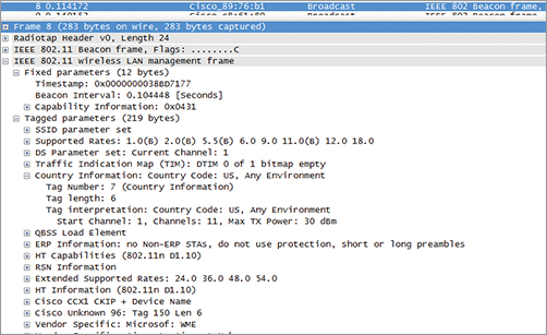
Refer to Figure 4-4 earlier in this chapter for an example of a capture on an access point not implementing the Country field. That AP was of SOHO type and built for only one country of operation. The AP used for Figure 4-31 is of Enterprise type and offers options to enable or disable the Country field.
Power Constraint Element
This element is related to 802.11h. In countries where compliance with 802.11h is implemented, stations operating in the 5 GHz bands should reduce their power level so as not to disturb with too powerful emissions other devices using the same spectrum. This limitation is called satellite services, although it is so far implemented only to avoid interference with civilian airport radars in the UNII-2 and UNII-2 extended bands. The mechanism is that each country has a maximum power value that can be known from the wireless device or learned from the AP via the Country field. In the Power Constraint field, the AP indicates how much lower than this maximum power participants should try to go.
TPC Report Element
This element is also related to 802.11h. The TPC Report element contains transmit power and link margin information, usually sent in response to a TPC Request element. We will look at this element more closely at the end of this chapter.
Channel Switch Announcement Element
This element is also related to 802.11h. When a radar blast is detected, all stations must leave the affected channel. The AP can be set to announce to the cell which is the next channel. We will look at this element more closely in the “Spectrum and Transmit Power Management” section of this chapter.
Quiet Element
This element is also related to 802.11h. An AP can request a quiet time during which no stations should transmit in order to test the channel for the presence of radars. We will look at this element more closely in the “Spectrum and Transmit Power Management” section of this chapter.
The following elements are also present in 802.11n networks: HT Capabilities Element, HT Operation Element, 20/40 BSS Coexistence Element, Overlapping BSS Scan Parameters Element. You will learn more about their content and detailed roles in Chapter 10.
Vendor-Specific Elements
Beyond all the options defined by the standard or any of its amendments, each vendor can define proprietary options and add them to any management frames’ supporting elements (beacon, probe request, probe response, association request, association response, reassociation request, and reassociation response frames), depending on the option. Figure 4-32 shows the format of the vendor-specific element.
Figure 4-32: Vendor-specific element
Each vendor wanting to implement vendor-specific elements needs to obtain an OUI for this purpose from the IEEE. The vendor will display this OUI in the element header, along with the element ID 221, which identifies a vendor-specific element. The element itself will then depend on the vendor. There is no limitation in the number of elements that can be sent in a management frame, except only the maximum frame size.
Figure 4-33 shows an example of a vendor-specific capture.
Figure 4-33: Vendor-specific capture

An interesting aspect of the vendor-specific element is that “vendor specific” does not mean “secret.” In Figure 4-33, some vendor-specific elements are well known and understood by many analyzers. This is the case of the Cisco Compatible Extension (CCX). Some other options are not understood and are displayed as “unknown.” Some options are allocated to a vendor but used by another one! In Figure 4-33, consider the vendor-specific element WME. WME was a consortium with Microsoft, Cisco, and others working on the precursor of WMM. The WME vendor-specific OUI was attributed to Microsoft for the WME consortium. This Cisco access point is using the WME vendor-specific element to communicate 802.11e parameters that could very well be displayed using a standardized EDCA Parameter Set element. But as long as all clients can read and understand this WME element (and all Cisco compatible clients can), using one or the other does not matter.
Action frames are a type of management frame used to trigger an action in the cell. They first appeared in 2003 with the 802.11h amendment, and their number increased with each later amendment released between 2005 and today. They are somehow special, because they allow a form of added control to the cell, where a station can tell the AP, or the AP can tell one or several stations, “I need you to do this or that” or “This is what is going to happen.”
Their format is always built on the same model. Figure 4-34 shows their structure.
Figure 4-34: Action frame structure
The frame body contains three sections:
Category Describes the action frame type. Category allows you to know which family the action frame belongs to and which protocol introduced it.
Action The action to perform. It is usually a number. You need to know the category to understand which action is called.
Element Adds additional information specific to the action.
As you can guess, the action frame content makes sense when examined against the features it allows. Table 4-10 lists the different types.
Table 4-10: Action frame types
The 802.11h-2003 amendment introduced category 0. The 802.11e-2005 amendment introduced categories 1 (QoS), 2 (Direct Link setup between stations, which will be replaced by the future 802.11z), and 3 (Block Acknowledgment). The 802.11k-2008 amendment introduced category 4 and 5, Radio Measurement (used for Radio Resource management and dynamic power level and channel allocation). The 802.11r-2008 amendment introduced category 6 (Fast BSS Transition). The 802.11w-2009 amendment introduced categories 8 and 9 (related to Management Frame Protection and creating a Dependant Station Enablement [DSE] scheme) and the vendor-specific possible categories 127 (when DSE is not used) and 126 (when DSE is used). 802.11r and 802.11w will also be briefly described in this section.
Spectrum and Transmit Power Management
The 802.11h-2003 amendment defines how stations and APs must control their power and channel assignments to avoid disturbing other devices already using the 5 GHz spectrum. As mentioned earlier, practically speaking this amendment protects civilian airport radars operating in the UNII-2 and UNII-2 extended bands. When a radar blast is detected, all stations must leave the affected frequency. This capability is a part of Dynamic Frequency Selection (DFS). In countries where compliance with 802.11h is implemented, stations operating on UNII-2 and UNII-2 extended bands must also comply with transmit power regulations. This is called Transmit Power Control (TPC).
Can 802.11a/n Access Points Really Disturb Airport Operations?
The perspective of disturbing civilian airport radars is frightening…one would soon imagine how terrorists would use an 802.11a access point to jam an airport radar and crash planes! Luckily, the reality is far from this nightmare scenario. Civilian airport radars use multiple frequencies for multiple purposes. The UNII-2 and UNII-2 extended bands are so close to an ISM band located in the UNII-3 area that the decision has long been taken by most civilian national regulatory bodies not to use them for any other purpose than weather reporting.
Can an airport radar still be disturbed by an 802.11a/n access point? Oh, yes! As a matter of fact, one of the first large outdoor mesh networks was deployed not long after the 802.11a amendment was published, not far from a major international airport of northern Europe. Because it was a mesh network, the backhaul link between access points was built on a common 802.11 frequency, creating a large web of several tens of access points on the same channel over several square miles. When the neighboring airport radar was scanning the affected frequency, what was displayed was a large snow cloud—not a big surprise in winter but a bit more disturbing when the outside temperature was reported as being close to 90 degrees Fahrenheit (30 degrees Celsius) in mid-summer!
Because snow is a perfectly valid type of report, it was not possible to modify airport radars to ignore 802.11a networks. Instead, each 802.11a access point that implemented in its code the 802.11h amendment had to be programmed to recognize radar blasts. The IEEE 802.11h working group distinguished eight types or radar signals, each having its own pattern. They are typically very short in duration (300 to 800 milliseconds) and very “spiky” and intense. Some of them are so short that an access point with a standard 802.11a/n radio module has a hard time recognizing or even detecting it! To help in the discovery process, the 802.11h committee had to design a “quiet period,” during which the AP can silence all the cell stations to listen carefully and determine whether that weak and short signal it just heard was a radar or something else.
Channel Switch Announcement
We saw how the Channel Switch Announcement element was used for the AP to inform the cell that all stations had to move to another channel because a radar was detected on the current frequency. This Channel Switch Announcement element is present in beacons and probe responses and announces a future switch.
Figure 4-35 describes the format of this element.
Figure 4-35: Channel Switch Announcement element
This element is not mandatory, but you can imagine what happens when it is not present in beacons and probe responses: the AP detects a radar blast and then suddenly disappears from the channel! Stations suddenly have to scan all channels to find where the AP went, which may disrupt communications. With this feature, the AP informs the cell about the next channel (New Channel Number). It also tells the cell when the switch is going to occur. The Channel Switch Count segment can be set to 0 to indicate that the change will occur any time after the present beacon was sent. It can be set to 1 to show that the jump will occur just before the next beacon.
The Channel Switch Announcement element is also associated with an action frame of the same name that can be sent by the AP between beacons to announce the channel switch. Figure 4-36 shows the format of this action frame.
Figure 4-36: Channel Switch Announcement action frame
Refer to Table 4-10 for a list of the various action frame categories and action types. The Category field for the Channel Switch Announcement action frame is set to 0, representing spectrum management. All action frames related to 802.11h are category 0. The Action Value field is set to 4 (representing a Channel Switch Announcement frame). Why design a special frame if the information element is already present in beacons and probe responses? The AP can send the Channel Switch Action frame between beacons to any station that may not have received the beacon or to instruct a station that it should not send traffic until the switch occurs.
Measurement Request Frame and Measurement Report Frame
The AP must have good reasons to jump to another channel. It will do so because it detected a radar blast or because a station detected a radar blast. The 802.11h amendment allows for action frames to measure the radar activity in the channel. There is a measurement request action frame, by which a station (typically an AP) asks another station to listen to a particular channel, and a measurement report action frame, by which a station (AP or not) informs the emitter of the measurement request action frame of the results of the measurements. This frame can also be broadcast to the cell by the AP to inform its members about measurement results.
Both frames belong to category 0 (spectrum management). Measurement request is indicated by a 1 in the Action Value field, and measurement report is indicated by a 2 in the Action Value field.
Figure 4-37 shows the structure of the measurement request frame.
Figure 4-37: Measurement request frame structure
The measurement request frame contains a token, which acts as a sequence number when several requests and reports are exchanged. The frame then contains one or several measurement request elements. The element ID is always 38. The token is used to uniquely identify the request (when several requests are sent). The measurement request mode bitmap is used to show whether the station accepts autonomous (nonsolicited) reports. Measurement type shows whether the requested measurement is basic (0), a clear channel assessment (type 1), or a Receive Power Indicator (RPI) histogram (type 2), showing a measurement value over time.
Once the measurement was performed, the measuring station can send the result over a measurement report action frame. It is built on the same structure as the measurement request frame, as shown in Figure 4-38.
Figure 4-38: Measurement report frame structure
Most elements are the same as in the measurement request frame. The additional or different elements are as follows:
- The measurement report mode bitmap still contains three useful bits, but they are used this time to specify whether the request arrived too late (late bit), for example after the time frame requested by the request, if the station cannot perform the measurement (incapable bit), or if the station does not want to perform the measurement (refused bit).
- The measurement report contains the result for each measurement performed. The basic report can identify other neighboring cells (BSS), OFDM signals, unidentified signals, or recognized radar signatures (in the sense that a radar matches a specific pattern, which 802.11h compliant stations must recognize). The CCA measurement simply reports the RF activity in the cell, that is, for what percentage of the measurement period RF activity was detected. The RPI histogram returns a measurement of the detected 802.11 activity on the channel over time, coded over 8 bytes.
TPC Request Frame and TPC Report Frame
The 802.11h amendment also specifies that stations should be able to reduce their power level dynamically. This helps in reducing the impact of the cell on neighboring devices using the same frequency by reducing each device’s RF footprint. Determining the right power level requires a dynamic dialogue between communicating stations, because each of them hears the other but does not know how the others hear it. The TPC request and report frames allow the exchange of this information, by which one station asks, “How do you hear me?” thus allowing the other station to provide feedback on the quality of the radio link.
Figure 4-39 shows the TPC request and TPC report frames.
Figure 4-39: TPC request frame and TPC report frame structure
The TPC request frame is action type 2 in action frame category 0. The length of the action element is set to 0, because the request is a simple question, identified by the frame type and subtype.
The TPC report frame provides two descriptive statistics, Transmit Power and Link Margin. To better understand them, suppose station A sends the TPC request and station B sends the TPC report. First, the report indicates at which power level station B sends the TPC report frame. This will allow station A to establish the link margin, that is, the attenuation of the signal when the frame travels from station B to station A. The report also contains the station B link margin, which is the quality of the link station B expects. This concept is better understood with an example. Suppose stations can only read signals received at -85 dBm or better. If station B indicates that it wants a link margin of 10 dB, it tells station A, “After calculating from my answer how many dBs are lost on the path between us, make sure that when you reduce your power level, you keep a safety margin of 10 dB.” This prevents stations from decreasing their power so much that the slightest variation of RF conditions on the link makes the frame get lost in the surrounding noise or interference. The desired link margin is vendor dependant.
Quiet Element
Remember that an AP can request a quiet time during which no stations should transmit in order to test the channel for the presence of radars. They do not request this quiet time directly with an action frame, but by adding the Quiet element in probe responses and beacons.
Figure 4-40 shows the format of the Quiet element.
Figure 4-40: Quiet element
The Quiet Count field is set to the number of TBTTs until the quiet interval starts. A value of 1 indicates that the quiet interval will start after the next beacon. A value of 0 is reserved.
If the quiet interval should not start just after a beacon but slightly later, you can use the Quiet Offset field to indicate the offset of the start of the quiet interval from the TBTT specified by the Quiet Count field, expressed in TUs. The value of the Quiet Offset field should be less than one beacon interval. For example, if the Quiet Count field is set to 2 and the Quiet Offset to 10, you are indicating that the next Quiet Interval should start 10 TUs (therefore 10.24 milliseconds) after the second beacon to come.
The quiet period can occur once or at regular intervals. The Quiet Period field represents the number of beacon intervals between the start of regularly scheduled quiet intervals defined by this Quiet element. A value of 0 indicates that no periodic quiet interval is defined.
The Quiet Duration field is set to the duration of the quiet interval, expressed in TUs.
The Quiet feature is often use in combination with channel jump (and channel announcement) to test the new channel before resuming operations. The test lasts typically 60 seconds. This improves the stability of the cell but also creates slots of time when stations cannot transmit, which may disrupt communications (especially if you run VoWLAN!). Its support is mandatory, but its implementation is optional, just like TPC and channel announcement.
Admission Control
Managing QoS in wireless cells is complex. The 802.11 standard was built on the concept that all stations would have an equal and fair access to the medium. With the emergence of VoWLAN and video applications, these rules needed to be adapted to prioritize time-sensitive traffic. The first step is of course to recognize which traffic has to receive which level of priority. This is done by marking frames and packets with a priority value. This marking can be done at layer 2 or at layer 3.
In wired networks, the 802.1p protocol determined eight levels of priority for 802.3 wired frames, from 0 (untagged) to 7 (highest priority). This priority level is coded over 3 bits and integrated in a 4-byte field called 802.1Q tag, added to 802.3 frame headers on trunk links (between switches). This tag is a layer 2 tag, which means it is stripped off when routers process the packet to move it from one interface to the other. For the QoS marking to survive routing, another mechanism was created to mark QoS in the IP header. The most common variant of this mechanism is Differentiated Service Code Point (DSCP). DSCP still uses the eight priority levels as main markers but also adds three other bits to determine, within each priority level, subpriorities called drop precedences. DSCP allows for more values than 802.1p and more refined QoS tuning with this possibility to create subpriorities within each main priority category. When the subpriority value is set to 0, the main priority value can be seen as the equivalent to the same 802.1p value. This allows you to partially map 802.1p (Layer 2) QoS values into DSCP values, and vice versa.
When the 802.11e working group decided to create QoS values for the wireless space, it was clear that DSCP was not adapted, because it had too many subcategories that could never be implemented in a wireless space where all stations have equal access to the medium. The 802.11e working group took the eight 802.1p values, and mapped them to eight equivalent wireless User Priorities (UP). These eight UPs were grouped 2 by 2 into four access categories (AC), called Voice, Video, Best Effort, and Background.
To regulate the traffic in the cell, access points supporting QoS use TXOP, Transmit Opportunities, to grant to stations the possibility to send one or more frames of a given QoS level. You will learn more about these mechanisms in Chapter 7.
For this mechanism to be efficient, stations needing to introduce a new traffic stream (or TS, a flow of data) into the cell need to negotiate the stream parameters with the AP. The underlying logic is that the TS should be set up only if the corresponding QoS level can be provisioned. If the access point accepts the TS, it should then provide the expected QoS level by scheduling Service Periods (SP), contiguous periods of times scheduled at regular intervals, during which one or more downlink unicast frames can be sent to the station, and/or one or several unicast uplink frames can be polled from the station.
The TS operation uses four action frames: ADDTS request, ADDTS response, DELTS, and schedule frames. Just like category 0 identified spectrum and transmit management action frames, category 1 identifies all QoS-related action frames. Refer to Table 4-10 for a list of the various action frame categories and action types.
ADDTS Request and ADDTS Response Frames
The ADDTS request is always sent by a station (that is, never by an access point) wanting to add a new TS to the cell. As an action frame, it has the usual structure: Category, Action, Element.
Category is set to 1, to identify the QoS action frame. The ADDTS request frame is identified as action type 0. The element is composed of the following fields:
A Dialog Token This field, just like for 802.11h related frames, acts as sequence number reference when several frames of the same types are sent.
TSPEC Traffic specification. The TSPEC element contains the set of parameters defining in detail the characteristics and QoS expectations of a traffic flow, such as packet size, quantity, expected rate, and so on.
TCLAS Traffic class definition (optional; there can be several consecutive TCLAS fields). The TCLAS defines the traffic in simpler terms than TSPEC and is used in implementations where TSPEC is not supported.
TCLAS Processing Present only when more than one TCLAS fields are present in the frame.
Once the ADDTS request has been received, the AP processes it and replies with an ADDTS response action frame. The structure of the response frame is very close to the request. Category is set to 1 to identify the QoS action frame. The ADDTS response action is 1. The element is composed of the following fields:
A Dialog Token This field, just like for 802.11h-related frames, acts as sequence number reference when several frames of the same type are sent.
Status Code Accepts or rejects the stream and specifies why. The reasons can range from a lack of bandwidth to wrong parameters.
TS Delay When the TS is denied, TS Delay announces when the TS can be retried.
TSPEC Traffic specification.
TCLAS Traffic class definition (optional; there can be several consecutive TCLAS fields).
TCLAS Processing Present only when more than one TCLAS fields are present in the frame.
Schedule Describes how the accepted TS is scheduled.
If the admission is granted, the AP has to schedule service periods for this traffic, not allowing more traffic than it has space (in EDCA mode), or switching from EDCA to a centralized mode called HCCA but not used by any vendor today (see Chapter 7 for more details on QoS). If the admission is refused, the requesting station can always retry, hoping that some other traffic using the same QoS level has been deleted in between. The requesting station can also choose to try another QoS level for the same traffic. The AP can also reject the TS but suggest an alternate configuration (in the logic “I cannot do what you asked, but I can do this…”). The station can then accept or reject the suggestion.
DELTS Frames
Once a TS is admitted, a station receives the predetermined QoS level negotiated in the ADDTS exchange. After a while, the TS can be removed to free resources from the cell. The deletion can be initiated by the station or the AP, because the TS is completed (no more frames of that category to send), because the station is leaving the cell, because the TS times out, or because the station tries to send an unrecognized TS.
This TS deletion is communicated by a DELTS action frame, sent from the station or the AP. The structure of the DELTS frame follows the now familiar structure. Category is set to 1 to identify the QoS action frame. The DELTS action is 2. The element is composed of the following fields:
TS Info This is the same TS Info field as in the ADDTS frame.
Reason Code This specifies why the TS is deleted. Reasons can range from ACKs are not received, timeout, TS refused by receiving station, station leaving the cell, and so on. Notice that because this is a deletion, we have here a Reason Code field. In the ADDTS response, we had a status code (showing the result of the request).
Schedule Frames
When a TS is admitted, the schedule frame is transmitted by the AP to the station to announce the schedule of delivery of data and polls (when the station also uses power save). This simple frame contains the usual Category, Action, and Element fields. Category is set to 1 to identify the QoS action frame. The schedule action is 3. The element is composed of the Schedule element, which specifies the service start time, service interval, TSID, and TS direction. The station can then send its traffic in a burst. The standard also allows the AP to switch from the distributed EDCA mode to the more centralized HCCA mode to take control of the cell and allocate the rights to transmit only to those stations that were granted today, but no vendor implements HCCA yet.
You will learn more about QoS in Chapter 7, but you will also read about scheduling in Chapter 8.
802.11r and 802.11w
Several other amendments introduce new action frames. Examining them all in detail is beyond the scope of this book, but providing a quick view of some main types may help you better understand complex frames in new wireless deployments. Refer to Table 4-10 for a list of the various action frame categories and action types.
Fast BSS Transition
The 802.11r amendment defines how fast secure roaming can be handled between access points.
Four action frame formats are defined to support fast BSS transitions over the DS, which are initiated through the currently associated AP. The Fast Transition (FT) action frames are sent over the air between the station and its current AP. The action frame is used as a transport mechanism for data that are destined for the new AP. The four action frames are FT request, FT response, FT confirm, and FT ack. These action frames have the usual structure: Category (FT is category 6), Action (to identify which action frame is being used), followed by one or several elements determining how the Fast Transition is planned. These elements can describe the security model being used, the time frame of the transition, and what resources are being requested.
Protected Management Frames
Management frames are not encrypted, even when WEP, TKIP, or AES encryption is in place to protect the data stream. This limitation allows for numerous attacks in which the AP is impersonated by the attacker. Some vendors have implemented proprietary countermeasures to protect their network from these attacks. In 2009, the 802.11w amendment was published to provide a way to protect management frames. The 802.11w amendment defines 5 types of new action frames, for a total of 14 action frames. These frames are used to negotiate security parameters between stations and access points to sign with hash management frames. As several categories are defined, the Category field can take several values (4, 8, 9, 126, or 127). This management frame protection is complex, because it requires security parameter exchanges between AP and connecting stations, while still not preventing new stations from associating. At regular intervals, these security parameters need to be renewed. They must be unique to the AP and its client and be shared with the AP clients, while still be secure enough not to be compromised. The details of each of these frames is beyond the scope of this book.
Well done for getting though this chapter. Management frames are an essential part of wireless networks, and understanding their structure and components will allow you to have a very precise view on what the cell is capable of and also understand the changes occurring in the BSS. By observing the differences between what stations negotiate and what access points allow, you will be able to determine why some stations get disconnected or do not get the same level of throughput as the others.
After having reviewed each type of management frame and its expected components, mandatory or optional, we examined in detail the possible fields and information elements that make the body of a management frame. We then had a closer look at the action frames, which are a specific type in that they are associated to changes in the cell activity.
Going through all these fields and information elements for the first time may seem overwhelming. If you keep practicing the exercises suggested in this chapter, capturing frames and observing their content, you will soon come to see that each component, each field, and each information element is a part of the story the cell has to tell. By looking at each of them, you will see the overall picture of what the cell is and what its stations can achieve, and they will become the natural members of the staff that makes the cell possible. During this learning phase, do refer to this chapter every time a component looks out of place or redundant. Understanding their purpose is as important as learning their structure.
Know the different management frame subtypes. Identify which frames are management frames. You should be able to recognize their subtype from a capture by looking at their components.
Describe a beacon. You should be able to describe the structure of beacon frame, how often it is sent, and the main elements it carries.
Explain the network discovery process. Explain how a station discovers the network, with passive or active scanning. You should be able to list the main elements involved in each frame needed for this discovery process.
Explain the authentication/association process. You will learn more details about the authentication process in Chapter 9. Related to the current chapter, you should be able to describe the authentication frame and the frames used for the association phase.
Understand reassociation and deauthentication. You should be able to explain why reassociation, disassociation, and deauthentication frames are sent. You should also be able to explain the role of these frames by describing their content and differentiate the Status Code field from the Reason Code field.
Know the different management frame subtypes. Identify which frames are management frames. You should be able to recognize their subtype from a capture by looking at their components.
Understand your information elements. At a minimum, you should be able to recognize an information element from its content and explain its purpose.
Know the different management frame subtypes. Identify which frames are management frames. You should be able to recognize their subtype from a capture by looking at their components.
Explain priority and tagging. Chapter 7 will give you information on QoS. Based on this chapter, you should be able to explain the tagging principles involved in QoS implementation in wireless cells.
Explain admission control. You should also be able to explain how admission control can be put in place to regulate the bandwidth consumption in the cell.
Understand spectrum and transmit power management. Know what 802.11h is and which action frames are involved in its support, for both DFS and TPC.
Know the different action frames. Identify which action frames can be in use in a wireless network, to implement management frame protection, fast BSS transition, or HT. Chapter 11 will give you more details about HT implementation.
Before you take the exam, be certain you are familiar with the following terms:
| 802.1p protocol | DS Parameter Set |
| action frames | DSCP |
| ADDTS | DTIM |
| AID | Listen Interval |
| association request | probe request |
| association response | probe response |
| ATIM frame | Reason Code |
| Authentication Algorithm number | reassociation request |
| authentication frame | reassociation response |
| Authentication Transaction Sequence Number | service period |
| beacon frames | SSID element |
| beacon interval | Status Code |
| BSS Load element | Supported Rates |
| Capability Information field | Extended Supported Rates |
| channel switch announcement | TIM |
| deauthentication frame | time stamp |
| DELTS | TPC |
| DFS | TSPEC |
| disassociation frame |
1. How many management frame types are described by the 802.11-2007 standard?
A. 4
B. 11
C. 12
D. 13
2. In which frame would you find a timestamp field?
A. Beacon
B. Association request
C. Association response
D. Authentication
3. What is the purpose of the Listen Interval field?
A. To determine the next QoS service period
B. To organize the detection of radar blasts
C. To optimize BSS Fast Roaming transition times
D. To specify when stations in low power mode would wake up
4. In which case would a station send a reassociation frame?
A. To rejoin an IBSS after a member disconnected
B. To join a new AP on the same ESS
C. To rejoin an AP after deauthentication occurred
D. To reenter the cell after the AP jumped to a new channel
5. How does a QoS station request a quality of service commitment from its AP?
A. By using the ADDTS frame
B. By using the TSPEC request frame
C. By using the QoS BSS Load action frame
D. By sending the Schedule Request frame
6. How long do stations have before leaving a channel affected by a radar blast?
A. 260 milliseconds
B. 10 seconds
C. 30 seconds
D. 60 seconds
7. Which of the following is true about the Privacy subfield?
A. When its value is 1, WEP encryption is in place.
B. When its value is 1, any encryption may be in place.
C. Its values can be 0 for no encryption, 1 for WEP, 2 for WPA, and 3 for WPA2.
D. When its value is 1, the station is in low power mode and not listening to the cell frames.
8. What is the beacon default interval?
A. 100 milliseconds
B. 102.4 TUs
C. 102.4 milliseconds
D. 100 TBTTs
9. Which of the following is the OUI used by the IEEE in the RSN information element?
A. 00-00-00
B. 0E-EE-00
C. 11-11-11
D. 00-0F-AC
10. Which amendment uses FT frames?
A. 802.11i
B. 802.11n
C. 802.11r
D. 802.11w
11. What should a station where an ADDTS request has been refused do next?
A. Retry the same or a lower TSPEC
B. Revert back to PCF
C. Roam to the next AP
D. Drop the current TS and negotiate the next TS
12. What information is sent in a TPC report sent from station A to station B?
A. Link margin as measured by A
B. Link margin as measured by B
C. A to B attenuation value
D. B to A attenuation value
13. What is the category number allocated to QoS-related action frames?
A. 0
B. 1
C. 4
D. 5
14. What does ATIM stand for?
A. Ad Hoc Traffic Indication Message
B. Announcement Traffic Indication Message
C. Announcement Traffic Indication Map
D. Ad Hoc Traffic Indication Map
15. Which information element is a summary of the AP QoS capabilities?
A. EDCA Parameter Set
B. TSPEC
C. QoS Subfield
D. QoS Capabilities
16. How does an AP hide its SSID (SSID not broadcasted in beacons)?
A. By not sending the SSID information element
B. By sending an empty SSID information element
C. By stopping beacon broadcasts
D. By moving the SSID information element to the vendor-specific section of the beacon
17. For which specific conditions does the 802.11 standard describe that the NonERPPresent bit should be set in AP beacons?
A. 802.11g station associated to the AP
B. 802.11/802.11b station detected by the AP
C. 802.11/802.11b station associated to the AP
D. 802.11/802.11b station authenticated by the AP
18. How do the Supported Rates and Extended Supported Rates information elements specify which rates are mandatory (basic)?
A. By setting bit 7 to 1 when basic and 0 when supported
B. By setting mandatory rates in the Supported Rates IE and Supported Rates in the Extended Supported Rates information element
C. By displaying the six basic rates first and then the supported rates
D. The distinction between mandatory and supported is set by the 802.11 standard, not by the information elements
19. Which information element describes support for 40 MHz wide channels?
A. The Channel Bonding information element
B. The HT Extended Channel information element
C. The HT Frequency Slicing information element
D. The HT Operation element
20. Which of the following can be identified in an 802.11h measurement report frame?
A. DSSS signals
B. OFDM signals
C. FHSS stations
D. NonERP stations
1. C. The 802.11-2007 standard describes 12 management frame types: beacon, probe request, probe response, authentication, association request, association response, reassociation request, reassociation response, disassociation, deauthentication, ATIM, and action frame.
2. A. The timestamp is present in beacons and is used by stations associated to the cell as a clock reference. The time synchronization function uses the timestamp to align the stations’ cell clock to the AP clock.
3. D. In frames sent from stations to access points (association request, reassociation request), the Listen Interval field is used to indicate to the AP how often a station in Power Save mode wakes to listen to beacon management frames.
4. B. This type of frame can be sent only by a station to an access point and is used when the station is already associated to the ESS and wants to associate to another access point connecting to the same ESS.
5. A. QoS station use the ADDTS frame to ask the AP to add a traffic stream to the cell. The ADDTS contains a TSPEC element describing the traffic specifications. There is no such thing as a TSPEC request frame. The QBSS Load Element is present in the beacon to inform potential client stations about the current load in the cell. Schedule is a frame sent by the AP to determine when the service period will start.
6. B. Stations detecting a radar blast have 10 seconds from the moment of detection to leave the affected frequency. During this interval, they have the right to still send up to 260 milliseconds worth of frames. Upon getting to a new channel, they can respect a quiet interval to listen for radar blasts on the new frequency. This quiet interval is commonly 60 seconds. Stations cannot return to the affected channel for 30 minutes.
7. B. Although originally designed for WEP, the Privacy subfield today indicates that some form of encryption is in place, WEP, TKIP, or AES.
8. C. A beacon is sent by default every 102.4 milliseconds or 100 TUs (one time unit is 1.024 millisecond). The time at which the next beacon should be sent is the target beacon transmission time (TBTT). The AP tries to send the beacon at each planned TBTT.
9. D. The RSN element uses a cipher suite to describe what encryption should be used for unicast or broadcast/multicast frames. The element is composed of an organization unique identifier representing the cipher vendor and of a cipher number for this vendor. The IEEE uses the OUI 00-0F-AC.
10. C. FT frames are action frames defined by the BSS Fast Transition amendment 802.11r and are used for fast and secure roaming between APs part of the same ESS.
11. A. When an ADDTS is denied by an AP, the station cannot get the QoS level it requested, usually because there was not enough space to accept this TS as requested in the cell. The station can retry, hoping that other TSPEC of the same level got terminated and that space becomes available, or it can revert its ADDTS to a lower QoS level and retry. A station would not leave the cell by default, because roaming takes longer than retry, and would not drop its queued traffic. PCF was never implemented by any vendor.
12. A. Station A sends its link margin, that is to say what margin it wants B to take when reducing its power. If station A link margin is 5 dB and B calculates that it can send with its power down to 6 dBm, B will send at 11 dBm to respect station A’s link margin request.
13. B. The 802.11e amendment defines several action frames. QoS-related frames are Category 1. Category 0 is allocated to spectrum management frames introduced by the 802.11h amendment. Category 4 is used by public action frames introduced by the 802.11w amendment. Category 5 is used by radio measurement action frames introduced by the 802.11k amendment.
14. B. ATIM stands for Announcement Traffic Indication Message. Don’t confuse this acronym with Traffic Indication Map (TIM) or Delivery Traffic Indication Message (DTIM).
15. D. The QoS Capabilities IE summarizes the AP QoS Capabilities. A more extensive support description is given in the EDCA parameter set. TSPEC element is used by stations (not APs) requesting QoS level through ADDTS Request frames. It can be found in the AP answers but only to describe the original station request, not the AP capabilities. The QoS subfield simply informs whether the AP supports QoS, without details about its capabilities.
16. B. An AP cannot stop broadcasting beacons (most clients would disconnect). The SSID information element has to be present, but its size is not fixed. APs hide the SSID by sending an empty SSID IE. Moving the SSID IE to the vendor-specific section would mean removing the SSID IE from its standard position (order 4 in beacons), which is not allowed by the 802.11 standard.
17. C. The standard describes that the NonERPPresent bit should be set by the AP if a non 802.11g station (that is, 802.11 or 802.11b) is associated to the AP. Many vendors implement this bit as soon as the station is detected by the AP, thus extending the standard requirements.
18. A. Each rate is coded over 8 bits (bits 0 to 7), representing a multiple of 500 Kbps. Bit 7 is set to 1 when the rate is mandatory and to 0 when the rate is supported. Disabled rates are not listed.
19. D. The HT Operation element describes how 40 MHz channel support is set. The Channel Bonding information element, HT Extended Channel information element, and HT Frequency Slicing information element do not exist.
20. B. The basic measurement report can identify other neighboring cells (BSS), OFDM signals, unidentified signals, or recognized radar signatures (in the sense that a radar matches a specific pattern, which 802.11h-compliant stations must recognize). The CCA measurement can also simply report the RF activity in the cell.