
Chapter 6
Data Frames
In this chapter, you will learn about the following:
- Data Subtypes
- QoS and Non-QoS Data Frames
- Data-carrying versus non-data-carrying frames
- Simple data frames
- Data frame address fields
- Fragmentation
- Data frame aggregation
- Rate Selection
- Multirate support
- Basic rates
- Dynamic rate selection
In this chapter, we will take a detailed look at the different data frames and discuss the purpose of each frame. Data frames transport the information across the network in the wireless portion of the user network.
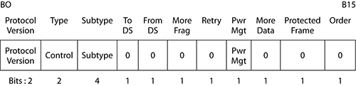
The 802.11 standard defines 15 different data frames, as displayed in Table 6-1. Each data frame is represented by a Type value of 10 and a different group of 4 Subtype bits. These Type and Subtype fields are part of the Frame Control field (Figure 6-1). The 15 different combinations of Subtype fields are displayed in the type description column of Table 6-1. The basic data frame is represented by a Subtype of 0 (bits b7–b4 = 0000). By changing any of these Subtype bits, a modification is made to the basic data frame. Most people are not aware that there is actually a pattern or system to the Subtype bits, with each of the individual bits having a specific meaning. By changing bit 4 (b4) from a 0 to a 1, the data subtype includes +CF-Ack. Changing bit 5 (b5) from a 0 to a 1 will include +CF-Poll. Changing bit 6 (b6) from a 0 to a 1 will indicate that the frame contains no data, specifically, that it contains no Frame Body field. The most significant bit (MSB) of the Subtype field (bit b7) is defined as the quality of service (QoS) subfield, specifying that the frame is a QoS data frame. This pattern or system applies to all subtypes except for 1101, which is Reserved.
Table 6-1: Data frames: valid Type and Subtype combinations
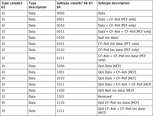
Figure 6-1: Frame Control field
QoS and Non-QoS Data Frames
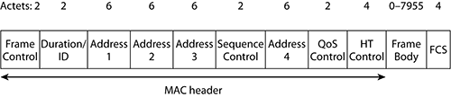
Quality of service stations are capable of transmitting both QoS and non-QoS data frames. It is not uncommon to have a wireless network that consists of both QoS and non-QoS stations. In this type of mixed environment, it is likely that QoS devices will transmit both QoS data frames and non-QoS data frames depending upon the capabilities of the receiving station. When a QoS data frame is transmitted, the QoS subfield (the b7 bit) contains a value of 1, and the frame contains a QoS Control field in the MAC header, as shown in Figure 6-2. When a non-QoS data frame is transmitted, the QoS subfield (the b7 bit) contains a value of 0, and the QoS Control field is not present in the MAC header.
Figure 6-2: Data Frame format
This paragraph will explain when QoS and non-QoS data frames are transmitted in a QoS mixed environment (Table 6-2 provides a summary). When a QoS station transmits to another QoS station, a QoS data frame is used, since both devices are capable of understanding the frame format. Whenever a non-QoS device is involved in the communication, either as the transmitting or as the receiving station, a non-QoS data frame must be used. Broadcast frames are transmitted by default as non-QoS frames, unless the transmitting station knows that all the stations in the basic service set (BSS) are QoS capable, in which case the broadcast frame will be a QoS frame. Like the broadcast frames, multicast frames are transmitted by default as non-QoS frames, unless the transmitting station knows that all the stations in the basic service set that are members of the multicast group are QoS capable, in which case the multicast frame will be a QoS frame.
Table 6-2: QoS and non-QoS transmissions
| Transmitting station | Receiving station | Data frame subtype used |
| Non-QoS station | Non-QoS station | Non-QoS frame |
| Non-QoS station | QoS station | Non-QoS frame |
| QoS station | QoS station | QoS frame |
| QoS station | Non-QoS station | Non-QoS frame |
| All | Broadcast | Non-QoS frame, unless the transmitting station knows that all stations in the BSS are QoS capable, in which case a QoS frame would be used |
| All | Multicast | Non-QoS frame, unless the transmitting station knows that all stations in the BSS that are members of the multicast group are QoS capable, in which case a QoS frame would be used |
Data-Carrying vs. Non-Data-Carrying Frames
As strange as it may sound, some data frames do not actually carry any data. In fact, almost half of the data frames defined do not carry any data. The frames that do carry data are as follows:
- Data (simple data frame)
- Data + CF-Ack
- Data + CF-Poll
- Data + CF-Ack + CF-Poll
- QoS Data
- QoS Data + CF-Ack
- QoS Data + CF-Poll
- QoS Data + CF-Ack + CF-Poll
And the frames that do not carry any data are as follows:
- Null
- CF-Ack
- CF-Poll
- CF-Ack + CF-Poll
- Qos Null
- QoS CF-Poll
- QoS CF-Ack + CF-Poll
So, why have a data frame that does not carry data? Sometimes a station needs to transmit special control information to an access point or another station, without actually transmitting any data. Client stations sometimes use Null data frames to enable or disable power save mode, which is indicated by a bit in the frame control field. Using the Null data frame allows a station to communicate with another device without requiring it to transmit data.
Simple Data Frame
Most 802.11 data frames that are transmitted carry actual data that is passed down from the higher-layer protocols. The data subtype, often referred to as the simple data frame, is the most commonly transmitted data frame. The simple data frame has MSDU upper-layer information encapsulated in the frame body. When the simple data frame is received by an autonomous AP or WLAN controller, the MSDU payload of the simple data frame is transferred into an 802.3 Ethernet frame (this is assuming that Ethernet is the networking platform used by the distribution system).
If you refer to the format of the 802.11 data frame (Figure 6-2), you will see that the 802.11 data frame defines four address fields, named Address 1, Address 2, Address 3, and Address 4. If you are familiar with 802.3, where data frames simply contain a source address and a destination address, having four address fields is likely new territory for you. Even though the 802.11 data frame defines four address fields, in most instances only three of the address fields are used to represent four addresses, and the fourth address is simply omitted from the frame. Do not worry—it is not as bad as it seems.
The first step to understanding the addressing scheme of an 802.11 frame is to identify the logical addresses that are used. The following are the five addresses that are potentially used in a data frame:
Source Address (SA) This is the address where the frame is sent from.
Destination Address (DA) This is the address where the frame is being sent to.
Transmitter Address (TA) This is the address of the station that is transmitting the RF frame.
Receiver Address (RA) This is the address of the station that is receiving the RF frame.
Basic Service Set Identifier (BSSID) This is the basic service set ID of the AP.
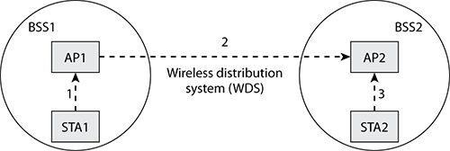
Now we will look at a scenario. In Figure 6-3, there are two stations and two access points. Ultimately, STA1 wants to send data to STA2. STA1 and AP1 form a basic service set known as BSS1. STA2 and AP1 form a BSS known as BSS2. AP1 and AP2 can bridge data between the two BSSs using a wireless distribution system (WDS). For STA1 to send data to STA2, the following three steps occur:
1. STA1 must send the frame to AP1.
2. AP1 must forward that frame to AP2.
3. AP2 must forward that frame to STA2.
Figure 6-3: 802.11 addressing example
At this stage, we will now identify the addressing of each of these transmissions (as you read through the steps, look at Table 6-3 to see the addressing):
1. In the first transmission, STA1 is the source of the data (SA), and STA2 is the destination of the data (DA). STA1 must transmit the data (TA) to its access point, AP1 (RA).
Notice that STA1 is both the SA and the TA, which means that we actually have only three unique addresses, therefore only requiring three address fields.
2. In the second transmission, STA1 is still the source of the data (SA), and STA2 is still the destination (DA). In this transmission, AP1 is transmitting the frame (TA) to AP2, which is receiving the frame (RA).
In this instance, there are four unique addresses, so all four address fields will be used.
3. In the third transmission, STA1 is still the source of the data (SA), and STA2 is still the destination (DA). In this transmission, AP2 is transmitting the frame (TA) to STA2, which is receiving the frame (RA).
Notice again that in this instance, STA2 is both the DA and the RA, which again means that we have only three unique addresses and will require three address fields.
Table 6-3: 802.11 addressing
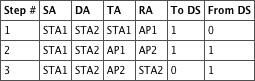
In Table 6-3 there are two columns that have not been discussed yet, the To DS and From DS columns. These are two 1-bit fields that are part of the Frame Control field. These subfields represent whether the frame is going to or from the distribution system. In the first step, the frame is going from the station to the DS, so the bits are 10. In the second step, the frame is going to and from the DS, so the bits are 11. In the last step, the frame is going from the DS to the stations, so the bits are 01. Although not discussed here, in an IBSS (ad hoc) network, since there is no DS, the bits would be 00.
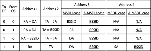
Ideally you now have a better understanding of addressing. Figure 6-4 shows the exact address contents as defined in the 802.11n-2009 amendment to the 802.11-2007 standard. Address 1 is always the RA, and Address 2 is always the TA. The only time the fourth address field is used is when the To DS and From DS bits are both 1. If the frame contains an aggregate MAC service data unit (A-MSDU), then Address 3 and Address 4 (if used) are set to the BSSID address.
Figure 6-4: Address field contents and usage
Addressing and Packet Analyzers
As technology gets more complex, it is difficult to remember all the components in a wireless network. Fortunately, packet analyzers help you so that you do not have to remember everything. When a packet analyzer captures a frame, it processes the frame, converts the addressing information, and displays it not as the address fields but as the logical address. Packet analyzers cannot tell you everything about a frame but can simplify some of the information.
The 802.11-2007 standard allows for the fragmentation of unicast addressed frames. Fragmentation breaks an 802.11 frame into smaller pieces known as fragments, adds header information to each fragment, and transmits each fragment individually. Figure 6-5 shows an MSDU that has been fragmented into four fragments. Although the same amount of actual data is being transmitted, each fragment requires its own header, and the transmission of each fragment is followed by a SIFS and an ACK. In a properly functioning 802.11 network, smaller fragments will actually decrease data throughput because of the MAC sublayer overhead of the additional header, SIFS, and ACK of each fragment. On the other hand, if the network is experiencing a large amount of data corruption, lowering the 802.11 fragmentation setting may improve data throughput.
If an 802.11 frame is corrupted and needs to be retransmitted, the entire frame must be sent again. When the 802.11 frame is broken into multiple fragments, each fragment is smaller and transmits for a shorter period. If interference occurs, instead of an entire large frame becoming corrupted, it is likely that only one of the small fragments will become corrupted, and therefore only this one fragment will need to be retransmitted. Retransmitting the small fragment will take much less time than retransmitting the larger frame. If fragmentation is implemented, retransmission overhead may be reduced.
Figure 6-5: Fragmentation of an MSDU
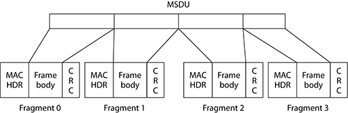
Each fragment is transmitted and acknowledged individually. This provides the ability to transmit a small fragment as opposed to the entire MSDU or MMPDU. Unless they are interrupted because of medium occupancy limitations, the fragments of a single MSDU or MMPDU are transmitted as a sequential burst, allowing the receiving station adequate time after each fragment to transmit the corresponding acknowledgment before transmitting the next fragment.
For the MSDU or MMPDU fragments to be reassembled, the header must contain the following information:
- Frame type
- Address of the sender (obtained from the Address 2 field)
- Destination address
- Sequence Control field: The 12-bit sequence number remains the same for all fragments from the same MSDU or MMPDU, while the 4 bit fragment number within this field is incremented for each individual fragment.
- More Fragments indicator: This is a subfield of the Frame Control field and is set to 0 for the last fragment, indicating that there are no more fragments. For all other fragments, this field is set to 1.
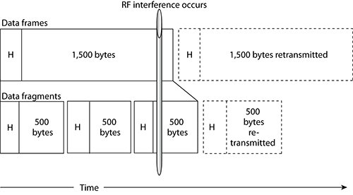
Figure 6-6 illustrates how smaller fragments can reduce retransmission overhead. (Please note that this is a representation and not drawn to scale. Additionally, to simplify the illustration, ACKs were not included.) This illustration shows the transmission and retransmission of a large 1,500-byte frame above and the transmission and the retransmission of smaller 500-byte fragments below. If there was no RF interference, only the solid-lined rectangles would need to be transmitted. Because of the additional headers (H) and the time between the fragments for each SIFS and ACK, the smaller fragments would take longer to transmit. However, if RF interference occurred, it would take less time to retransmit the smaller fragment than it would to retransmit the larger frame.
Figure 6-6: Frame fragmentation
Not all wireless LAN adapters allow you to adjust the fragmentation settings. If you do set your wireless LAN adapter to use a smaller fragment size, you must realize that as you roam between access points and as you move between networks, all of your 802.11 frames will be fragmented using the setting you have configured. This means that if you roam to a location where there is no interference, your station will still be using the smaller frame fragments and will actually perform worse than if you had left the fragmentation value at its largest setting.

Will fragmentation increase throughput? Fragmentation may reduce retransmission overhead in an environment with a lot of data corruption. However, fragmentation always introduces more MAC sublayer overhead to the network. Usually, if fragmentation is used within a BSS, the additional MAC overhead will cause the network throughput to decrease. In some rare cases, the fragmentation threshold settings on an access point may be tweaked to improve throughput by reducing retransmission overhead caused by data corruption. Fragmentation is usually a temporary fix, and the better solution is to find the cause of the data corruption and permanently fix the problem.
With the ratification of the 802.11n amendment, two types of frame aggregation were added to 802.11, aggregate MAC service data unit (A-MSDU) and aggregate MAC protocol data unit (A-MPDU). When a frame of data is transmitted, no matter how big or small the data is, each frame requires a certain amount of overhead to transmit that frame, such as header information, acknowledgments, and interframe spacing. Whether the frame is a big or small frame, the overhead is a necessary part of transmitting that frame. Frame aggregation allows multiple smaller MSDUs or MPDUs to be grouped together into a single frame, reducing the amount of overhead that would have been necessary for each individual frame. As an example, if you needed to rent a truck to move three armoires from one location to another, it would be more efficient to use a single truck that was capable of transporting all three armoires instead of three trucks that are each capable of transporting only one. As shown in Figure 6-7, the difference between the sizes of the trucks is the cargo area needed to hold the armoires. Of course, there is a practical size limit, since it is not likely that we could build or rent a truck that was capable of carrying 100 armoires, and if we did, it would probably be too long to be able to turn around a corner or even a slight bend in the road. Just as using a single truck is more efficient and faster to transport your armoires, using a single frame is more efficient and faster to transmit your wireless data.
Figure 6-7: Efficiency of aggregation

A-MSDU is an aggregation process that combines multiple MSDUs within a single MPDU, as shown in Figure 6-8. The network layer passes the MSDUs down to the MAC layer. Normally at this point each MSDU would be packaged with its own MPDU. With A-MSDU, two or more MSDUs are placed in an MPDU, and a single MAC and PHY layer header is added to the group of MSDUs. If encryption is enabled, then all the MSDUs are encrypted together as a single payload. There are some restrictions for aggregating multiple MSDUs into a single MPDU. The MPDU can only contain MSDUs where the DA and SA values map to the same RA and TA values. All of the MSDUs must also have the same priority value.
Figure 6-8: A-MSDU frame aggregation

A-MPDU is an aggregation process that combines multiple MPDUs within a single PPDU (see Figure 6-9). The network layer passes the MSDUs down to the MAC layer, where an MPDU is created for each MSDU. If encryption is enabled, then each MPDU is encrypted individually. The MPDUs are then passed down to the PLCP sublayer where two or more MPDUs are placed in a single PPDU. The individual MPDUs within an A-MPDU must all have the same receiver address. Also, the individual MPDUs must all be of the same 802.11e QoS access category. A-MPDU also requires the use of block acknowledgments.
Figure 6-9: A-MPDU frame aggregation

One of the key objectives of wireless communications is to transmit information or data accurately and quickly. This is especially true in a multinode environment, such as in an 802.11 network. In this section, we will describe some of the different methods that 802.11 uses to perform rate selection.
Multirate Support
Since 1997, when 802.11 was originally introduced, multiple data rates have been supported. Each new PHY has provided faster speeds along with a larger selection of data rates. Multiple data rates provide 802.11 stations with the ability to communicate at the highest possible speed, dependent upon the current RF conditions. Every wireless adapter has defined minimum received signal and minimum SNR levels. Some vendors release tables or charts that display these values, as shown in Table 6-4, while other vendors release just a few of the values, as shown in the following list of receiver sensitivity values released by a vendor:
300 Mbps: -68 dBm, 54 Mbps: -74 dBm, 6 Mbps: -90 dBm
Table 6-4: WLAN data cell: vendor recommendations

Basic and Supported Rates
As you learned in earlier chapters, the 802.11-2007 standard defines supported rates for various RF technologies. For example, HR-DSSS (clause 18) radios are capable of supporting data rates of 1, 2, 5.5, and 11 Mbps. ERP (clause 19) radios are capable of supporting the HR-DSSS data rates but are also capable of supporting ERP-OFDM rates of 6, 9, 12, 18, 24, 36, 48, and 54 Mbps.
On any autonomous AP or WLAN controller, specific data rates can be configured as required rates. The 802.11-2007 standard defines required rates as basic rates. For a client station to successfully associate with an AP, the station must be capable of communicating by using the configured basic rates that the access point requires.
In addition to the basic rates, the access point defines a set of supported rates. This set of supported rates is advertised by the access point in the beacon frame and is also in some of the other management frames. The supported rates are the group data rates that the access point will use when communicating with a station. After a station associates with an access point, it will use one of the advertised supported rates to communicate with the access point.
Dynamic Rate Selection
As client station radios move away from an access point, they will shift down to lower-bandwidth capabilities by using a process known as dynamic rate switching (DRS). Access points can support multiple data rates depending on the spread spectrum technology used by the AP’s radio card. For example, an HR-DSSS (802.11b) radio supports data rates of 11, 5.5, 2, and 1 Mbps. Data rate transmissions between the access point and the client stations will shift down or up depending on the quality of the signal between the two radio cards, as pictured in Figure 6-10. There is a correlation between signal quality and distance from the AP. As a result, transmissions between two 802.11b radio cards may be at 11 Mbps at 30 feet but at 2 Mbps at 150 feet.
Figure 6-10: Dynamic rate switching

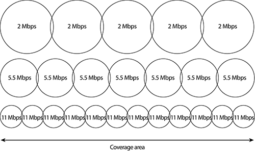
DRS is also referred to as dynamic rate shifting, adaptive rate selection, and automatic rate selection. All these terms refer to a method of speed fallback on a wireless LAN client as signal quality from the access point decreases. The objective of DRS is upshifting and downshifting for rate optimization and improved performance. Effectively, the lower data rates will have larger concentric zones of coverage than the higher data rates, as pictured in Figure 6-11.
The algorithms used for dynamic rate switching are proprietary and are defined by radio card manufacturers. Most vendors base DRS on receive signal strength indicator (RSSI) thresholds, packet error rates, and retransmissions. RSSI metrics are usually based on signal strength and signal quality. In other words, a station might shift up or down between data rates based both on received signal strength in dBm and possibly on a signal-to-noise ratio (SNR) value. Because vendors implement DRS differently, you may have two different vendor client cards at the same location, while one is communicating with the access point at 11 Mbps and the other is communicating at 2 Mbps. For example, one vendor might shift down from data rate 11 Mbps to 5 Mbps at –70 dBm while another vendor might shift between the same two rates at –75 dBm. Keep in mind that DRS works with all 802.11 PHYs. For example, the same shifting of rates will also occur with 802.11n radios shifting between 130, 117, 104, 78, 52, 39, 26, and 13 Mbps data rates. As a result, there is a correlation between signal quality and distance from the AP.
Figure 6-11: Data rate coverage zones
In this chapter, we discussed the different types, actually subtypes, of data frames. Data frames subtypes include QoS and non-QoS data frames, data-carrying and non-data-carrying frames, and simple data frames. We explained when and how the four different address fields are used. Data frame fragmentation and aggregation were explained. We reviewed the support for multiple communication rates and how they are chosen using dynamic rate selection, along with basic and supported rates. PCF and contention-free communications were briefly reviewed.
Know the different data frame subtypes. Identify which frames are data frames vs. control or management frames. You should also be able to identify control and management frames; however, those frame types are covered in other chapters.
Describe fragmentation. Describe fragmentation, why it is used, and how it is used, along with its benefits. Describe how fragment burst is performed.
Understand what data frame subtypes are used for the transmission of QoS and non-QoS data frames. QoS capable and non-QoS capable devices will transmit different types of data frames depending upon the capability of the device they are communicating with. Understand when QoS and non-QoS data frames are used.
Know which data frame subtypes carry data and which do not. There are 15 different data frame subtypes, 8 of which carry data and 7 of which do not. Know the different subtypes and whether they carry data.
Explain the different data frame address fields. Explain the functions of the four address fields. Know the contents of each of the address fields based upon the four different To DS and From DS scenarios. Be able to look at the To DS and From DS fields and identify where the frame is coming from and going to.
Explain the two types of data frame aggregation. Explain what data frame aggregation is. Know the differences between A-MSDU and A-MPDU.
Understand data rates. 802.11 supports many different transmission rates. Know the difference between basic rates and supported rates. Understand why different rates are used, and explain the difference between general and functional policies.
adaptive rate selection
aggregate MAC protocol data unit (A-MPDU)
aggregate MAC service data unit (A-MSDU)
automatic rate selection
basic rates
contention free (CF)
contention-free period (CFP)
DA (Destination Address)
data frame
dynamic rate shifting
dynamic rate switching (DRS)
frame aggregation
From DS
Point Coordination Function (PCF)
point coordinator (PC)
Quality of service (QoS)
RA (Receiver Address)
SA (Source Address)
simple data frame
Subtype
supported rates
TA (Transmitter Address)
To DS
Type
1. In the data subtype field, by changing the bits b7–b4 from a binary 0 to a binary 1, which of the following will be added to the basic data frame? (Choose all that apply.)
A. +CF-Ack
B. (no data)
C. +CF-Poll
D. +ToS
E. QoS
2. When a station transmits a multicast frame, what type of data frame subtype is used?
A. Non-QoS frame always
B. QoS frame always
C. Non-Qos frame unless the transmitting station knows that all stations in the BSS are QoS capable, in which case a QoS frame would be used
D. Two multicast frames are transmitted, one QoS and one non-QoS
E. QoS frame unless the transmitting station knows that all stations in the BSS that are members of the multicast group are QoS capable, in which case a QoS Frame would be used.
3. Which of the following data frames carry data?
A. Data
B. CF-Ack
C. CF-Ack + CF-Poll
D. QoS Null
E. QoS CF-Ack + CF-Poll
4. When transmitting a data frame, the values of the To DS and From DS fields designate the contents of the address fields. During a packet capture of a wireless bridge, what are the values of these fields?
A. To DS = 0, From DS = 0
B. To DS = 0, From DS = 1
C. To DS = 1, From DS = 0
D. To DS = 1, From DS = 1
E. Not enough information to determine the values
5. When looking at a packet capture, which of the following address field statements is false?
A. The receiver address is always Address 1.
B. The transmission address is always Address 2.
C. Address 3 is always the BSSID when the frame is an A-MSDU frame.
D. Address 4 is the source address when both the To DS and From DS fields are 1.
E. The source address is always Address 4.
6. Frame aggregation allows multiple smaller pieces of data to be grouped together into a single frame, reducing the amount of overhead. With the 802.11n amendment, two types of frame aggregation were added. What are the two types? (Choose all that apply.)
A. A-PPDU
B. A-PLCP
C. A-MSDU
D. A-MPDU
E. A-MMDU
7. When A-MSDU is used to aggregate frames, which of the following is true about encryption?
A. All of the MSDUs are encrypted together as a single payload.
B. All of the MPDUs are encrypted together as a single payload.
C. The MSDUs are encrypted individually, prior to aggregation.
D. The MPDUs are encrypted individually, prior to aggregation.
E. A-MSDU does not affect the encryption process.
8. A 2.4 GHz access point is configured with basic rates of 5.5 and 11 Mbps. Which of the following stations could connect to this AP? (Choose all that apply.)
A. 802.11 station
B. 802.11b station
C. 802.11g station
D. 802.11a station
E. 802.11n station
9. When referring strictly to the Point Coordination Function (PCF) media access method, which of the following terms do not apply? (Choose all that apply.)
A. Polling
B. Contention-free period (CFP)
C. Contention free (CF)
D. CSMA/CD
10. A-MSDU is being used for frame aggregation. Which of the following statements is true for this process? (Choose all that apply.)
A. Two or more MSDUs are placed in an MPDU.
B. The MPDU can only contain MSDUs that have DA and SA values that map to the same RA and TA values.
C. If encryption is enabled, the MSDUs are encrypted together as a single payload.
D. A single MAC and PHY layer header is added to the group of MSDUs.
E. The MSDUs can have different priority values.
11. Which of the following statements is false regarding quality of service (QoS) stations?
A. When a QoS data frame is transmitted, the frame contains a QoS Control field in the MAC header.
B. When a non-QoS data frame is transmitted, the QoS Control field in the MAC header is empty.
C. When a QoS data frame is transmitted, the QoS subfield contains a value of 1.
D. QoS stations are capable of transmitting both QoS and non-QoS data frames.
E. It is likely that QoS devices will transmit both QoS and non-QoS data frames in a mixed environment.
12. A wireless 802.11g adapter supports multiple data rates, with the manufacturer specifications showing a minimum received signal of -73 dBm for the 36 Mbps data rate and a minimum signal-to-noise ratio of 18 dB. For the 54 Mbps data rate, which of the following are likely values? (Choose all that apply.)
A. -71 dBm minimum received signal
B. -77 dBm minimum received signal
C. 12 dB minimum signal-to-noise ratio
D. 25 dB minimum signal-to-noise ratio
13. Which of the following are other terms used for dynamic rate selection? (Choose all that apply.)
A. Dynamic rate shifting
B. Fast rate selection
C. Adaptive rate selection
D. Automatic rate selection
14. During the packet capture of a frame from an AP to a station, which of the following statements about the frame header are true if the frame payload originated from a wired-side server? (Choose all that apply.)
A. To DS = 1, From DS = 0
B. Address 1 = RA = DA
C. Address 2 = TA = BSSID
D. Address 3 = SA
E. Address 4 = BSSID
15. Which of the following is true regarding dynamic rate switching? (Choose all that apply.)
A. The algorithms used are proprietary and defined by the radio card manufacturers.
B. The 802.11 standard defines limits for when to switch between different rates.
C. Most vendors base switching upon RSSI thresholds, packet error rates, and retransmissions.
D. Strict adherence to the 802.11 rate selection algorithms provides consistent roaming across devices.
16. A-MSDU is being used for frame aggregation. Which of the following statements is true for this process? (Choose all that apply.)
A. Two or more MPDUs are placed in a single PPDU.
B. An MPDU is created for each MSDU.
C. If encryption is enabled, each MPDU is encrypted individually.
D. The individual MPDUs must all be of the same 802.11e QoS access category.
E. Each A-MPDU will receive an ACK.
17. When A-MSDU is used to aggregate frames, which of the following is true about encryption?
A. All of the MSDUs are encrypted together as a single payload.
B. All of the MPDUs are encrypted together as a single payload.
C. The MSDUs are encrypted individually, prior to aggregation.
D. The MPDUs are encrypted individually, prior to aggregation.
E. A-MSDU does not affect the encryption process.
18. For the MSDU or MMPDU fragments to be reassembled, which of the following must be contained in the header of the fragmented frames? (Choose all that apply.)
A. Frame type
B. Address of the sender
C. Destination address
D. Sequence Control field
E. More Fragments indicator
19. During a packet capture, you notice that there is a series of fragmented frames. These frame fragments can contain what type of frames?
A. Broadcast
B. Multicast
C. Anycast
D. Unicast
E. All of the above
20. When the To DS bit is 1 and the From DS bit is 0, what is the value of the Address 1 field? (Choose all that apply.)
A. Receiver address
B. Transmitter address
C. Destination address
D. Source address
E. BSSID
1. A, B, C, E. The basic data frame is represented by a Subtype of 0 (bits b7–b4 = 0000). By changing any of these Subtype bits, a modification is made to the basic data frame. Most people are not aware that there is actually a pattern or system to the Subtype bits, with each of the individual bits having a specific meaning. By changing bit 4 (b4) from a 0 to a 1, the data subtype includes +CF-Ack. Changing bit 5 (b5) from a 0 to a 1 will include +CF-Poll. Changing bit 6 (b6) from a 0 to a 1 will indicate that the frame contains no data, specifically, that it contains no Frame Body field. The most significant bit (MSB) of the Subtype field (bit b7) is defined as the quality of service (QoS) subfield, specifying that the frame is a QoS data frame. This pattern or system applies to all subtypes except for 1101, which is Reserved. +ToS does not exist.
2. E. If the transmitting station knows that all stations in the BSS that are members of the multicast group are QoS capable, it will send a QoS frame. If the transmitting station were sending a broadcast frame, then it would send a QoS frame if it knew all stations in the BSS are QoS capable. A QoS station would send a unicast frame only to another QoS station. All other transmissions would be non-QoS.
3. A. The only one of these frames that actually carries data is the data frame, also commonly referred to as the simple data frame. The names of all the frames that carry data begin with either Data or QoS Data.
4. D. A wireless bridge connection is also referred to as a wireless distribution system. In this case, both the To DS and From DS bits are set to 1.
5. E. Address 4 is used only when the To DS and From DS bits are 1. Address 1 is always the receiver address, and Address 2 is always the transmission address.
6. C, D. With the ratification of the 802.11n amendment, two types of frame aggregation were added to 802.11: aggregate MAC service data unit (A-MSDU) and aggregate MAC protocol data unit (A-MPDU). Frame aggregation allows multiple smaller MSDUs or MPDUs to be grouped together into a single frame, reducing the amount of overhead that would have been necessary for each individual frame.
7. A. A-MSDU is an aggregation process that combines multiple MSDUs within a single MPDU. The network layer passes the MSDUs down to the MAC layer. Normally at this point each MSDU would be packaged with its own MPDU. With A-MSDU, two or more MSDUs are placed in an MPDU, and a single MAC and PHY layer header is added to the group of MSDUs. If encryption is enabled, then all the MSDUs are encrypted together as a single payload.
8. B, C, E. Since the AP is a 2.4 GHz device, the 802.11a station could not connect. Since 802.11 supports only 1 and 2 Mbps, that station could not connect. The basic rate is required in order to connect to the network. Since 802.11b, 802.11g, and 802.11n are all capable of transmitting at 5.5 and 11 Mbps, they can connect.
9. D. PCF is a central polling method that provides contention-free access. CSMA/CD is a contention method used by wired Ethernet.
10. A, B, C, D. With A-MSDU, two or more MSDUs are placed in an MPDU, and a single MAC and PHY layer header is added to the group of MSDUs. If encryption is enabled, then all the MSDUs are encrypted together as a single payload. There are some restrictions for aggregating multiple MSDUs into a single MPDU. The MPDU can only contain MSDUs that have DA and SA values that map to the same RA and TA values. All of the MSDUs must also have the same priority value.
11. B. Quality of service (QoS) stations are capable of transmitting both QoS and non-QoS data frames. It is not uncommon to have a wireless network that consists of both QoS and non-QoS stations. In this type of mixed environment, it is likely that QoS devices will transmit both QoS data frames and non-QoS data frames depending upon the capabilities of the receiving station. When a QoS data frame is transmitted, the QoS subfield (the b7 bit) contains a value of 1, and the frame contains a QoS Control field in the MAC header. When a non-QoS data frame is transmitted, the QoS subfield (the b7 bit) contains a value of 0, and the QoS Control field is not present in the MAC header.
12. A,D. Since 54 Mbps is a faster data rate than the 36 Mbps, then the minimum received signal needs to be stronger, and the difference between the signal and the noise needs to be greater.
13. A, C, D. DRS is also referred to as dynamic rate shifting, adaptive rate selection, and automatic rate selection. All these terms refer to a method of speed fallback on a wireless LAN client as signal quality from the access point decreases.
14. B, C, D. To begin with, Address 1 is always the receiver address, and Address 2 is always the transmitter address. When the frame is transmitted from an AP to a station, the To DS and From DS bits are 01. In this case, the transmitter address is also the address of the BSSID, so Address 2 is also the BSSID address. Since the source of this frame is the AP, then the receiver address and the destination address are the same in Address 1. Address 3 is thus set to the source address, and Address 4 is not used.
15. A, C. Since the 802.11-2007 standard does not define any specific rate selection algorithm, the algorithms used for dynamic rate switching are proprietary and are defined by radio card manufacturers. Most vendors base DRS on receive signal strength indicator (RSSI) thresholds, packet error rates, and retransmissions. RSSI metrics are usually based on signal strength and signal quality. In other words, a station might shift up or down between data rates based both on received signal strength in dBm and possibly on a signal-to-noise ratio (SNR) value. Because vendors implement DRS differently, you may have two different vendor client cards at the same location, while one is communicating with the access point at 65 Mbps and the other is communicating at 6 Mbps.
16. A, B, C, D. A-MPDU is an aggregation process that combines multiple MPDUs within a single PPDU. The network layer passes the MSDUs down to the MAC layer, where an MPDU is created for each MSDU. If encryption is enabled, then each MPDU is encrypted individually. The MPDUs are then passed down to the PLCP sublayer where two or more MPDUs are placed in a single PPDU. The individual MPDUs within an A-MPDU must all have the same receiver address. Also, the individual MPDUs must all be of the same 802.11e quality-of-service access category. A-MPDU also requires the use of block acknowledgments.
17. A. A-MPDU is an aggregation process that combines multiple MPDUs within a single PPDU. The network layer passes the MSDUs down to the MAC layer, where an MPDU is created for each MSDU. If encryption is enabled, then each MPDU is encrypted individually.
18. A, B, C, D, E. The header must contain all this information. The Sequence Control field is actually made up of two pieces, the sequence number and the fragment number. The sequence number within this field remains the same for all fragments from the same MSDU or MPDU, while the fragment number within this field is incremented for each individual fragment.
19. D. The 802.11-2007 standard allows for the fragmentation of unicast addressed frames.
20. A, E. To begin with, Address 1 is always the receiver address, and Address 2 is always the transmitter address. When the To DS and From DS bits are 10, then the frame is being sent from a station to the distribution system. In this case, the receiver address is also the address of the BSSID, so Address 1 is also the BSSID address. Since the source of this frame is the station, then the transmitter address and the source address are the same in Address 2. Address 3 is thus set to the destination address, and Address 4 is not used.